|
||||||||
|
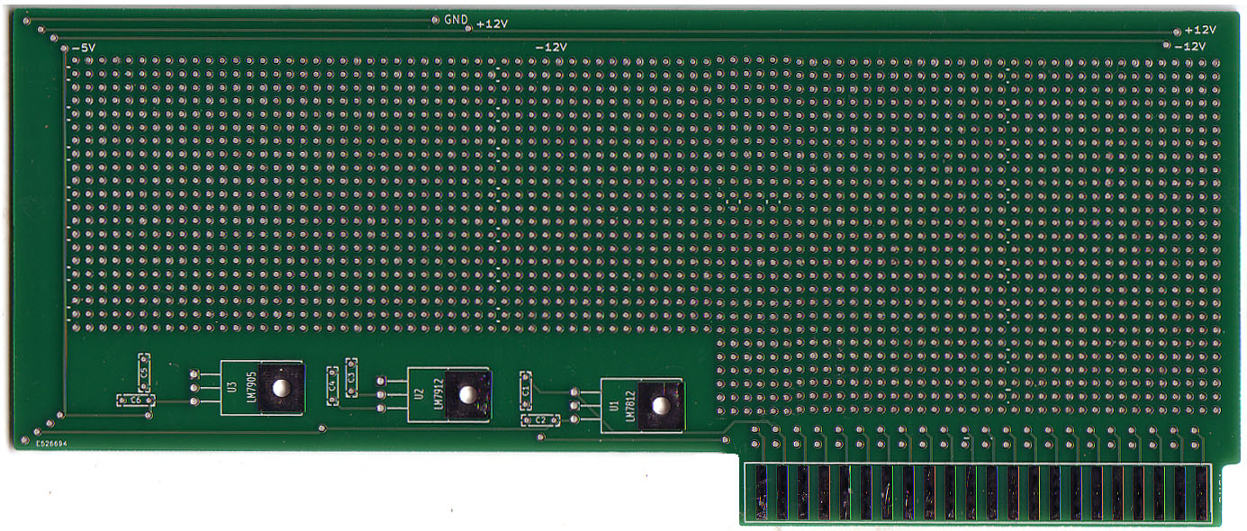
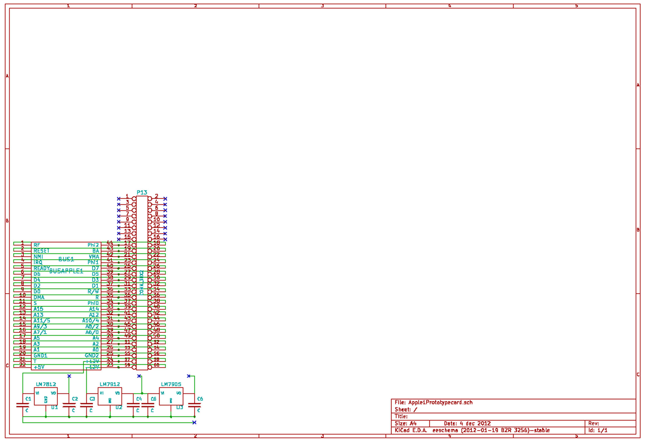
In the second step after i started with
the design of the slotexpansionboard - and after i discovered
that at the slotedgeconnector the + 12 Volt and - 12 Volt only
were present as non stabilized power i revised the availiable
amount of power at this point. By definition of the
transformator delivered with the original Apple-1 there
would only be 1 Ampere availiable. In fact i also had prepared
the slotexpansion-board to be able to get the 12Volt positiv and
negativ also by choice from an external powersupply but there
still was the question open about the use of the expansioncards
in different slots. If the card would be inserted in the "on
board" slot, that slot would still offer only unstabilized
power, because the stabilization would only regulate the power
at the slots of the slotexpansion itself. So i decided to also
offer the opportunity of populating a stabilization on the card
itself - if it was desired to use it within the "on board" slot.
In fact at the slot only the +5
Volt is o´ffered as stabilized voltage and the -5 Volt is
not availiable at all. So i added the opportunity to get
that voltage "droping out" from the -12 Voltage branch. In
case the card should be used in the slots of the
slotexpansioncard there would still be the possibility to
hardwire bridges to the +12 Volt regulation and the -12 Volt
regulation - but still populating the - 5 Volt, if that
powersource would be needed as stabilized voltage. |
||||||||
|
||||||||
|
||||||||
|
||||||||
|
||||||||
|
due to european laws
and german court decision: I hereby declare no responsibility to any "deep links" resulting from the links in this page. I have no influence to the pages linked hereby in this page and the contents in those pages. I therefor can´t take any kind of responsibility to contents in the pages, where these links direct the readers browser to nor to the contents resulting from following up links from those pages. The reference to contents by this links is dependent ro the status of the date when the links have been set ( April 2013 ) and it might occur that references and contents may change by the fact that domains may have been discontinued from their former owners. In such cases i can´t take any kind of responsibility to the changed contents. this is specialy valid to banners, advertisements or merchandising links in the targeted pages.
|