As explained in
the previous pages there are several tasks that can be executed
to keep the DISK II drive in a good working shape.
Some of the tasks are rather simple like cleaning the
drive from dirt and applying some grease to the sliding parts to
ensure smooth
working or adjusting speed of the diskturning within
the correct limitation, some tasks require advanced knowledge
and tools like
adjusting the track zero - and the same is valid to adjusting
the read/writecycle..... this task can only be solved with
advanced electronic
equipment: you will have to use a oscilloscope to be able to
judge the signal at the analogPCB and you should have experience
in using
the scope ....... its also recommended to download the
Circuitplans of the DISK II from SAMs from the site of asimov.
Again i will first give an intro with some basic explenations
for better understanding of the technical details:
We all probably remember that experiment out of the old
schooldays when a copperwire was wound several dozends of time
around
a steelnail and applying some DC-Voltage to the wire .... and
the steelnail became magnetic while the current was applied -
and after
disconnecting the current the steelnail was not magnetic
again.... - well that was a demontration in large to the effect
of electromagnetic
field. The same happens in the read/write head of a
taperecorder and of course also the operation within the
read/write head of a diskdrive
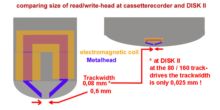
is similar too..... the big difference is the scale of
that..... just for fun a graphic to show that difference:
and as a result of the
different sizes of those electromagnetic coils the electrical
values of voltage differ same scale:
the read/write-head of a cassetterecorder delivers to the
electronic of the PCB some voltage about to maximum of 10
millivolt
( thats 10 thousendth parts of 1 volt or in numbers 0,01 Volt ! )
and the coil of the DISK II passes only 0,5 millivolt to 0,7
millivolt while reading
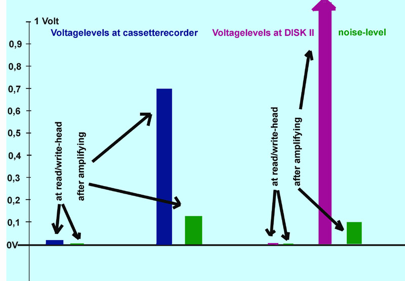
the contents from the disk. In both cases the information must be
amplified up to a value that can be passed to the level the
electronic can use...
Within the cassetterecorder the audioamplifier needs an input of
about 0,7 Volt to amplify the output to the speaker with some 6
Volts.
At the DISK II the required voltage must be amplified up to at
least 4,5 Volt to clean the signal and pass it with 5 Volt to
the controller of the computer !
And one of the important things to know is the fact that the "basic
noise" from tape or disk will deliver some 0,002 to 0,003 Volt
while reading -
compared to the voltage of 0,01 at the taperecorder and to the
0,0006 Volt at the DISK II - and if you amplify the signal of
course the noise is amplified too !
The following picture will visualize this explenation:
 |
In later years the
chipmanufacturers designed special chips for the disk
read/write-heads with integrated special filters to split off
the "noise" at that
very low voltages and to amplify only very selected frequencies to
enhance the ability of reading data from a disk .... that was
the very moment that
drives could be developed with more than 40 tracks ( maximum of 360
kB per disk to 2 sides with 80 tracks and maximum of 640 kB per
disk ) and the
ability to create diskformats with larger compression of data ( the
step upwards from double density to high density with the
advantage of storing
1,44 MB to a disk instead of the former limitation to 640 kB ).
And just beside of this you also should bear in mind that with the given
trackwidth also at the trackalignment a tolerance of 10% to 15%
is permitted
by standard definition. To explain that relation of that to this topic
lets see the next picture:
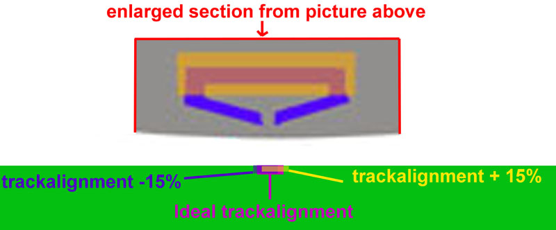 |
This means in
"worst-case-scenario" that if a track is written by a drive
aligned with -15% and thereafter a disk with an alignment of
+15% tries
to read the information the head will only read 70% of
the track and 30% of the empty ( but noisy ) disk besides.....
and this of course will also
have affect to the electrical signal by giving the read
information only 70% of trustable information and 30% of trash !
But now just an
additional fact:
The adjustment of the electronic at the analogboard is
also drifting by another +/- 15% too (!) given
by the tolerance of the used components !!!
All facts together make the difference
between a diskdrive that "reads nearly everything without
mistakes" and a drive that has
at least some 2 % or 3 % of read errors and therefor is forced to
recalibrate more often while reading to finaly get the demanded
information from the disk.
So now after the basics lets get into the hardware and the electronical
task at the analogboard starting first again with a picture
shown in the page before:
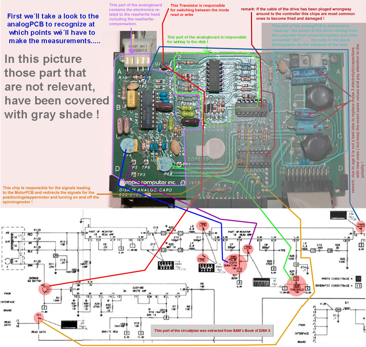 |
Our attention will be fixed to the 2 variable yellow resistors with
the light blue spintops at the bottom of the picture marked as
R33 and R 28 ( in the drawing also
the one indicated with the blue line and the other marked by the
light green line ). Within the circuitplan they are marked by the
enlarged red spots.
For the measurements the testpoints TP2, TP5, TP6 and TP7 will
become important. That will be the related points to view during
the adjustment of the
signals with the 2 resistors the signals at the scope. In the
following part of this page the measurements will be commented
with good examples and bad
ones.
|