Welcome to the CD in CC page of the Colour Classic Compendium
Welcome to
Colour Classic Compendium
Presented by Stuart Bell (stuartsmacs at dsl dot pipex dot com)
|
|
|
|
'CD in CC' - adding a CD ROM drive to a CC
All trademarks, registered trademarks etc. etc. acknowledged. This text and photographs (c) Stuart A Bell 1999 and 2000.
|
It's been done before, of course! At http://homepage2.nifty.com/Kan-chan/zubyo.html there's a beautiful piece of case remodelling by Mr Zubyobyo. It leaves me wondering where the logic board ends up with such a configuration, and the case-work is decidely non-trivial! (For more photographs of the work involved, take a peek at the Japanese version of the above site. It's at: http://member.nifty.ne.jp/zubyo/akky/zubyo.html) Update 20th June 2000: Thanks to Alexey Danilchenko for drawing to my attention the following site, where we see another very neat 'CD in PCC' installation. The same person has also done some neat work to make a PCC and a Power Mystic produce stereo sound - links at the bottom of his page. http://www.eva.hi-ho.ne.jp/tsun/ppccd.html There's also a company in Japan which puts G3 in compact Macs. They put a tray load CD ROM drive in the front of an SE/30, off-centre, and IMHO the best that can be said about it is that the final product is somewhat aesthetically challenged. :- Now, the advent of slot-loading CD ROM drives offers the potential for a very subtle upgrade. It soon became clear that there is no elegant way to keep a 3.5" HD in the modified CC, and a 2.5" SCSI (ex PowerBook) drive is needed. That raises the issue of the different connectors required - see below for the saga! Thanks to Richard Stearn for help, and in particular for his skills with his Dremel tool. |
|
All information is believed correct, but no responsibility whatsoever can be accepted for any consequences arising from your reading of this site. All work is done at owner's risk. Particularly in the region of the CRT and analogue circuitry, potentially lethal voltages may be present, even when the Colour Classic is disconnected from the mains supply. |
'CD in CC' - adding a CD ROM drive to a CC
|
|
1: The Plastic Surgery
Take one CC front panel, and remove every component (CRT etc) from it. Remove from the back of the panel the two push buttons nearest to the floppy slot. It will need carefully cutting away of the 'weld points'. (You may wish to try removing just the nearest single button - this should allow a wide enough slot for a CD, but the surgery required will be a little different. I think that if I did the project again, I'd try that.) |
|
|
Clear the strengthening web in the centre of the back of the front panel, sufficiently to allow the CD drive to get closer to the rear of the floppy slot. Keep part of the web to help support the front panel against the chassis when the computer is reassembled. |
|
|
Extend the floppy slot up to the left hand (curved) end of the push-button hole (under the 'down' arrow of the now disabled brightness control.) Make the internal faces of the slot as smooth as possible - especially the upper face. |
|
|
Clear out any other pretuberances on the back of the front panel which might interfere with the CD drive. |
|
|
You should now end up with a front panel with a wider than usual smile on its face! |
|
|
Take a CC chassis from which almost everything (including all drives, all circuit boards and shielding) have been removed. Using a Dremel, scalpel, fine sander or similar, remove all traces of the tracks on the bed of the upper side of the chassis which previously located the floppy and hard drives. (You need nor remove the outer HD track). The bed must be as smooth as possible, to allow the CD drive to be as low as possible in the chassis. |
|
|
Place the CD drive 'back to front' on the chassis bed, and mark round its edge where it touches the 'cross bar' at the front of the chassis. See the picture to the right, and the two below it. Very little of the cross bar adjacent to the location of the push-button PCB (not to be re-placed) will be left, so great care is needed in cutting out the aperture to accept the CD drive in the front of the chassis. |
|
|
The CD drive located in the CC chassis. We have yet to drill holes to allow it to be fixed in place. |
|
|
Close up of the critical area of the chassis cross bar which has been cut to allow the location of the CD drive. Take that cutting slowly and carefully! NB The drive is inserted from the front of the chassis, so the aperture needs only to be large enough to accept the body of the drive and not the slightly larger front panel. |
|
|
To locate the CD in the CC, first insert the CD drive in the chassis from the front. Holding it in place, then 'dock' the chassis and the front panel. Finally slide the CD drive forward as far as it will go towards the front panel, thus minimising the gap between the front panel of the drive and the slot mooulding in the front panel. The drive should be securely located by drilling two holes in the side of the chassis to line up with mounting holes in the drive and screwing the drive in place. NB Make sure that you use suitably short screws, otherwise damage to the drive is possible. |
|
|
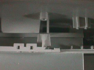
In this photograph, you can see: 1. Top - the rear of the CC front panel, just below the CRT opening. The circular moulding is in the centre of the panel. 2. About one-third up from the bottom of the picture, the cross bar of the chassis. 3. Passing under the crossbar and pushed to touch the rear of the front panel, the CD ROM drive. |
|
|
IT WORKS! Connecting the CD drive, now located in the CC chassis, as an external drive to the target CC/575 shows that the project works physically - ie the drive will load, read and eject CDs OK. While I did download the Pioneer driver, Mac OS 7.5.3 seems to handle the drive OK without the driver.
|
|
|
|
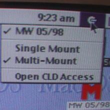
Whether or not the version of Mac OS which you use needs a driver for the slot-load CD, use of the Pioneer one (from their web-site) allows a number of configuration options through the icon-bar icon next to the clock. |
|
A major problem is connecting the 2.5" HD to the SCSI chain. There is no real alternative to using special adaptors, which are very hard indeed to source. Megahaus.com list them, but they consistently failed to reply to my emails - caveat emptor. Craig Ganoe very helpfully pointed me to another supplier of 2.5" - 3.5" SCSI adaptors for data and power: www.cablemakers.com/0scsiadpr.htm They responded to my emails within a few minutes. It costs $16.95. However, to allow package tracking they use a postal service which costs international buyers $40.00 per order. I therefore ordered three, at a total cost of $90. They arrived in less than 72 hours, transatlantic. In fact, coming from CA, transcontinental as well.
|
2: Wiring up the CD in CC Assuming that you have a 2.5" laptop SCSI drive and adapter to use alongside the slot-load CD ROM drive, then I would advise an incremental approach to getting your machine up and running, rather than constructing the whole thing before testing it. My first stage was to get the CC working with the 2.5" HD (and without the CD). This requires no change to the CC's wiring, just the replacement of the 3.5" HD by the (2.5" HD + adapter). First copy the contents of the original HD to the new one. Then switch HDs and reboot. Just let the HD hang out of the back of the CC. Check for SCSI termination issues if it won't boot with the new HD.
|
|
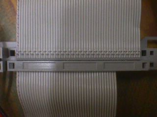
The next stage is to get the CD and new HD working together, not necessarily with them located in the CC chassis. You need a power splitter to provide power to the two drives. You'll need a new cable from the logic board edge connector to provide the SCSI connection to CD and HD. First remove the covering clip from the SCSI cable on the edge connector - see photo. |
|
|
Then carefully remove the cable. Don't pull hard - the metal connectors will come with it, I assure you! :-( Put a new cable in its place - about 15" long, with 50-way SCSI connectors at the far end and about 6" in from the far end. Apply firm even pressure, using a 'workmate' or a vice with wooden packing to protect the plasrtic. NB Check the required length for yourself. Re-install the logic board edge connector, noting the routing for the cable to the analogue board (right). |
|
|
The floppy and front panel push-button board connectors are redundant (but see section 3 below), and can be neatly stored in the front part of the CC chassis (right). Now connect the SCSI and power connectors to the HD and CD. This will require some care in threading and folding. Take your time. Try alternative routings. At the moment, the new HD has not been fixed. Slide it down alongside the CD drive. When you are happy with the wiring and HD position, fix the HD by using a suitable screw through one of the many ventilation holes in the side of the chassis into one of the fixing holes in the HD. Again, make sure that the screw is not too long. |
|
|
I then tested the machine before putting the case back on. I am not recommending that you do so. You could kill yourself. OK? |
|
|
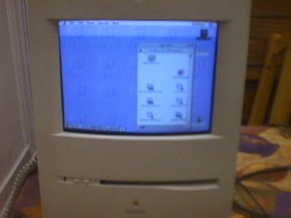
When the CC boots up, you should see an icon for your HD and, assuming that there is a CD in the CD drive, one for the CD also. |
|
|
Project accomplished!Because I was already using a logic board from a Performa 575 (32MHz 68LC040) upgraded ito a full 68040, running with 36Mb RAM, I installed MacOS 8 off the CD, which worked a treat! No more floppy installs. No more floppy anything, or course, so make sure that you can network your 'CD in CC' to another Mac which has a floppy if you might ever need to use one.
|
|
|
|
|
|
3: Reinstating the front panel LED Initial experiences of accidentally leaving the 'CD in CC" machine turned on, as a consequence of there being no indicative front panel LED due to the absence of the push-button PCB which also holds the LED, confirmed the need for the issue to be addressed promptly. |
|
In fact, it's an easy problem to solve, assuming that you have not removed the ribbon cable and connector for the push-button PCB. Simply cut the PCB into three sections; a left-end with just the LED and resistor; a middle section; and a right-end with the edge connector. Discard the centre section, and connect the two tracks for the LED with suitable wire. On the edge connector, the two tracks are the front and back 'right-most' tracks. On the left-end, be careful not to apply too much heat to the surface mount resistor, otherwise it may be damaged, or 'swim away' on a layer of solder! Then, with the CC case removed, taking all due precautions and at your own risk, you may wish to plug the right-end PCB into the ribbon connector, to check operation.
|
|
|
CC trivia: The reference to SLICE on the PCB is to the in-house Apple code-name for the CC project. |
|
|
Then separate the chassis from the front panel and install the left-end of the PCB using the original mounting screw (which you have, of course, kept safely!) It requires a Torx-8 driver, ideally. |
|
|
Finally, re-build the 'CD in CC', and all should be well. If you wish, you could change the LED colour at the same time. On the Colour Classic Power Up web page, there's a link to instructions for putting a blue LED in. |
|
|
Finally There's no place for the standard speaker with the CD in place of the floppy. (Normally the speaker is located behind the floppy drive.) However, a round 3" speaker can be located in the front of the chassis facing downwards - the location which was, I believe, the original intention of the CC design team.
|
PS If the order of the work I performed seems confusing, please remember that I first did the plastic surgery on a spare CC front panel and chassis, and then moved the 'contents' of a donor CC across to the modified panel and chassis, adding the new wiring elements in the process. It would be perfectly possible to make a 'CD in CC' without spare components, in which case you may wish to do the wiring first, with both CD and new HD 'hanging off the back' of your CC, before doing the plastic surgery and installing the CD and HD. |


<-back to the Power Colo(u)r Classic page