Cinema Display: repairing the DVI connector
I posted a question in the forums about repair of a cinema display 20-inch, whose DVI connector was broken off. I finally have the solution and a working Cinema display again and as promised in the thread I would post the info regarding what color is what pin. So here it is.
I used a DVI connector from the VGA to DVI adapter from Apple, I stripped it to the bare essentials so only the black connector is left. Make sure you don't destroy the pins or else all is lost.
I needed to remove the Analog RGB part of the DVI connector, cause it is not fitted in the Mini DVI to DVI adapter of Apple.
Anyway its not needed except if you want to use it with a VGA card. But think that not the purpose of a Cinema display 
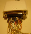
Following are some pictures of the Color coding of the cinema display cable, connected already too the DVI connector.
This is also the orientation of the chart below, so take note of that. Otherwise the display doesn't work at all.
Also note that the ground cables are not yet connected to the pins, this is just the test phase, so now its working I'm going to strip the wires again and solder them to the pins in a NEAT way
Here you can see the connector in the Mini DVI to DVI, connected too my MacBook.

Other view of the connector

And an another with more light.
From left to right the upper pins are:
Black, B.White, B.GND Blue, Yellow, Orange
Middle pins:
Brown, Br.White, Br.GND Red Brown
Lower pins:
Pink, Pnk, White, Pnk.GND, GND, Pnk/Br.White Pinkish/Brown
Some more info, the TMDS pairs are the 4 big pairs of 3 wires packed in the foil. Each pack consists of 3 wires:
1 colored
1 white
1 bare wire
The 4 packs are colored with a Pink pair, a brown pair, a black pair and a strange pinkish/brownish pair.
So in the chart below ( And up) the B.White for example means the white wire of the black package. Same with B.GND.
The other 5 pins are separated and without foil, and consist of yellow, brown, red, blue and orange.
So the only way you can go wrong is with the brown TMDS pack and the pinkish/brownish TMDS pack. Also note the both are lighter from color then the Brown that is a separate wire, so you can't go wrong there.
So here is the chart I made with the color coding. Again please note the orientation of the DVI connector. The chart depicts the orientation like on the above pictures.
Back view of Cinema display connector

[pre]
1 TMDS Data 2- Digital Red- (link 1) Pink
2 TMDS Data 2+ Digital Red+ (link 1) White of pink
3 TMDS Data 2/4 Shield GND of Pink
4 Not used on 20 inch
5 Not used on 20 inch
6 DDC Clock GND of pinkish/brown
7 DDC Data White of Pinkish brown
8 Analog Vertical sync Pinkish/brown
9 TMDS Data 1- Digital green- (link 1) Brown
10 TMDS Data 1+ Digital green- (link 1) White of Brown
11 TMDS Data 1/3 Shield GND of Brown
12 Not used on 20 inch
13 Not used on 20 inch
14 +5V Power for display Red
15 GND GND for pin 14/8 Brown
16 Hot-Plug Not used
17 TMDS Data 0- Digital Blue- (link 1) and digital sync Black
18 TMDS Data 0- Digital Blue+(link 1and digital sync White of black
19 TMDS Data 0/5 shield GND of Black
20 Not used
21 Not used
22 TMDS Clock-shield Blue
23 TMDS Clock+ Digital clock+ (links 1 and 2) Yellow
24 TMDS Clock- Digital clock- (links 1 and 2) Orange
[/pre]
| Attachment | Size |
|---|---|
| 3.35 KB |
Comments
great work...
and lot's of bravos and thank-a-lots for the infos!
destroyed DVI connector in 30" cinema display
Hello!
As you have mastered the smaller one maybe you have the info as well about the 30" Apple Cinema Display?? I have similar situation - I have the 30 inch display with torn DVI connector and torn power connector - as far as I know the Mac to which it has been connected fell of the table (but the screen stayed ON the table). The difference is that 30" uses Dual Link so there are pins connected in the center of the connector as well.
I am looking as well for the easy way to identify the connections in the power cable as the wires had been torn directly from the plug (I have the plug but I will have to cut it partially in half probably to solder it back) so it is not easy to see which color of the cable is which voltage - maybe you know something about that?
I am located in Krakow, Poland, far away, and the screen had been sent from Canada. If you may have some info for me please contact me at a64@interia.pl
Lukasz
re: 30" Apple Cinema Display
I understand wanting to hack, crack, and fiddle, but isn't an otherwise-good 30" display worth just buying a replacement cable from Apple? (even if it has to be shipped to Poland!)
Still, if the pinout/wire-color-scheme is findable, I suppose it's worth posting here.
dan k
30" Cinema display DVI connector
Hello,
Yes, I will try this "buy new cable" option as well but I think it is going to take ages and cost a lot. I am quite good with soldering, and of course it is a challenge! so far I have tested that the power connector is NOT broken (Fire Wire is, but I do not need the hub on the monitor at all) so I am looking as well for an easy way to get the new cable.
I have managed to localize some of the wires (as they are broken with some wire left at the connector side but to be sure I need the full color scheme.
Luk, a64@interia.pl
destroyed DVI connector in 30" cinema display
The problem is that 30" uses Dual Link so there are all pins connected, and there is even more wires than connectors so some ground wires must be connected to the same pins. I have the original connector so I have been able to localize some colors but there is a way to many white and ground wires to be 100% sure
So far I have localized that the cable is build from 7 groups of 3 wires coded by the main color + white + ground
in the following groups:
light orange, white, black ground
pink, white, black ground
light pink, white, black ground
light yellow, white, black ground
light blue, white, black ground
light green, white, black ground
white, black, black ground
and individual wires:
blue, red, yellow, orange, brown
So there are 26 wires and the connector has only 24+1 pins, and 2 pins looks like never soldered.
ANYBODY HAS THE COLOR CODING AT THE DVI CONNCECTOR PLEASE?
If you may have some info for me please contact me at a64@interia.pl
DVI pinout
I suppose anyone who is messing with a DVI display might find a nice pinout chart useful. While this chart doesn't give the wire colors, it may be useful as a logical organizer to help figure out the function of any particular wire.
dan k
Thank YOU Dan K
Hello,
It looks like I am almost there - just to solder it - which will not be that easy. Your link, top of the page, leftovers of the cable and logic gave me the following: (connector seen from the soldering, analog (unused) part on the right, pins from left to right three wire groups in paranthesis -I will do the drawing, I do not have time now):
(black, white, ((ground)), light yellow, white), BLUE, YELLOW, unused
(light brown, white ((ground)), light blue, white) RED, BROWN, ORANGE
(pink, white ((ground)), light blue, white) (ground, white, light orange)
apple macbook pro DVI pinout
Hey,
nice work. I am looking for the macbook pro dvi pin layout to solder my own DVI to Svideo cable. I think it is just a cable, or do they include a RGB to Svideo converter in the cable? 20 bucks is rather expensive, but on the other hand apple always was a bit pricey...
well, does anybody know?
Wont work anyway
Hi! Ive got a Apple Cinema Display with a broken connector. I have tried to do it like the schematics above. But it wont work? Is there any other way to see if the screen is OK?
I have the same problem
Hello!
I have 2 cinema display 23"
Both have problems with dvi connector.
We tried your solution but is not working.
Maybe I do something wrong.
Can you help me ???
We realy need this 2 pieces in our studio.
Thank you!
Re: Cinema Display: repairing the DVI connector
Hello everybody,
This is a working fix for the cinema display dvi connector.
I repaird my monitors cable yesterday, it took about 1 hour, since I´m not a very good soldier:)
Anyway very happy I have found these instructions, they are working, I have the 23" cinema display.
Thumbs up for Iguana!!!
Re: Cinema Display: repairing the DVI connector
This is exactly the fix that I think I need. Do you Iguana or anyone still have the images that you posted with this? I don't see them here. Thanks!