Building a Case for the Replica I
By Larry Nelson
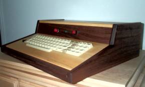
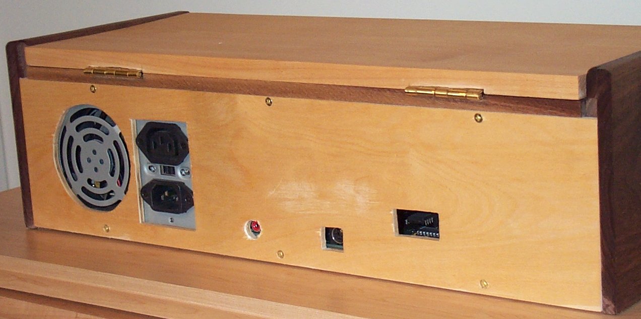
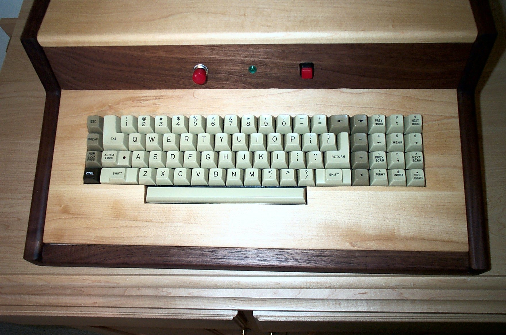
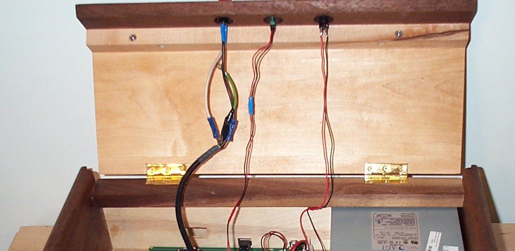
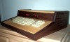
As a person with multiple hobbies, I finally found a way to combine at least two of my part-time interests: namely, woodworking and the Replica-1 computer by Vince Briel. After buying the Replica, and adding the serial board, I made a box to put my Apple-1 Replica into. A few months later, Vince came through for the whole group of Replica enthusiasts with authentic ASCII keyboards. My old Replica case wouldn’t take the keyboard I bought from Vince, though, and I decided to build a case that would comfortably hold the new (old) keyboaof my system.
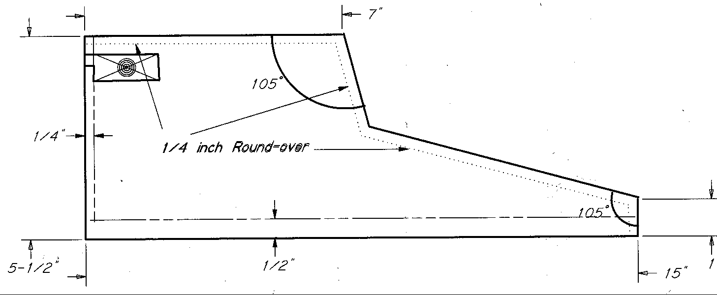
Start out with a base of MDF (medium-density-fiberboard) cut to 18 1â?„4 inches by 14-3/8 inches. If 1â?„2 inch plywood is available, that could be used just as well. (The MDF was cheaper at the Home Depot.)
Then make two sides from 15 X 5 1�2 X 3�4-inch pieces of walnut. These boards I cut on a band saw to the shape shown in the drawing. Lacking a band saw, one could cut the boards to shape with a handsaw, a scroll saw or a jigsaw. Carefully sand the rough-sawn edges smooth. Route a bull-nose on the two sides, using a 1�4-inch round-over bit. See the pictures for the placement of the round-overs. Don’t route the inside of the sides on the 1inch vertical front edge or the inside of the back edge. If you lack a router and round-over bit, use a wood rasp to round over the edges.
Now add a 1/2-inch rabbet to the bottom edge of each side piece. The rabbet is 3/8-inch wide (half the thickness of the side) and 1â?„2-inch deep for the base to fit into. Rabbet the back edge of the sides 3/8-inch by 1â?„4-inch to inset the back into the sides.
Remember, the two sides are mirror images of each other. Be careful to correctly orient the two sides before rabbeting the edges, or you’ll wind up with two right or two left pieces. Don’t ask me why I bring this up, but my scrap-box seems to have a spare side in it.
The front edge is a piece of walnut wood 19 1â?„4 X 1 1â?„4 X 3â?„4. Shape it as shown in the drawing. Use a rasp to round over the outer edge of the front edge piece. The 15 o bevel on this piece will not properly shape with a round-over bit in a router. Notch the front edge piece on both ends as shown in the drawing.
At the top of the back, add a piece of wood 18 1â?„2 X 2 X 3â?„4 to hold the hinges for the top. A 1â?„4-inch by 3/8-inch rabbet on the back side of this piece allows the back to fit flush.
The back of the case is a piece of 1â?„4-inch birch plywood, cut to size to fit into the rabbets. Before fastening the back in place, test fit the power supply and Replica circuit board in place. Mark the back to cut out access for the power cord, the PS fan, the monitor connection and the serial plug. Since placement of these holes may vary, I am not providing dimensions. After carefully marking the necessary holes in the back, drill and cut as necessary.
There are three more pieces of wood needed to complete the case. Since I have a planer, I planed the wood for these three pieces to 1â?„2 inch thickness. If allowance for the difference in thickness is made, the top and front cross piece could be 3â?„4 inch thick. The key board however should not be thicker than 1â?„2-inch since the keys of the ASCII keyboard do not extend through 3â?„4-inch boards far enough. An alternate key board could be 1â?„2 thick plywood.
The top is 17 1â?„2 inches by 7 inches. The key board is 17 1â?„2 by 7 1/2 inches. These two pieces are maple in the original and are made by edge-gluing oversize boards together until you have sufficient width, then cutting the pieces to the correct width and length on the table saw.
The vertical cross piece between the top and the keyboard is also 17 1â?„2 inches long. I started with a width for this board of 3 inches, but trimmed it to 2 1â?„4-inches after experimenting with the fit. The angles involved make calculations hard to do. Into this board you will mount the power (on-off) switch, the RESET switch, and an LED for power indication.
You will have to drill three holes centered in the board for these switches and light. First mark the location of the three holes, drill 3â?„4 inch holes to within 3/16-inch of the front face, then switch to the finish bit size to complete the holes. This will allow the locknuts to be recessed into the vertical cross piece.
Drill a 1/4 inch hole, 1/2 inch deep in the center of each end of the top back piece. Drill matching 1/4 holes, 3/8 inch deep in the sides. We will use two pieces of 1/4 dowel, 7/8 inch long, to hold the top back piece in place.
Dry assemble the base, the two sides, the front edge and the top back piece to check for proper fit. Then glue the five pieces, clamping the assembly and checking for square in vertical and horizontal directions. Set the assembly aside.
Round the top of the front edge of the top piece using your 1â?„4 inch round-over bit or wood rasp.
Cut two triangle pieces of 1â?„2inch scrap wood or plywood into triangles with a 15 o angle. Glue and clamp them onto the inside of the two sides of the assembly. These triangles go to the front of the cabinet and support the key board. The key board is not fastened to the case itself but just rests on the triangles.
I found that the best way to cut the key board inlet was to make a cardboard template, test-fitting it over the ASCII keyboard until satisfied with the fit. Center the cardboard template on your case key board, draw the outline, and carefully cut out the pattern with a scroll saw or jigsaw. Smooth the cut edges with a rasp and sandpaper, test-fitting the key board onto the ASCII keyboard until it fits with enough clearance to allow all the keys to move freely. When satisfied with the fit, set the key board aside. Don’t attach the ASCII keyboard until after you have applied your finish.
The vertical cross board attaches to the top piece with 4 - #6 X 1-inch screws, glue and the support piece cut as shown in the drawing. If you have cut it to the proper width, the vertical cross board will contact the key board with its bottom edge and hold the key board in place.
Now add hinges to the underside of the top piece to attach it to the top back piece. I inset the hinges, using a chisel to cut the inlets, but this is not necessary.
With all the pieces finally done, you are ready for sanding and finishing. Sand away all scratches and rough edges with 80 grit sandpaper. Then progress through 120, 180, 240, 320 and 400 grit sandpaper until the surfaces are as smooth as possible. Clean off all dust and fingerprints with mineral spirits. Allow the surface to thoroughly dry, and then rub on two or more coats of Danish Oil or other finishing oil. Allow the oil finish to dry for 24 hours.
Assemble the ASCII keyboard by screwing it onto the back of the finished key board.
Mount the switches, LED, power supply and circuit board as previously explained. Connect all the wiring. This is not a wiring manual. If you have questions about wiring the Replica, refer to the instruction manual. Contact Vince Briel if necessary.
Add four feet to the bottom of the case. I used stick-on felt pads available at the local hardware store.
Fasten the back to the case with small screws. Plug it in. Load Microchess. Have Fun.
Materials:
- Back: 18 1â?„4 X 4 1â?„2 -- 1â?„4-inch Birch Plywood
- Base: 14 3/8 X 18 1â?„4 -- 1â?„2-inch MDF or 1â?„2-inch plywood
- Front: 18 1â?„4 X 1 -- 3â?„4-inch Walnut
- Sides: (2) 15 X 5 1â?„2 -- 3â?„4-inch Walnut
- Key Board: 17 1â?„2 X 7 1â?„2 -- 1â?„2-inch Maple
- Top: 17 1�2 X 7 – 1�2-inch Maple
- Vertical Cross: 17 1�2 X 3 – 1�2-inch Walnut
- Back Top: 17 1�2 X 2 – 3�4-inch Walnut
- Triangles: (2) 6 1�2 X 2 – 1�2-inch MDF or 1�2-inch plywood
- Hinges: 1pr. 2-inch X 1 3/16-inch, Brass
Miscellaneous Materials:
- 1â?„2-inch X 4 wood screws (6)
- 1-inch X 6 wood screws (4)
- Wood Glue
- Sandpaper in 80, 120, 180, 240, 320 and 400 grits
- Danish Oil Finish
- Felt feet for case (Set of 4)

