Expanding the Memory to 20k
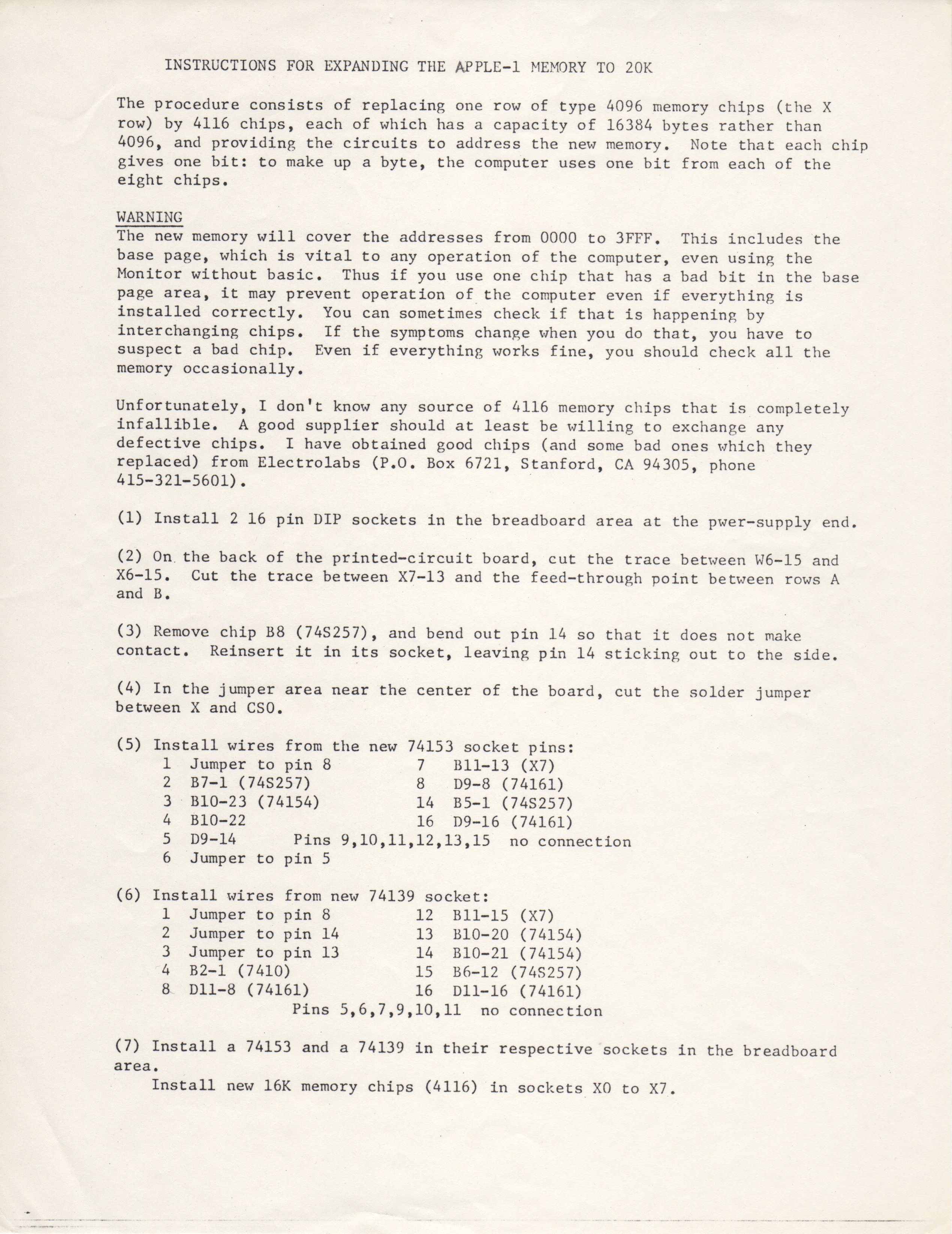
INSTRUCTIONS FOR EXPANDING THE APPLE-1 MEMORY TO 20K
The procedure consists of replacing one row of type 4096 memory chips (the X
row) by 4116 chips, each of which has a capacity of 16384 bytes rather than
4096, and providing the circuits to address the new memory. Note that each chip
gives one bit: to make up a byte, the computer uses one bit from each of the
eight chips.
WARNING
The new memory will cover the addresses from 0000 to 3FFF. This includes the
base page, which is vital to any operation of the computer, even using the
Monitor without basic. Thus if you use one chip that has a bad bit in the base
page area, it may prevent operation of the computer even if everything is
installed correctly. You can sometimes check if that is happening by
interchanging chips. If the symptoms change when you do that, you have to
suspect a bad chip. Even if everything works fine, you should check all the
memory occasionally.
Unfortunately, I don't know any source of 4116 memory chips that is completely
infallible. A good supplier should at least be willing to exchange any
defective chips. I have obtained good chips (and some bad ones which they
replaced) from Electrolabs (P.O. Box 6721, Standord, CA 94305, phone 415-321-5601).
(1) Install 2 16 pin DIP sockets in the breadboard area at the pwer-supply end.
(2) On the back of the printed-circuit board, cut the trace between W6-15 and
X6-15. Cut the trace between X7-13 and the feed-through point between rows A
and B.
(3) Remove chip B8 (74S257), and bend out pin 14 so that it does not make
contact. Reinsert it in its socket, leaving pin 14 sticking out to the side.
(4) In the jumper area near the center of the board, cut the solder jumper
between X and CS0.
(5) Install wires from the new 74153 socket pins:
1 Jumper to pin 8 7 Bll-13 (X7)
2 37-1 (74S257) 8 D9-8 (74161)
3 B10-23 (74154) 14 B5-1 (74S257)
4 B10-22 16 D9-16 (74161)
5 D9-14 Pins 9,10,11,12,13,15 no connection
6 Jumper to pin 5
(6) Install wires from new 74139 socket:
1 Jumper to pin 8 12 Bll-15 (X7)
2 Jumper to pin 14 13 B10-20 (74154)
3 Jumper to pin 13 14 B10-21 (74154)
4 H2-1 (7410) 15 B6-12 (74S257)
8 D11-8 (74161) 16 Dll-16 (74161)
Pins 5,6,7,9,10,11 no connection
(7) Install a 74153 and a 74139 in their respective sockets in the breadboard
area.
Install new 16k memory chips (4116) in sockets X0 to X7.
- Printer-friendly version
- Log in or register to post comments