Some time ago I found an old Brose ASCII keyboard from Germany (post some more about this later), which I want to use with my Apple-1 build. I thought it was smart to test it in isolation before hooking it up to an Apple-1 or ][. As a software guy I am quite new to electronics. So I came up with a design of an ASCII Keyboard Tester / breakout board. Maybe it has been done before, but I thought it was a good excercise for me anyway.
I tested the 8 ASCII leds setup on a breadboard and it works great. During the design I added connectors for the Apple-1 and Apple ][ keyboard and test leds for Clear and Reset. For these two leds I am not sure if I wired them correctly, maybe they should be the other way around?
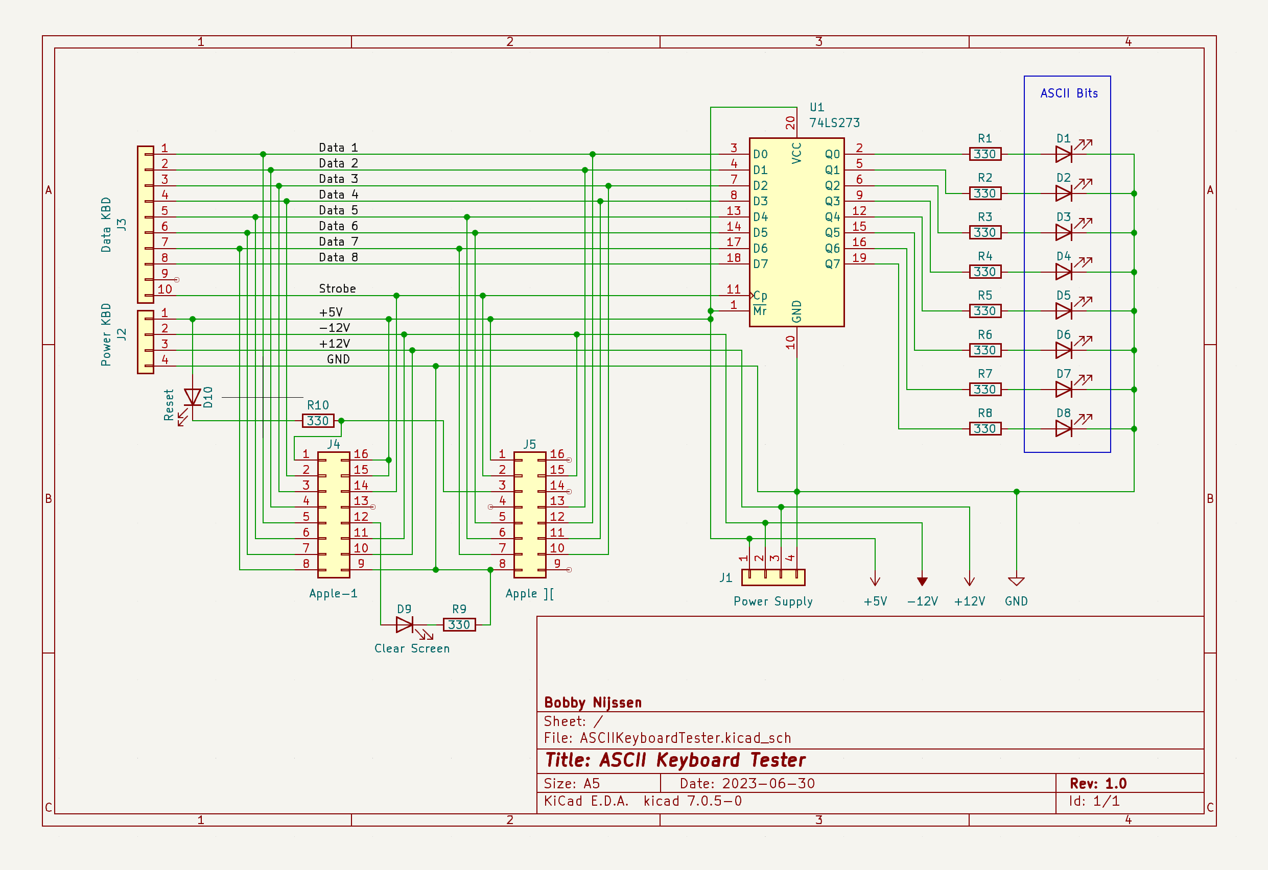
Here are the schematics, looking forward hearing what you guys think of it. I think I will make a pcb of it as well.
Regards from Holland!
Interesting, useful and neat design!
Very clever use of the latch as not all keyboards keep the data bits out when no key is pressed.
I would add a 555 as a monostable connected to the STROBE in order to capture and stretch the signal in time to make it visible with an LED.
This would also help in diagnosing possible problems with the STROBE line. Without it, the latch would never be activated and would make it appear that no data bit is active, when in fact the STROBE itself is the problem.
I'm not so sure about the LED + 330 Ohm resistor on the RESET line: it could 'hide' imperfect internal contacts inside the RESET button... the LED might go off, but then RESET might be ineffective (it happened to me once...)
I would pass both the RESET and the CLRSCR through TTL gates: if they detect the keypresses correctly so will the computer.
Great work! :-)
Claudio - P-LAB
Thanks for the feedback Claudio, I made some modifications, it is getting complicated, but I am not sure this will work.
I added a bistable latch, I hooked that one up to the stobe and clear/reset signals. The enable is always on, so you see the NO STROBE led first. After one keypress with strobe it switches to STROBE and the ASCII bits are shown. Same for the clear and reset, pushed once and they stay on (test succeed), I could add a reset button somehow.
Is this the right fix? I have my doubts on the reset led hooked up to the complementary output.
Think this will suffice without a 555? I will try it on the breadboard.
Schermafbeelding 2023-06-30 om 20.52.40.png
I personally wouldn't mess around with flip-flops unless strictly necessary.
Consider that CLRSCR and RESET might get 'stuck' after being pressed and in this case the flip-flop test would still pass.
My thinking is that an ASCII/TTL keyboard is a combinational device, inputs must be matched by precise outputs: I would keep things as simple as possible.
Beyond the dedicated CLRSCR/RESET keys and the STROBE line, a Data Bits decoding stage would definitely add value.
Thinking about it, an Arduino-type microcontroller board could integrate all the circuitry you have set up, and have a serial output (or even on an external display) of what is typed/pressed.
Assuming you use the STROBE as an interrupt, I'm confident that the microcontroller will be quick enough to read the 8 data bits in sequence before they disappear (if the keyboard under test don'e leave them set), but you need to do some testing and read some documentation...
I already did some timing analysis on that, if you think you might need it I can try to look it up, at the moment I don't remember the figures...
Enjoy your design and good tests!
Regards,
Claudio - P-LAB
Hi Claudio,
Thanks a lot for the input. I revised the design a bit and have a working prototype now.
I used a 74LS00 for the Reset / Clear lines, a 74LS123 to visualize the high a low edges of the Strobe and a 74LS374 as a latch for the bits. This last one is buffered so you can hook up more stuff if you like, for example two 7 segment hex displays.
I understand your idea of using a microcontroller, but I like the thing using components out of the ASCII keyboard era.
I am designing the pcb in KiCad now. It is a lot of fun actually, will post some more details soon.
Regards,
Bobby
Had a lot of fun with KiCad in designing the pcb. The board is about 9 x 9 cm and still has some room for experiments, like adding two 7 segment displays. I will order some pcbs and test it further.
As I am new to this, any settings I have to check in KiCad before generating the gerbers and sending them off to PCBWay or the like? I have already run the design rules checker and fixed some positioning errors.
Regards from Holland,
Bobby
Schermafbeelding 2023-07-23 om 20.54.46.png
Schermafbeelding 2023-07-23 om 20.44.54.png
Looks pretty handy!
I like it, but you forgot to add the 2-digit hex display. ;-D
That would be an awesome addition.
Pretty good for a beginner!
This is a great idea and I love your initiative (and the Netherlands...I have a sister there).
Very well done, congratulations!Let us know if it works well!
C.
Yes you are right, but I discovered that the ICs needed to drive those are pretty rare in a compact size. Or I have to look better... They fit on the breadboard area anyway (see picture). First I will experiment with this some more. Maybe I will make a 7-segment edition as well later on.
Thanks!
Schermafbeelding 2023-07-23 om 20.30.52.png
Yes, the integrated BCD to 7 segment decoders that also decode hexadecimal A..F (I think it was the IC 9368) are now quite expensive. ..
The more common 7447 unfortunately handle only decimal digits.
A (very cool) alternative are the TIL311 / DIS1417 integrated decoder+display, I believe there are also reengineered modern equivalents.
Regards,
C.
DM9368N ICs are $1.77 on eBay. Shipping is slightly more but if you buy a quantity of them, shipping becomes inconsequential.
Also, you can save some board space if you use an in-line resistor pack for R1 thru R8. An example of such HERE but you'll need to move the resistors to the other side of the LEDs (ike you did with R9) so you can tie one side of the resistor pack common.
I thought about the HEX displays some more, I will create an adapter PCB that fits into the socket of U1 (the 74LS374). So you can add two HEX displays if you want to and keep the 'base' board simple and cheap. All the signals that you need for the displays go through that socket. Using the DM9368's for this would be a good idea.
Anyway I ordered some PCBs and will test some more when they arrive.
First, I love this! Nice work.
Are you planning on making kits or completed units available? Or is somebody planning a PCB run with intent to resell? I would be interested if the price is reasonable.
Hi! Thank you for your enthousiasm. Actually, I am waiting for the pcb's to arrive. Then I want to test them first. I only want to sell stuff that works! I was also thinking of creating a kit. So plans to sell PCB only, unassembled kit and I am not sure yet about assembled kits.
The HEX display I will design next when I have the PCBs tested. So kind of an add-on.
Please send me a PM if you want to discuss more details.
Some progress, received the first batch of PCBs.
Discovered a little defect, I forgot the ground connection of U2. In the KiCAD schematic the line was not connected fully, so no trace was there on the PCB, argh. Also used 3mm led footprints, I meant to use 5mm. I also have a couple of more improvements in mind, so I am up for a second revision already. For the rest it is working great.
The design of the Hex Display Adapter is working as well. I will finish the design and I will add some pictures.
The second production, some improvements of the ASCII Keyboard Tester:
- the U2 IC should be grounded now
- changed the layout a bit for the 5mm LEDs, also the breadboard area is larger, the overall board size is the same
- added a pull down resistor for the 8th byte, as this byte is not used by a lot of ASCII keyboards, you could use it to test the parity bit as well
- changed the power connector horizontally to be able to connect the Hex Display
- added a hole to in the middle to support the optional Hex Display
I designed the Hex Display using two DM9368, with proper 0-9 and a-f display:
- it can be used stand alone (using the separate connectors) or on top of the ASCII Keyboard Tester using the J1 connector (this connector is rendered wrong by KiCad)
- for the latter the 74LS374 can be pulled off the Keyboard Tester and put in the Hex Display board
- it has a jumper to active or deactivate the 8th bit (ASCII or full byte mode)
I ordered a few PCBs again, fingers crossed, hopefully I made no mistakes this time!
Regards from Holland,
Bobby
Renders.png
Hi,
Very nice and useful. I have some old keyboards in doubtful state, but never the time or mood to check them. With your board, I have no excuse to check all my keyboards. Great work.
Thank you
Adding to nijssen's creativity and making a few slight modifications, I thought I'd build a single board solution using the original board he made ...
A few mods however...
1. Changed the Keyboard sockets to "split contact" sockets for easier insertion
2. Added a couple decoupling caps to the circuit
3. Put the 7-segment digits directly on the board. (took a bit of wiring & time but it was fun to do)
ASCII Keyboard Tester Front.jpg
ASCII Keyboard Tester Back.jpg
That looks great macnoyd. I actually designed the breadboard area to be big anough to do just this. Nice setup! About those extra caps, you added those for the 7 segment drivers only? And I do not know of those split contact sockets, going to look into those. And of what type are those white header connectors? They look a bit more rigid.
Thanks for sharing,
Bobby
I had quite a lot of questions of people using the ASCII Keyboard Tester. I had some time to put together a manual, here it is. And yes macnoyd, you are mentioned in it ;-). If I missed something please let me know.
https://www.applefritter.com/files/2024/01/10/ASCIIKeyboardTester-Manual-v1.0.pdf
Thanks for putting the manual together and for the reference! Much appreciated.
Redarding your questions above, I added 2 decoupling capacitors across the 7 segment driver ICs because there were no other decoupling caps in the circuit.
You likely shouln't need decoupling for this particular project due to limited and slow switching transitions and the fact you're only switching LED's, but I put them in there anyway out of good practice. Also, the IC sockets used for the keyboard headers are the same type used for inserting ribbon cable headers (that use a split contacts) rather than a machined pin. I would have used the white ones that Apple used in the ][+ and ][e but I can't find them anymore.
Regarding the white 0.1" spaced connectors, I pulled them out of my misc. parts drawer from other projects and I used them because I thought they looked better. (and are gold plated) ;-)