So you want to build a Power Colour Classic?
<-back to the introductory page
|
|
 |
|
With acknowledgment to 'Takky' who documents the wiring and principles of the Power Color Classic on his web site, and to my good friend Richard Stearn, electronics engineer and Unix guru, who did all the nasty bits of the project for me - like the wiring of the analogue board connector - and then helped track down the problem of the auto-powering-down CC/.5400 when we seemed to have a failed project on our hands. All information is believed correct, but no responsibility whatsoever can be accepted for any consequences arising from your reading of this page. All work is done at owner's risk. Particularly in the region of the CRT and analogue circuitry, potentially lethal voltages may be present, even when the Colour Classic is disconnected from the mains supply. All trademarks, registered trademarks etc. etc. acknowledged.Method and wiring (c) The Club for Creating the Strongest Color Classic. This text and photographs (c) Stuart A Bell 1999 , 2000 and 2001. |
|
|
While those in the USA think of a 'Color Classic', those in the true English speaking world(!) know better!
Incidentally, perhaps someone could tell me what lettering appears on the front of machines sold in mainland Europe and other countries whose first language is not English. |
 |
|
|
|
 |
|
| 1. First change the screen resolution to 640 x 480. | |
One common problem is that, even after much tweaking of the controls, the final screen has wide black borders at either side. The bekkoame site offers one solution, which is to increase certain voltages on the analogue board. An alternative is to add a capacitor (1 to 4nF) rated at 1500V+ at position CL26, adjacent to the flyback transformer. This worked well for me. Thanks to Joerg Garritzmann who first proposed this idea.Here's a little more detail about the modification:The ideal is to do the standard conversion, then adjust the display to get the widest display before it becomes impossible to get nice straight sides (barrel distortion sets in!). Then add 1nF/1000pF, and adjust again to optimise. If it's not wide enough, add a bit more capacitance and repeat. Joerg found no improvment beyond about 3nF; I found that 4nF was optimal. Because the effect of the mod. is to 'spread out' the TV signal over a longer period for each line, maximum brightness is reduced, but not by a large amount. This method doesn't put extra strain on components by increasing key voltages, which the alternative method on the "640 x 480" site does. So, ideally, you need to source several caps in that range. Incidentally, this fine tuning, including removing the analogue board each time, takes far longer than the actual modification to get 640 x 480 in the first place. But it's well worth it. You need every inch of display available at that resolution. And just to clarify WHERE position CL 26 is, here's a photo showing a 4nF capacitor in place next to the flyback transformer: |
Most software these days needs 640 x 480 resolution. My normal advice would always be to do the VGA screen upgrade, as outlined below. However, when performing a 'Mystic' upgrade, recently, I came across one analogue board that could not be persuaded to produce a decent VGA display, as excessive pincushion distortion was impossible to erradicate. I therefore performed the 'logic board modification', and ended up with a very clean 512 x 384 (or 560 x 384) display. I've yet to analyse fully the issues around using such a display with a PowerCC.
If, when you've followed those instructions, you find that you have large black borders either side of the screen, a modification devised by Joerg Garritzmann should help - see the panel to the left. |
 |
"High-Res" and VGA modifications In summer 2001, it became clear that there are two different 640 x 480 modifications possible for Colour Classics. What we used to call the 'VGA' mod in fact makes the CC compatible with the Apple 13" display (640 x 480 at 67Hz) and should be called the 'High-Res" modification. Full details are given at http://www.bekkoame.ne.jp/~t-imai/cce1.html. Eric Neuman has done a brilliant "re-translation" of this site at: http://www.geocities.com/edakoda The true VGA conversion produces a 640 x 480 screen with a 60Hz refresh rate. This modification puts less strain on the components of the CC's analogue board, and is strongly recommended. Chris Lawson has detailed the VGA modification at his site. |
| 2. Preliminaries |
|
| First, see the excellent site at http://member.nifty.ne.jp/frogeye/takky.html for a full description of what is involved. Print out the pages. Wait a week. Re-read the pages which you've printed out, again and again! If you still want to go ahead, read on. This site is assumes that you have the 'Takky' instructions to hand. He's the clever person who devised the whole idea; I simply followed his instructions, and this site only amplifies and perhaps clarifies them a little. |
To be accurate, Takky is synthesized from two names, i.e. Tak and Akky. Tak is the author of Mystic Room. (http://www.bekkoame.ne.jp/~t-imai/). Akky is the president of CCSCC. (http://member.nifty.ne.jp/akky/). They developed the basic technique for Takky tune together. Other CCSCC members also participated in the development of Takky in many ways. The translator into English of the 'Takky' site was Yoshihisa Sugimoto, to whom I am indebted for the clarification of the name 'Takky'. For simplicity, the rest of this page will continue to refer to 'him' rather than 'them'. |
|
|
First, source your logic board. As 'Takky' explains, you can use any board from the 630 to the 6500 family of machines. They can be divided into four groups: |
| '630 boards: | 6200/6300 (excluding the 6360) boards: | 5400/6400 (and 6360) boards: | 5500/6500 boards: |
| The LC630 and Performa 630 have a 68LC040 processor running at 33Mhz; The Quadra 630 has the 68040 processor, with an FPU. Both should give a 4x to 5x performance improvement over the CC. They are available for around $20 on eBay, and you should get a complete machine, with a '630 connector' (see below) for little more. | These are PPC powered Mac boards. However, their design is severely compromised (see the 'Road Apple' section in Low End Macs. Even though a poor design, they will still give a good performance increase to a CC. They also give MacOS 8.5+ compatibility, and usually do not need extra PSUs - unlike some later boards. | These eradicate many of the design problems of the 6200 etc. range. However, as Takky explains, you need a 3.3v supply adding to the CC. 1MB VRAM is more than enough for the CC's 640 x 480 display. Speeds up to 200Mhz were made, and you can even add a G3 upgrade. I've had problems, although other people have had success with x400 boards. |
My 6500 board runs beautifully in my Power CC. They offer even higher speeds than the x400 range - up to 300Mhz. Their 2Mb VRAM cannot really be exploited on a 10" screen. As G3 upgrades to 500MHz (10x system bus speed) have now been announced, I await the first 500MHz G3-powered Colour Classic! But beware that a G3/L2 card will require further major 'surgery' to your PCC. |
|
Which board is best depends entirely on what board you can locate at what price. 'List' prices for all the boards make the upgrades quite non-cost-effective. You need to source a used or refurbished board at a sensible price. Having spent two years getting my Power Colour Classic fully functional, I have experience of five different boards: A kind person sold me a used 5400/120 logic board. This was the first board I used in my PCC. It worked perfectly, except that about 2 seconds after power-up it would issue a 'power-down' signal to the analogue board, and the whole system would shut down. Disconnecting the 'power-off' signal between the logic and analogue board connectors stopped that happening, but the logic board 'thought' that it had closed down, and it had to be re-started by using the on-board reset button. In turn this meant that the machine could not be restarted by a non-technical user, nor a child. Richard and I spent many many hours trying to isolate the problem. We thought that it might be a PSU issue, or one relating to the monitor sense line encoding. Later, I tried a 6400 board in the same PowerCC. It, too, powered down soon after boot. I then got a fully working PCC running with a 6200 (75MHz) board. It was perceptibly slower than the 5400 board (and much slower than when I temporarily used the 6500 board in the PCC!) But it didn't 'auto-power-down' like the 5400 did, and it was still much much faster than a standard CC. So, I was left with the situation that x200 boards and x500 boards were fine, but x400 boards were not. Why? We then found out that x500 boards produce a 3.3v supply on-board for their own needs, whereas x400 boards do not. Hence the 5500 boards, despite having a PCI artchitecture which use a 3.3v supply work fine. The conclusion would appear to be that although the 3.3v line seemed to be fine, my x400 boards didn't "like" it, perhaps because it dipped during the boot process. Whatever the reason, with the plummeting prices for x500 boards - typically around $80 on eBay in summer 2001, there seems little reason to me, given the effort involved in the whole Power Colour Classic process, to go for anything less than a 5500 or 6500 board. My 5500/250 board works fine in my PCC - at last! Having also completed a 'Mystic' upgrade (putting the logic board from an LC575 in a CC) and then upgraded it to a full 68040 processor with 36Mb RAM, I've come to the conclusion that such a CC/575 is as 'snappy' as a low-end PowerCC. I believe, therefore, that the effort required to produce a PCC if you intend to use anything less than a 100MHz PowerPC logic board is probably not worth it, other than in the satisfaction of doing it, and the fact that such a machine, unlike a CC/575, can run 'PowerPC-only' software. |
| Second, source your '630 connector'. | Third, prepare your operating system. |
| Takky recommends cannibalising a complete '630 computer - a cost effective approach in 2001 at about $20. Alternatively, you can salvage one from a 6200, 6300, 6400, 6500 or 5x00 equivalents. All should be fine, but newer and more powerful machines reduced to the status of 'spare parts donor' are likely to be rare, expensive, or both. |
You need to consider the version of Mac OS installed on your CC's HD. Ideally, you don't want to have to install a new OS at the same time as changing logic boards, if only to help track down any problems which may occur. In the long term you may well want to install Mac OS 8.x, but the 68030 processor in the CC won't run Mac OS 8. Conversely, some PPC logic boards won't run some earlier versions of System 7. There is a list of 'what boards run what OS' on the Apple Technical Information Library (TIL) site. In my case, I ascertained that the 5400 board would run System 7.5.5. The CC will also run that system. A further complication is that copies of 7.5.5 may have been installed for PowerMacs, for 68k Macs, or for both. We need the last of these. So, even if you have 7.5.5 already installed, unless you are absolutely certain that it was installed for all Macs, I'd advise a clean installation of a fresh 7.5.5, for all Macs and all parts of the OS - just to be safe. The Color Classic can run this quite happily, so the OS installation can be done well in advance of any logic board upgrade. Mac OS 7.5.3 can be downloaded free of charge from the Apple site, and then the upgrade to 7.5.5 can be downloaded and applied. Note, however, that you won't be able to do this once you've upgraded to certain PPC logic boards, since the 7.5 and 7.5.3 installers will refuse to try to install with those boards which need 7.5.5! Once the upgrade is completed, you would probably be well advised to upgrade your new PPC/CC to Mac OS 8.1 or higher. There are many reported problems with 7.5.5, and also with 7.6. Opinions as to which is best are divided, but 8.1 solves many of the well known 5400/6400 Mac OS problems. Later, I installed Mac OS 8.5. The facility which its Finder offers to display directories with user-controlled column widths and compressed text is very useful on 640 x 480 screens like the CC's. |
3. The Upgrade |
|
| Takky explains how it's done, and I will not repeat what he says here. What follows are my comments and clarifications to be read alongside Takky. He did all the work - mine is simply derivative. | |
| a. First, dissemble the CC. After removing the back (careful - high voltages) you need to separate slightly the chassis which holds all the 'works' from the CRT and front panel. Remove the logic board by sliding it out. To remove the chassis, free four very stiff clips at each corner, and 'wiggle' the 'cage' free from the front panel. Be careful that you do not strain any of the several connections between the CRT and the analogue board. If any look as if they are under strain, far better carefully to disconnect them. You can now remove the metal shielding which surrounds the cage and gain access to the area 'behind' the CC's main logic board connector. It is not essential to remove the chassis from the front panel any more than this at the moment, and having removed the shielding you may rejoin the chassis and front panel again. | 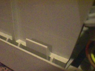 |
| Photo shows one of the four clips (with the metal shield already removed). | |
| b. Relocate the connector. Since 630 family logic boards are 4cm longer than the CC's, the new connector will have to be mounted that distance further back than the original one. The new connector can be fitted into slots which you must cut in the plastic chassis, 4cm away from the normal location. On the outside of each side of the chassis, apply a sticky label. This will aid marking out, and reduce the danger of your power drill bit slipping. |  |
| Underside of Colour Classic with shielding removed, showing original (higher) and approximate new (lower) positions of logic board connectors. | |
| The longer 'slot' is the extension of the circuit board runners. The normal logic board connector is shown in place on the right of the photo. The new position is 4cm to the 'left' in the photo. Not all the longer slot needs to be cut away; only that to the left of the indentation in the chassis, where it becomes too narrow to accept the board without the cut being made. On one side of the chassis, the slot which will hold the connector is extended to the edge of the chassis, to allow insertion of the connector. Obviously, remove the logic board and the connector before doing any cutting. The cutting can best be achieved by those with limited equipment by using a power drill (preferably variable speed) to drill a series of adjacent holes, possibly using a series of drill bits of increasing size, then connecting the holes up using a hand file. |  |
 |
|
| This is the view when the slots have been cut, prior to tidying up the slots with a hand file. You can then remove the sticky label! | |
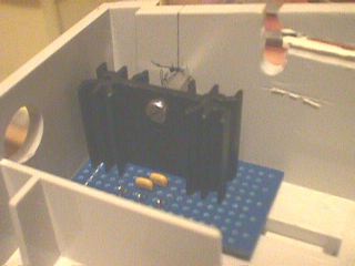
| A major area of chassis clearance is the 'box' which obstructs where the SIMMs will need clearance above the logic board almost up to the connector (shown in the 'new' position). This requires ruthless butchery with drill and file. But be careful, since the floppy drive is on the other side of that plastic bulkhead! |  |
 |
|
| This is the view with one end of the connector located in the newly cut slots. | |
| Now the rest of the chassis must be cleared of obstructions. Remember that the new logic board carries a battery and probably SIMMs, and so space must be created for all these things as far back as the new connector. However, note that on some boards the SIMMs are located further away from the edge of the logic board than is the case with the CC's board, so the area to be trimmed will vary. |  |
| Once all the chassis area has been cleared, the underside of your CC should look something like this. The connector shown is the original CC one at this point, in the 'new' position. The connectors to the HD and floppy have been disconnected at the drives, as on my machine they were really too short once the connector had been moved. I replaced them with longer cables. | |
| Note the extra small slot cut in the chassis to extend the new mounting point for the connector. To mount it, first insert the connector into the slot on the other side of the chassis, then, gently pulling the sides of the chassis apart, slide the lug up the narrow slot shown above and into its position. |  |
| Note that at this stage we have not fully cleared the circuit board slots so as to allow insertion of the CC logic board to the full extent of the new connector position. This will be done just before the main wiring is done, so that in the mean time we can relocate the connector back where it came from, and use the CC! | |
| c. Wiring up the main logic board connector | |
| If you have purchased the 630 connector with the harness as a service part or have removed it from a donor machine with the wiring still in place, then you will need to remove the cables that will not be required or will be significantly changed when used inside a CC. Remove all but the connector to the floppy disc (i.e. the 20 way connector). Don't forget to cut the relevant single line in the FD cable. | If you want to use an IDE hard drive, then the IDE cable may be long enough - I did not investigate this possibility as I was going to use the 1GB SCSI drive which I had previously installed inside my CC. If you have no intention of using an IDE drive, then there is no need to connect a cable to the connector. Nor need you have any internal SCSI devices when using an IDE HD. However, some people advise that when using an early 'IDE/SCSI' Mac without any internal SCSI devices, system stability is improved by putting a SCSI terminator on the external SCSI socket. |
SCSI connectionTo connect the SCSI drive to the logic board connector, you will need a longer piece of 50-way cable than is supplied either with the 630 connector or with the CC. I bought a 60 cm (2 foot) length to be safe, but only a little over half of that is needed. Bear in mind that the cable comes out of the 'wrong' side of the 630 connector, and so allow for the extra length required. You may reuse the 50 way connector that connects to the CC's HD, or else source a new one - easily obtained from any decent electronics component shop. |
For connecting cables to all these IDC connectors, you need to apply firm even pressure along their whole length. Use either a vice with softwood packing to reduce the chances of damaging the connectors, or else a 'workmate' type piece of DIY equipment which has a long vice assembly. After making the connections to the main connector, having left the cables over-long, I stripped the 'far' end of every wire to test for continuity and shorts at the 630 connector end. This should be unnecessary if you connect the cables properly in the first place, but I like to reduce the chances of silly problems! For the cable between the 630 connector and analogue board connector, I purchased a length of 40 way multicolored IDC connector (although 30 way would suffice) and then used the same colour-coding which Takky uses to form the link. Thus, you can visually check the connections against a colour printout of the relevant page on the Takky site. |
IDE Problems?Alexey Danilchenko (dalex at iname dot com) had great problems in connecting an IDE drive to his Power Colour Classic. After much research, he has provided the material for a definitive page about the 'IDE Question". |
|
| d. Power Supply Requirements |
As noted below, installing a PCI logic board may well require the addition of a 3.3v supply. The situation is less clear with the standard 5v and 12v supplies. Certainly, the CC supply is marginal. Some people have, apparently, had no problems. Some who have done a (LC575 + 601 accelerator) - "PowerMystic" conversion have added an extra supply in front of the logic board connector, but with the moved connector required for the larger logic board, there is not enough room. Takky's advice is that if your converted machine will not boot and/or the power supply LED flickers or is dim, then you will most likely need to add an extra PSU, probably in the space behind the disc drives where the speaker normally resides. This extra PSU can be wired up to the mains connector (ideally controlled by a relay, so that it turns off when the main supply turns off), and can be used to supply the HD and possibly the cooling fan. I found that a PSU from an external CD-ROM drive would just fit in the space available, but in the end did not need to use it. If you are installing a 630, 5200, 6200, 6300 or 5300 (not 6360) logic board, then you can skip the next step, which is only required for cards with PCI slots. |
| e. Installing a 3.3v regulator for PCI logic boards. | |
| In theory all such boards (6400, 6500, 5400, 5500 and 6360) require a 3.3v power supply as well as the usual 5v and 12v ones. Takky explains all this. Read what he says. Read the notes on his Q&A page as well! However, the latest view is that 5500 and 6500 boards will run without a 3.3v line (although their PCI slots probably won't.) | The obvious place to put the voltage regulator and accompanying components is to the very front of the CC, between the front panel and the newly located logic board connector, where the power supply cables will pass in any case. (See the Takky wiring diagram which shows how the cables pass from one end of the connector to the other.) |
 |
 |
| Close up of front of CC and new connector; you've got about 30mm of space in which to locate the 3.3v regulator on a small board. | General view of base of Colour Classic, with logic board connector in its new location. If required, the 3.3v regulation circuit will be located between the connector and the front panel of the CC. |
|
Construct the voltage regulator circuit on a suitable small piece of board, with a heatsink. It may be possible to bolt it to the side of the chassis using a pillar and bolt. As Takky notes, 3.3v regulators can be hard to find; we used a Micrel MIC29150 device. Since creating my PCC, I've noticed that RS Components (www.rswww.com) now accept orders from individuals, and that they list numerous suitable regulators on their web site. They don't apparently stock the Micrel device, but a search under 'keyword' for "3.3v regulator" gives hundreds of hits, and several of the first 20 listed are for the required regulators. They even supply data sheets in .pdf format. Buying should be straightforward for UK customers - those outside the UK will need to check with the RS web site. |
 |
| Above: the 3.3v voltage regulator circuit, bolted in the corner of the chassis, in front of where the logic board connector will be located. | |
| f. Clearing out the track for the new logic board | If you have followed the previous instructions closely, you will have made the fixing locations for the lugs which hold the '630 connector' and also cleared away much of the plastic which would otherwise stop the new logic board from taking up its correct location. You now need to extend the tracks on which the CC logic board runs so that it can slide into the new connector in the new position. Use a small sharp cutter and files as required to achieve this. |
| g. Connecting up the new connector and the analogue board connector. |
Unless you have a spare analogue board connector, this is almost the point of no turning back. (Not quite, since you could always remake the connections to the original logic board connector, but what follows means that quite a bit of work would be needed to reinstate the old logic board in your CC.) To gain access to the analogue board connector, you will need to separate completely the chassis from the front panel and CRT. Disconnect the CRT from the analogue board, noting carefully where the connections are made. so you can reinstate them later, taking all due precautions for high voltages. Then prise open the four clips which hold the chassis to the front panel, and lift the chassis clear. Then remove the analogue board from the chassis. Now might be as good a time as any to make the alteration which Takky describes to the analogue board, so as to get the correct voltage on the S1 connector. When routing the new link under the analogue board, watch out for sharp solder spikes which could pierce the insulation. |
|
It's been pointed out that the description of the new link to be made as part of the analogue board modification is minimal to say the least. ;-) The two photographs to the right should make things clearer - the actual wire link is some way from the connector to the logic board, and at the opposite end from S1. Note that some different analogue boards were used during the life of the CC, so 'your mileage may vary' - or rather your analogue board may be different. |
|
 |
 |
| Close up of analogue board connector, with original wiring as fitted in CC. | General view of chassis of CC, when removed from front panel, and analogue board and HD removed. |
| To access the analogue board connector, you will need to remove the push-button PCB first. Then remove the analogue connector, and carefully remove the cable which connects to it. | Then make the connections between the multicolored cable from the '630 connector' to the analogue board connector which Takky details. Note that the cable will need to be much longer than the straight-line distance between the two connectors, due to the need for twists and turns around the SCSI cable. See the (poor) photo of the wiring loom! This is by far the most problematic part of the whole upgrade. Make each connection carefully. When completed, use a meter to check that every connection has been made properly, before installing the wiring loom. |
| h. Completing the wiring loom. | |
 |
|
| Analogue connector wired up using multicolored IDC cable, to match colour scheme in Takky's diagram. | |
 |
 |
| Completed wiring loom for upgraded CC. On left is the SCSI cable - to the right the power connections (with 3.3v regulator board), push-button cable, FD cable and analogue cable. | |
| Then make the connections to the push-button connector which Takky details. | Then make and carefully check the power supply connections which Takky details. We used a screw terminal block to connect the supply to the HD to the main wiring harness - it can be seen in the final underside view of the modified CC, below. PCI logic board users will need to wire in the 3.3v supply. |
| Now install the main logic board connector and the new wiring loom. The push button PCB can now be reaffixed over the analogue cable. | |
 |
 |
| Push button PCB reinstalled with new analogue connector wiring behind. | Underside of upgraded machine, with wiring loom largely located between the new logic board position and the front of the chassis. |
| i. Reassemble the computer, and power up! | |
| Reinstall the analogue board on the chassis. Then reunite the chassis and the front panel. Note that two protrusions from the panel dock into holes in the chassis; ensure that they do not damage the wiring loom which may be just behind one of the holes. | |
|
STOP PRESS: Rumours are flying of the iClassic - a G3-powered compact Mac for the 21st century. Click on the pic for more information. |
Then re-connect the CRT assembly and the analogue board. Finally, press any reset button which may be on the main logic board, install the logic board in the chassis, put the back cover on the CC, power up, and you should have a Power Colour Classic! |
 |
 |
|
|
|
| If you get problems, Takky has a useful debugging section. Also, see his Q&A page. If our experience is anything to go by, the most likely cause of problems is bad connections in the logic-board to analogue board cable. You really cannot be too thorough in checking it out before installation. | Also, remove the possibility of OS-induced problems by making sure that you have installed a version of MacOS which both the original and the new logic boards will be able to use. Having a 6500 Mac in addition to the CC, I was able to check out the 5400 logic board with my installation of Mac OS 7.5.5 on a Syquest drive, before copying the OS installation across to the CC's HD. |
| Finally, I would add that this is a superb piece of work by Takky and the members of the Club for Creating the Strongest Color Classic in Japan. When it works, it works brilliantly. I am very happy with my Power Colour Classic. But before you start, do recognise that there is a possibility, dependent on your level of Mac knowledge and electronic expertise, that you will end up with a dead computer that will never show a 'happy Mac' again. |
|
|
4. Later additions |
|
|
The first addition with my 5400 board (after taking the RAM up to 32Mb) was a 256K L2 cache card. If your logic board allows such a thing, then a £15 / $25 expenditure will give a 25% or so performance improvement. Larger L2 caches improve things further, but you'll want a G3 upgrade in that L2 slot eventually, won't you? ;-) [Just to claify - a G3 card will NOT fit without further chassis modification - it's just too tall.] The second addition was an Ethernet card. Comm Slot II Ethernet cards are rare and expensive. Also, many will not fit without further plastic surgery to the CC. Check out http://homepage.mac.com/wtnb/commii.htm for the details. PCI cards are common and cheap - just make sure that Mac OS drivers are available. (Earlier pre-PCI logic boards will need Nubus Ethernet cards - available second hand -or else a Comm Slot I card for 6200 series machines.) The 1-slot PCI riser card that comes with 5400 and 5500 computers will just fit in a Power Colour Classic, holding the Ethernet card parallel to the main logic board, as the photo to the right shows. The 2 slot risers from 6400s and 6500s will be too tall. Ideally, a back panel will eventually provide support for the card! Comm Slot I cards for 6200 series machines will just fit inside a CC chassis, if you remove the metal bracket around the Ethernet socket. |
 |
Latest News:Union-Tribune Publishing mentioned this page in a feature on CCs and PowerCCs in October 2000. Power Colour Classic featured in the New York Times, August 2000! The article was written by Paul Kunkel, author of the brilliant book Apple Design. Sadly, the article gets a few facts wrong, misquotes me, and then fails to give the URL of this site, even though some of the 'quotations' are lifted straight from it. Grr! Wired.com discussed the Colour Classic upgrade craze in May 2000, mentioning this site. |
 |
|
This site was featured in the February 2000 issue of MacMania, a Brazilian Mac magazine. The cover is shown above. www.macmania.com.brThe publisher tells me that the text of the article, written in Brazilian Portuguese, reads something like this: The Power Classic Love for the Macintosh challenges frontiers. Some people do anything for their older machines, even transforming a Colour Classic into a Power Mac. Exactly that was done by a guy called Stuart Bell. The CC originally came with a 16 MHz 68030 CPU and a memory limit of 10 MB. In short, a quite limited machine. But our friend Bell managed to put inside his little old Mac a 75 MHz PowerPC motherboard taken from a 6200. Thus, his "Power Colour Classic" got performance 25 to 50 times greater than that of the original version, besides accepting up to 136 MB of RAM.Visiting the guy's site, you can see the task was not easy. There he explains in detail all he needed to do in order to attain such feat, showing how to upgrade the resolution to 640 x 480, choose the replacement CPU, do the installation and fix all the mechanical hurdles arisen from the "operation" (which forced Bell to - in a rather literal sense - drive the bisturi, or something less delicate, inside the machine's entrails, in order to open up the additional spaces needed to attain his goal). And why have so much work with a such old machine? Bell's logic is irreprehensible. According to him, the original shape of the Mac, including everything in a small and light enclosure, is the most definite, adequate and beautiful incarnation of the Macintosh. The iMac rescues that concept, but is way too heavy to be carried around. Thus, in his opinion the Colour Classic is the only truly compact Mac with a colour screen. And it was because of this that he put hands at work to transform it into a general purpose machine. |


Last modified 18th April 2002