About 2 years ago I purchased a replica Apple 1 mainboard (based on the open source Gerbers I believe) on eBay.
I managed to acquire most of the parts back then, but for some reason I shelved the project soon after, only having assembled the power supply section.
As of today I have the machine up and running.
I substituted a few parts:
I used a 2732 EPROM as a replacement for the character generator. I may add a switch to select between two character sets later (upper and lower case), but for now it's using the original one.
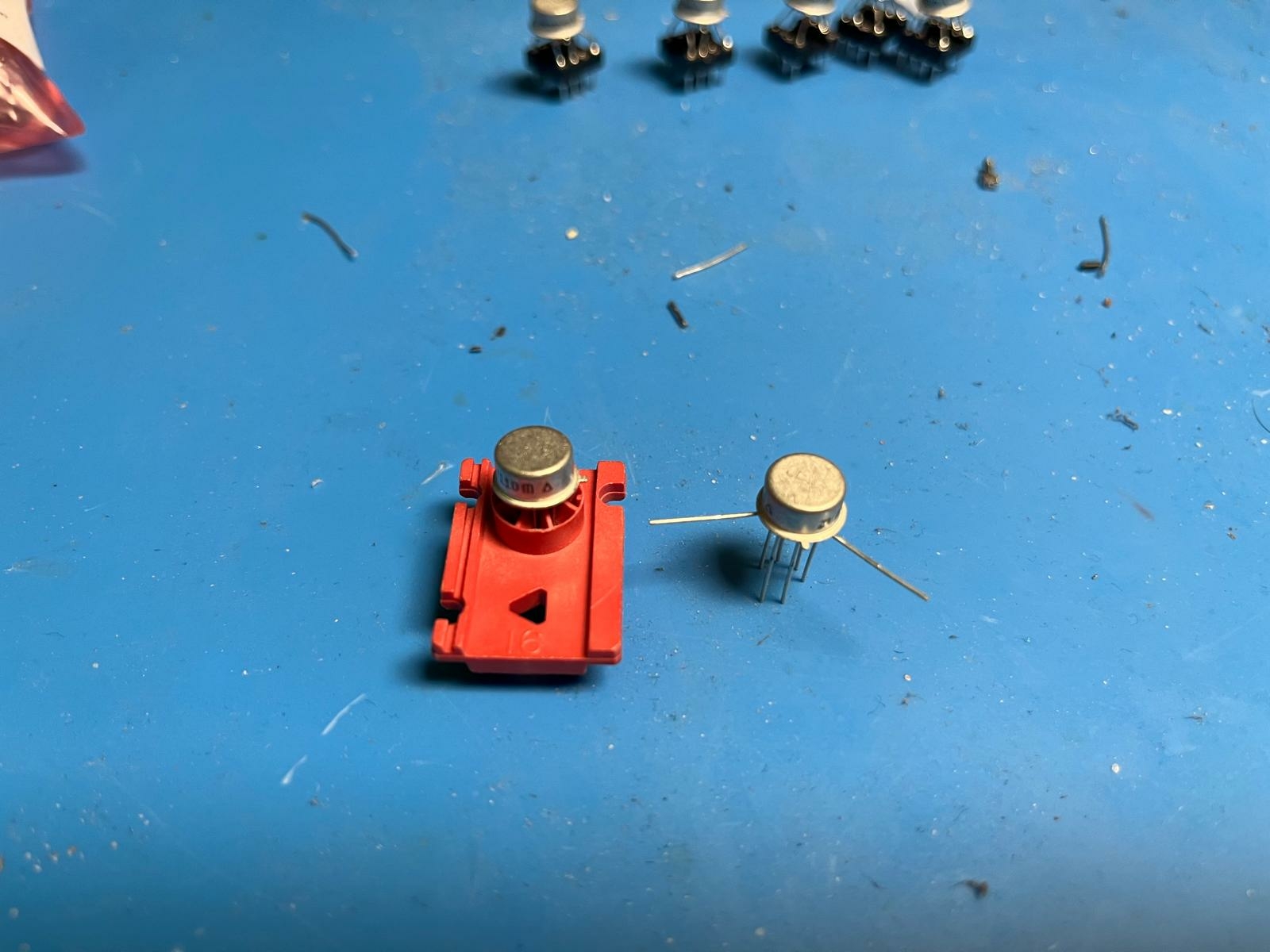
The 2504's were replaced with compatible AM2804 ICs. Since I did not want to pay out of the nose for these parts, I purchased chips in a metal can. It turned out surprisingly easy to bend the legs to fit in the sockets and they work just fine. Here's how I went about doing that:
1) Two of the Pins are not connected to anything. I started by taking the ICs out of the plastic carrier they came in and bent the pins out of the way.
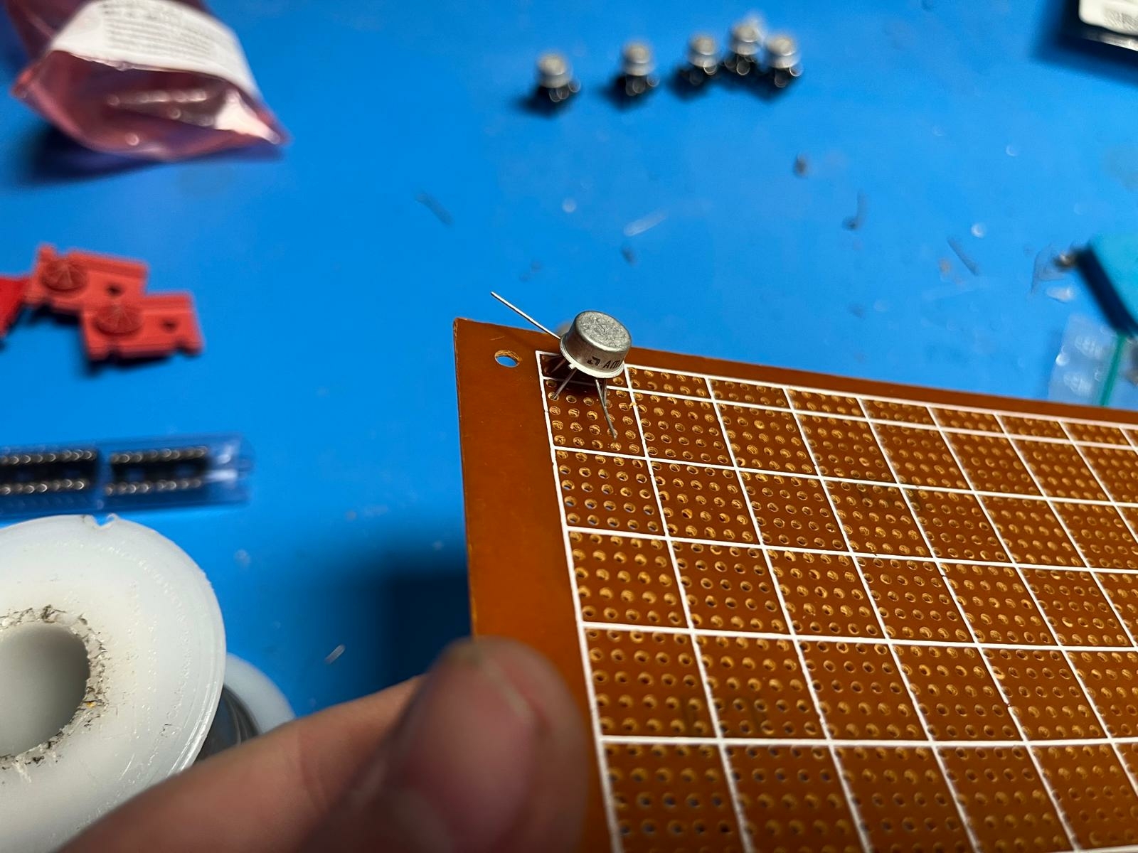
2) Making sure each pin landed in the right hole, the IC was pushed into a piece of protoboard. This was a little tricky at first, but went much smoother on subsequent ones. The trick is to notice that - as different pins need to span a greater distance to their respective hole - some of them want to go in first.
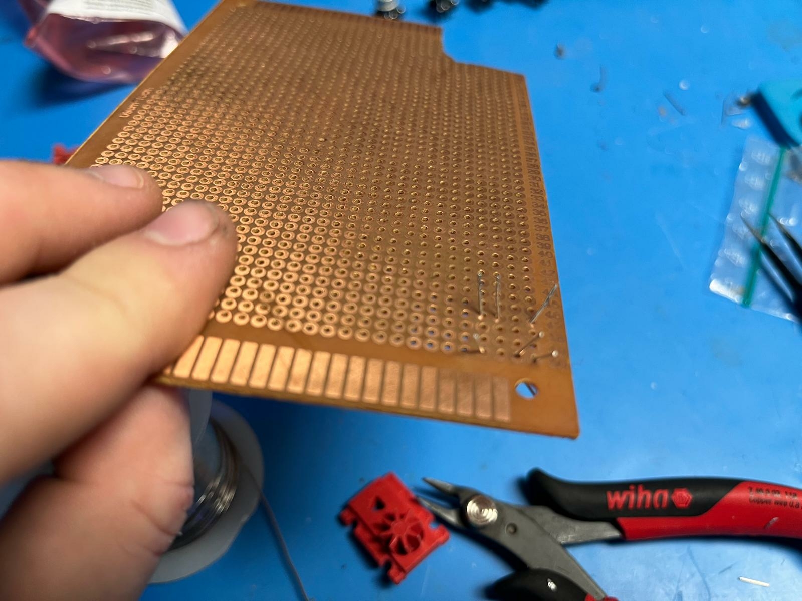
3) The pins on the bottom were then straightened out and clipped of so they were the same length. This is much easier to do before taking the chip off of the board.
4) The pins can then be easily inserted into a (nice, "turned pin" style) socket. The N.C.-Pins are clipped of close to the can. The legs of the IC fit well into the socket and I could have just left it like this, but I decided to solder the pins into the socket. This socket was not soldered into the motherboard but rather placed into a second socket which was permanently installed.
As I did more of them I got better at keeping the can directly centered on the dip footprint so that the ICs did not interfere with each other when placed adjacently.
It is pretty clear from the datasheets that the two versions of the AM2804 share the same die which is rotated differently (with the positions of the N.C. pins altered), making this easily doable.
I used this graphic as a reference. You should double-check my work if you are trying to follow these steps, but this worked for me.
Next was the 2519.
You may notice on the picture that nothing appears to be fitted in that location. Yet this setup works.
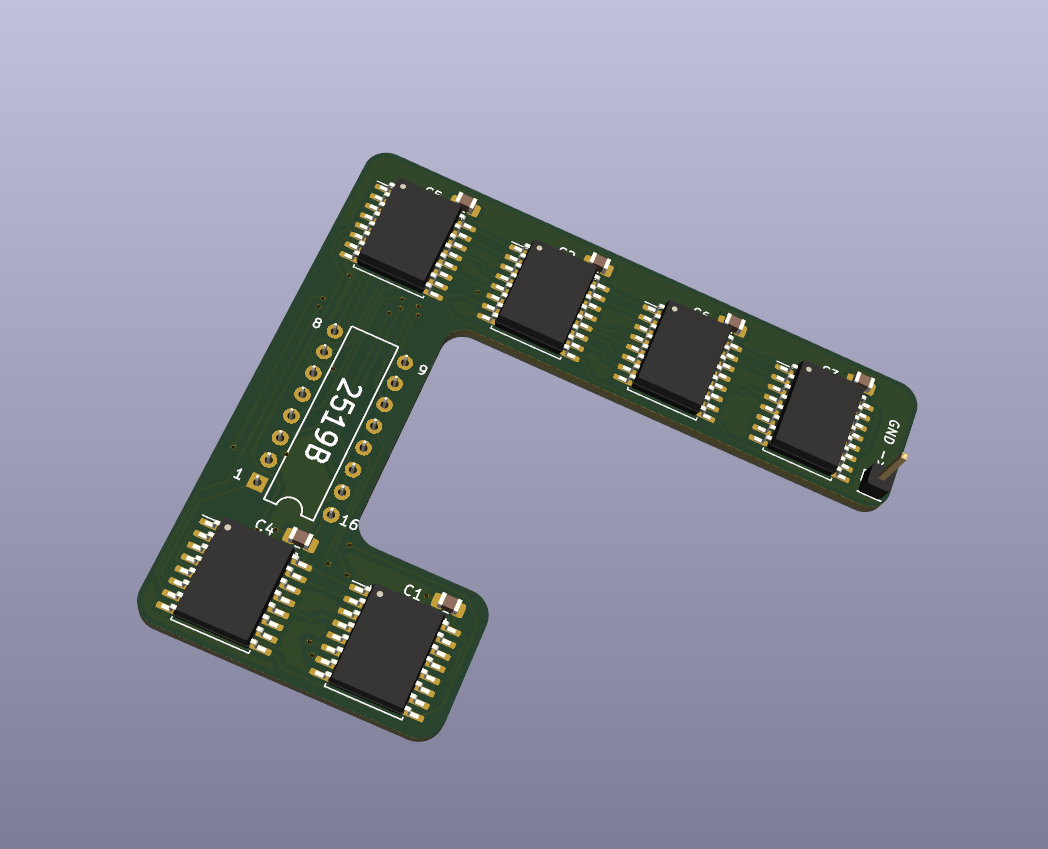
When planning this project two years ago it was apparent that this IC in particular was not obtainable at a reasonable price. I decided that I would follow the path of others on this very Forum and used six modern shift registers to replace this one IC. As I did not particularly liked the existing solutions which plug into the top of the motherboard I decided to design my own:
This PCB is soldered on the bottom of the Apple 1 motherboard. As the IC is not connected to Ground, a short wire is run to a pin of IC D1.
(I have uploaded the design files to a GitHub page)
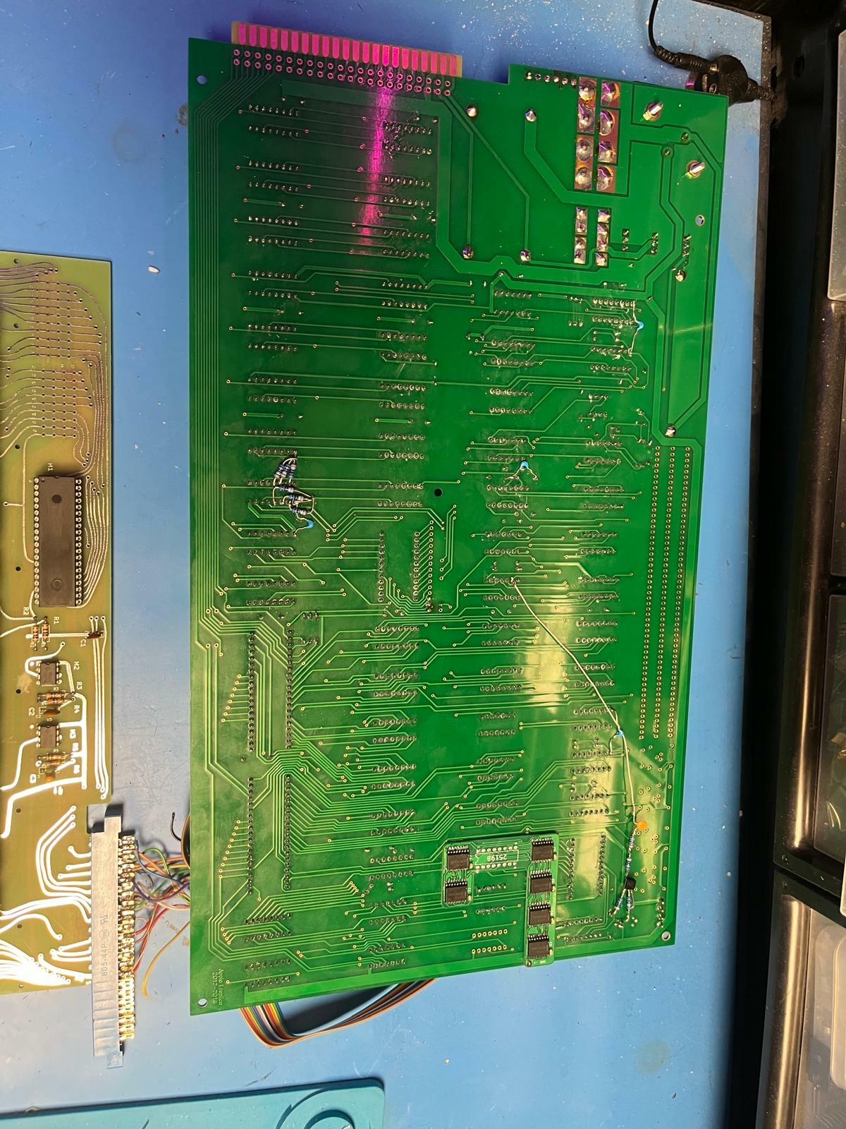
Here's a picture of the bottom of my Apple 1:
I have implemented the reliability mods outlined on this forum.
I also have performed the modification which fixes the vertical sync, as the Sony PVM i was using for a display could only sync to the signal when the video pot was turned quite far up - raising the video level so high that the monitor performed some sort of automatic calibration which gradually - over the course of several seconds - faded the video to black.
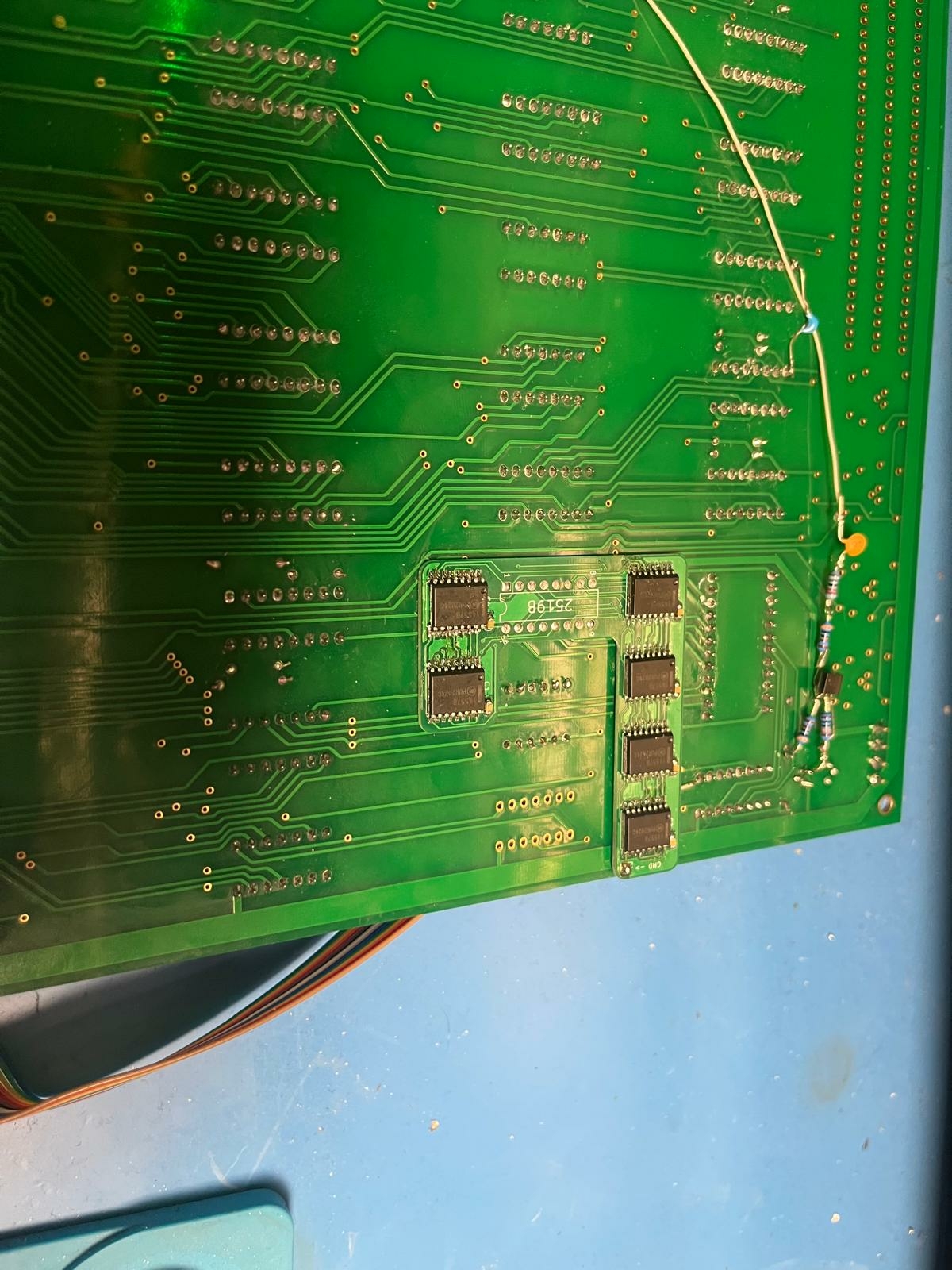
Here's a closer view of the daughterboard on the bottom of the motherboard:
(The Ground wire is run under the daughterboard to prevent pulling on the wire). All in all I am quite happy with this aspect of the build.
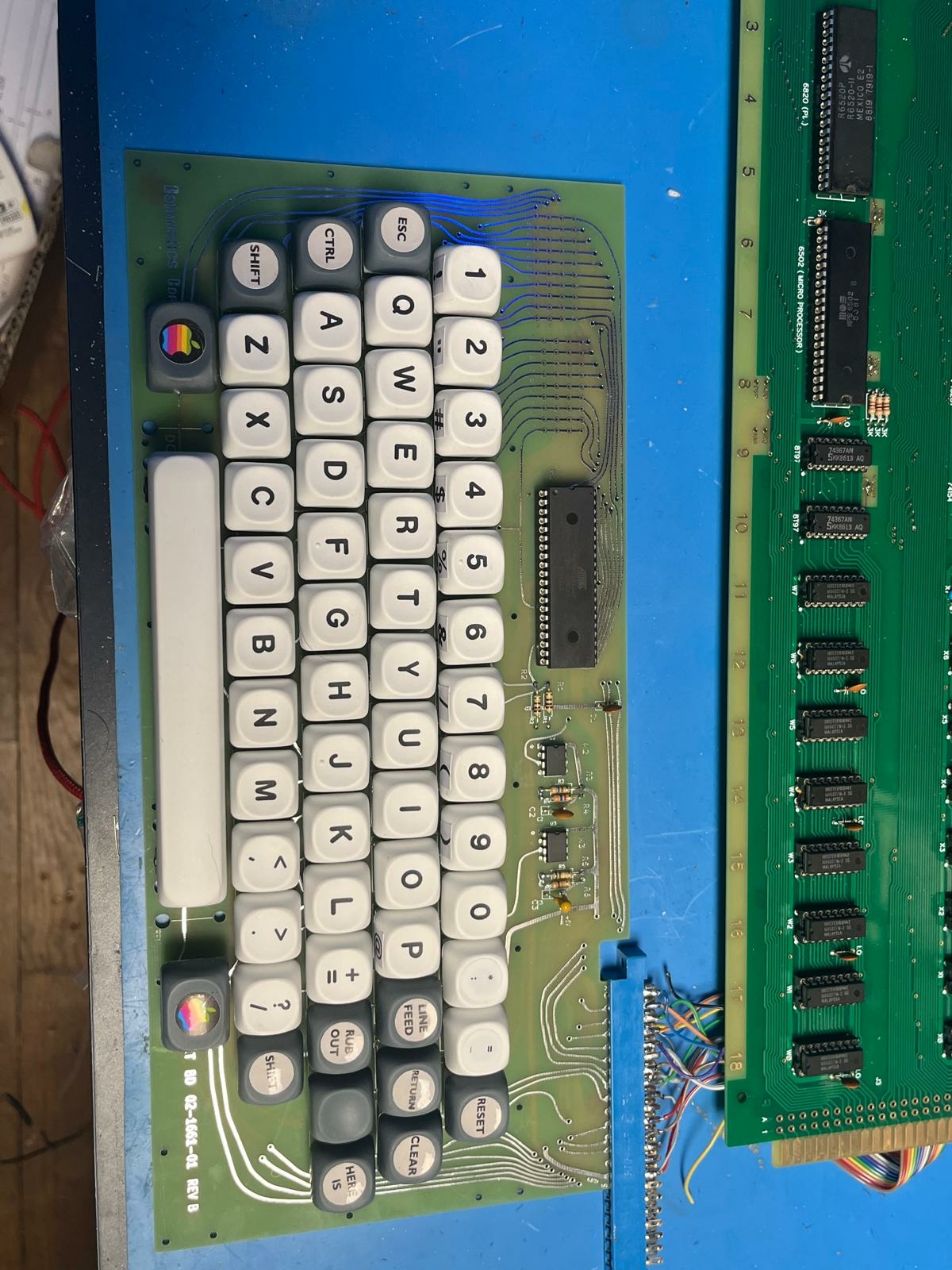
As a keyboard, I ordered myself the PCBs from this project, which is the replica of the datanetics keyboard with cherry MX switches. I'm still waiting for an edge connector of the correct size, but I didn't want to wait any longer.
I chose keycaps with a profile that is the same between all the rows, allowing me to mix and match them arbitratily.
As not all of the keycaps were present in the set (obviously), I re-labelled some of the switches after painting them.
These labels are printed on an inkjet printer and were cut out using one of the cheaper vinyl cutters. Mine has a small sensor which can scan the printed page for alignment markers which makes this sort of thing very convenient.
Time will tell how these labels hold up (I suspect that they might rub off quite quickly), but I don't really see this machine as being in use constantly so that might be fine.
I will finish this post with a few pictures of the computer in operation.
I am definitely going to build a nice case for it (my power supply setup is leaving a bit to the imagination right now) - and I have also yet to build the ACI.
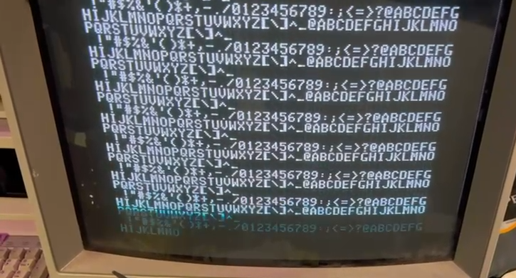
(before clear & reset - the video section is working perfectly. After installing the video mod the picture is centered horizontally and very sharp).
(Running the test program suggested in the manual, of which I have a printed copy that was supplied with the motherboard I bought).
A big "thank you" to all the users who posted helpful information on this forum, making this process fairly painless.

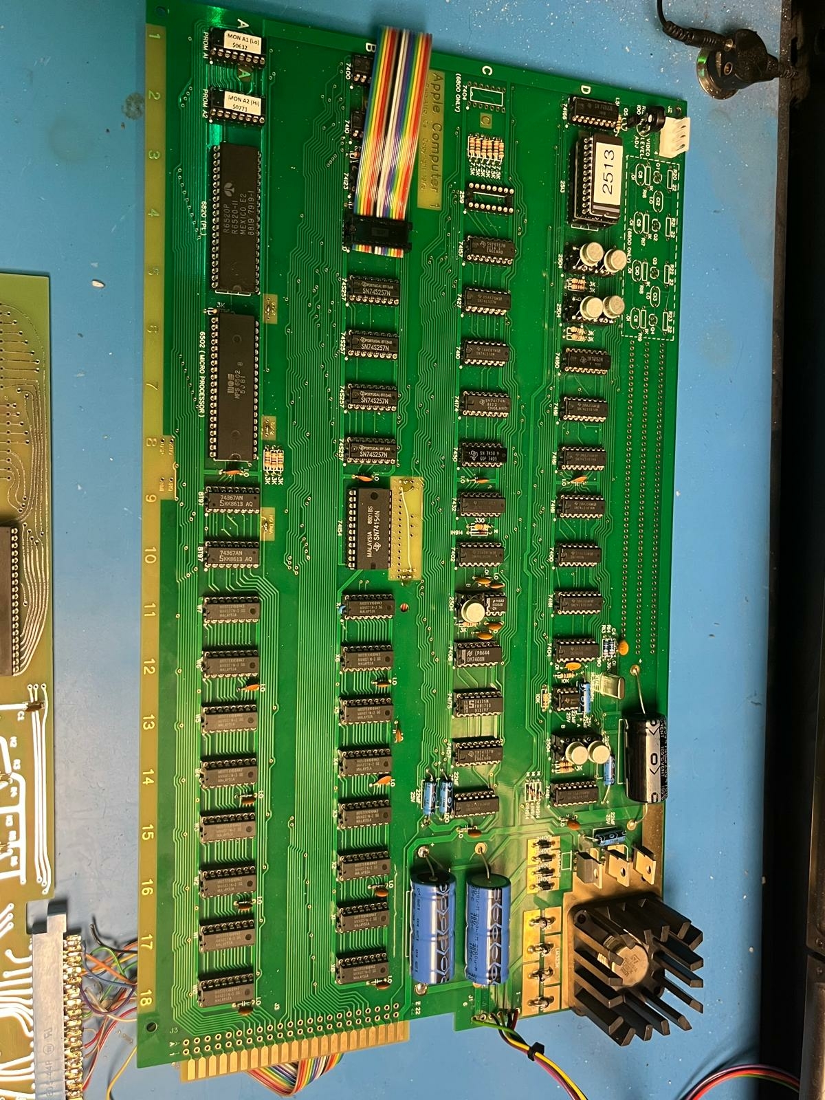



Your board looks cool, not quite like the original Apple-1, I'd say a bit hackerish! I really like your idea to place the replacement 2519 under the board, because the existing SMD replacement from P-Lab, for all its advantages, still looks a bit foreign against the background of the other parts soldered on the board.
I see you haven't installed a slot for expansion cards yet, what cards are you planning to use?
Hi JanFrederick !
First of all, congratulations for your 'newborn' Apple-1, each of those is an enrichment to the world and an ambassador for our hobby !
Your substitutions of the super expensive Signetics 2504, 2513 and 2519 are clever and thanks for showing the details, other builders not wanting to "pay through the nose" will embrace this alternative. When I hunted for the elusive 2504 years ago, I ran across an IC broker who had thousands of those in the TO can in stock, don't remember if there were from AMD, or Signetics, or National Semiconductor. I did not buy any because I feared that kit buyers would insist on the DIL-8 packages. But it is a valid substitution. IIRC, there where photos around from an original Apple-1 using TO cans, not sure if this was real (could have been a clone pretending to be an original) or whether the original DIL-8 ICs failed and were changed, or, worse, if that was a cannibalized original Apple-1 that had lost its 2504 and somebody used those in the TO cans to bring it back to life. Anyways, it's a valid substitution.
What you did not mention is where you found these. This info could be helpful for other builders.
The empty 2519 socket is no problem ... you could snip off the six output pins of a bad real 2519 in such a way that when plugged into the socket, they do not make contact. I happen to have lots of bad 2519 and would send them to any builder intending to use that trick just for the postage.
The 2513 is another topic. General Instruments and UMC made drop in substitute parts not needing the -12V supply (pin #1 is not connected in those). They should be still around at reasonable prices. Just keep looking ! (only the original Signetics ones with the grey package are all but gone).
- Uncle Bernie
The Apple-1 "Celebration" (#75) has TO can Synertek 1404As, but also has a number of unusual components (purple ceramic DRAM, lm323k heatsink, capacitors, diodes, yellow sockets) and is sort of a mystery as to why it is like that.
As one of the most likely options, I would assume that the owner got an unpopulated board and bought the components himself.
I've heard that some original motherboards were sold or given away as bare boards around that time and that Woz or someone at Apple had a stack of bare or partially populated Apple-1 boards in their office at Apple for years that pretty much any Apple employee could take one if they wanted it. I've also heard that Apple took back some Apple-1 on "trade in" towards an Apple ][ in the early days. During the early Apple ][ years there was little to no interest in the Apple-1 and nobody probably ever thought that some day they'd be a valuable collectible. Apple-1 boards back then people probably repaired or completed with whatever parts they could get ahold of. Which is kind of what is happening now because so many of the "original" parts are unobtanium now.
In post #6, 'softwarejanitor' wrote:
" Which is kind of what is happening now because so many of the "original" parts are unobtanium now. "
Uncle Bernie comments:
Sadly, this seems to be the factual truth, at least for those Apple-1 builders who "don't want to pay through the nose".
It is not that all these IC are completely gone, but once there is only one seller left in the world, the prices will go through the roof. For instance, there is a huge stash (thousands) of original Signetics 2519N at Manoshevitz Electronics in Israel, but they want $65 a piece plus shipping, and worse, in my experience, these have a high "death rate" during burn-in (some 25-35%), at least for those I bought from them before the price increase, more than half a decade ago. I think it's not fault of that IC broker that these ICs are so bad, I think the symptoms and conditions under which they die point to Sodium Ion contamination in the wafer fab, so it may have been from "bad" lots which were rejected by the OEMs or, once complaints were incoming, were "blocked" from sale by Signetics themselves. I still have a whole bag of these "bad" 2519N.
Yet another problem are the Chinese IC counterfeiters who can turn any old IC into any other type of old IC. These fakes typically are easy to spot because what they usually do is to apply a coat of black paint on the ICs to be "changed" (often after grinding off the original part #) and then they laser engrave the desired part number on it. And as long as the "new" IC has the same shape and form and number of legs, all is fine, as far as the fraudulent seller is concerned. So, buyer beware ... none of the 1970s era ICs in the Apple-1 ever had laser engraved lettering on them. It all was rubber transfer ink printed. However, sometimes, these Chinese IC counterfeiters duplicate this method, too. This is how an Australian Apple-1 builder ended up with "original counterfeit" Signetics 2504 shift registers in the original grey plastic DIL-8 package . . . these were re-stamped Signetics 555 timers which went up in smoke when the Apple-1 was turned on.
Some general tips & tricks for buyers of obsolete ICs
So, buyer beware. My policy is that I never buy ICs from Chinese vendors anymore, and if I buy ICs from American IC brokers, I demand proof of the chain of custody of the merchandize - at minimum, a guarantee that these ICs never left the United States in all the decades they were in storage. What you typically can find (and this is a good sign) is SMD ICs still in their original trays which were not fully used up in some production run back in the 1990s or early 2000s and which where then vacuum re-sealed in their moisture proof bag including a desiccant. Industry practice is to put a label on them stating date and operator when this re-sealing happened and when it will expire / needs re-opening and re-packing with a new desiccant. Solderability also is one of the concerns, and some OEMs do solderability tests from time to time, and when this shows signs of problems, these ICs are re-sealed and sold to IC brokers. Often, they get sold even without having any such issue - just because of technical obsolescence or end of production life of a product which used them. These are the "good" deals you need to look for when buying older ICs nowadays. But alas, the Apple-1 ICs are even older than that, no SMDs, so no pressing need for the OEMs to get rid of them via IC brokers before the solderability becomes a problem. These 50+ year old ICs are not used by any industry anymore anyhow. Apple-1 builders are the only users left. This is why IC brokers like Manoshevitz will sit on their 1000's of 2519N until the sun turns supernova in a few billion years from now. There simply is no market where 1000's of those 2519 could be sold to.
Here is my favorite obsolete IC search engine:
www.octopart.com
It will connect you to IC brokers wordwide (but avoid the Chinese IC counterfeiters !) but for best search results you need the complete type number from the IC manufacturer, including the correct prefixes and suffixes for speed grades, packages, etc. So some research using older data books is needed to find these type numbers. Of course it is also helpful to research and know drop-in substitutes from other manufacturers. Oh, and know the "extra codes" for mask programmable ICs like microcontrollers or character generators. Some IC brokers have no idea about this twist and may think that any old Signetics 2513 is the same thing. No, it ain't. This way I once got 200 pcs with the useless lowercase character set. The vendor took them back for a refund - another advantage of buying from American IC brokers (or for EU buyers, from EU IC brokers).
Good luck hunting for these ICs !
- Uncle Bernie
LOL! First, the Sun is not massive enough to ever turn supernova. Second, it doesn't look like this guy is just sitting on them:
2519N.png
I for one am glad that I made the mistake of buying counterfeit chips long before I ever thought of buying an apple 1.
I did contamplate buying one of the original chips from the above mentioned eBay seller, but the things I read on this forum convinced me otherwise.
The shift registers came from an eBay seller from greece, but the listing has disappeared in the 2 1/2 years since I bought them. I bought 8 of them and they came in the original chip carriers leaving their legs nice and straight. At the same time I also bought a DS0025 in the same package (I ended up using a DS0026 instead), which was simply pushed into a piece of foam and stuffed into an envelope. At least it wasn't styrofoam...
I am still waiting for the correct kind of connector for the ACI - the one I bought has the two rows of pins spaced slightly too far apart. I foolishly assumed that there would be a standard for that kind of thing, but apparently that is not the case. The perils of not checking the datasheets I suppose.
I have most of the parts for the ACI (except the ROMs), so I have been limited to typing in programs by hand for the moment.
Meanwhile I have been busy building a case for the Apple 1.
I decided early that I wanted the case to be a complete package - no external power supply or keyboard.
I also wanted to make it out of some sort of hardwood. At the same time I wanted the motherboard and the keyboard PCB to be visible.
103_case_34.jpeg
A few years ago I built a frame for an original Atari "Asteroids" arcade PCB which I repaired. From that project I had some 10mm Mahogony boards left over out of which I made the case's side walls.
The floor, front and back of the case were made from 4mm plywood, painted black.
I cut out all wooden pieces on my table saw.
The top two panels were CNC cut from 3mm thick polycarbonate. Since I don't own a CNC machine (yet) I ordered the clear parts online. They came out fine, although I forgot to round the corners on the keyboard panel.
102_case_front.jpeg
The top panel slides out towards the back of the case (it has a thumb-hole to make that a bit easier). The front panel is inserted on one side and flexes enough so it can be inserted on the opposite side, neatly falling in place around the keyboard.
(The gap visible on the pictures between the panels can be closed by adjusting the back panel.)
As I planned the entire thing in CAD I could make sure that the cutout around the keyboard fit perfectly. You almost can't see it in some of the pictures.
I took apart my temporary power supply and relocated the parts into the new case. One of the transformers is mounted on its side to the back wall to save on vertical space. The LEDs were inspired copied from Eric Bruchez's build which he covered on his website.
There is a fuse on every secondary of a transformer.
The transformers used are:
- Christiani 64468 (+/-14V)
- Block VCM 50/1/9 (9V)
(Both are 230V on the primary side)
105_case_detail.jpeg
The 28V transformer has a 8V secondary output which is too weak to power the apple 1. I used some spare diodes and a large capacitor to build an unregulated 10-11V DC power supply which feeds two warm white LED strips on the inside of the case. I might add a diffusor or some angled aluminium brackets to hide them later. This voltage also powers the fan, wich is a Noctua NF-A9 FLX. The fan came with some passive adapters to make it spin more slowly (and thus, quietly), but since I am under-volting it anyway that was not necessary. The fan is very quiet but does move a nice amout of air. I will monitor the chip's temperatures the next few times I use it with the lids closed.
(plus I think the beige and brown color scheme works very well for a device this old.)
Here's what the back looks like:
104_case_back.jpeg
I used an old-school label maker to label the back.
The slot below the fuse holders is to provide a path for the air moved by the fan to exhaust.
Only later did it occur to me that I would have to add the cutout above the LEDs so I could still remove the top panel.
Finally: here's a picture of what the case looked like in the computer:
Screenshot 2025-05-08 212250.png
I exported the keyboard PCB from KiCad as a 3D Model and imported it at 1:1 scale into the CAD software. I traced the silkscreen around the keys and offset the lines outwards by a few mm.
From that model I created a mechanical drawing:
Screenshot 2025-05-08 212441.png
As you can see, my Apple 1 is quite large - I suspect most cases were / are smaller. I decided against rotating the PCB and / or placing the keyboard above it so as not to obscure the PCB - at the cost of desk space I suppose.
I'm quite happy with the way this came out (even though my woodworking skills are limited. I am quite proud that the CNCd pieces fit on the first try - other than the slots in the side panels being slightly too tight).
Now I'll only have to find an appropriate monitor...
P.S.: Space will indeed be tight for the ACI, but it should just about fit.
In post #9, 'JanFrederick' wrote:
"... I ended up using a DS0026 instead ..."
Uncle Bernie comments:
Oh yes, for the DS0025 you pay through the nose, too, if you can find them. DS0025 is a very old MOS gate driver from the early 1970s and before that one, in the 1960s, there was a MH0025 which looked like a monolithic IC (in TO can and in DIL-8) but actually was a hybrid circuit: a few diode and transistor chips mounted on a ceramic substrate which had thick film resistors printed on it. This is why the DS0025 has such a primitive circuit inside.
Much of the problems I had with my first Apple-1 build some 6 years ago came from the use of the DS0026 in lieu of the DS0025. This was one reason why my plan to build 100 wave soldered Apple-1 was abandoned (you can't sell stuff that does not work, except if you are from mainland China). At this time I did not know that the DS0026 switches so much more current so much faster than the DS0025 that the weak power supply traces of the Apple-1 PCB could not take the beating, and DRAM operation was compromized. The only remedy I found is now known as "Uncle Bernie's Apple-1 Reliability Mods", but this is just a more tedious exercise than the half a dozen capacitors an Italian Apple-1 builder had found to fix his Apple-1 (it could not fix the mine, but improved things - I had to add more capacitors). My discovery and analysis of the reflection issue on the multiplexed address lines (remedied by adding the six damping resistors) came later. As it turned out, with robust DRAMs (Intersil were the most robust) and when using a MH0025 or DS0025, but not a DS0026, just adding the six damping resistors would give builders a robustly working Apple-1.
I once got burned by Chinese DS0025 counterfeits which turned out to be some industry standard MOS gate drivers made in a CMOS technology which are meant to drive the huge capacitive load of modern power switching MOSFETs (nanofarads) quickly. These have the same footprint and function as the DS0025/DS0026, but source several Amperes in a few 10's of nanoseconds. Any Apple-1 (even with all the added capacitors of the 'Reliability mods') will collapse under such fierce beatings. I found out that adding 33-75 Ohm series resistors (I used 0805 SMD) in the PHI3, PHI4 outputs would tame these modern CMOS drivers so much that they work fine in the Apple-1. These drivers are still in production. You only need to watch out for those who can only take 12V or 15V supply voltage differentials. Apple-1 has 17V supply voltage differential on these drivers. Also, on some of those CMOS parts, you need to add 10k pull down resistors to the -12V rail to give their inputs proper DC bias. Only a few of these CMOS parts have these resistors built-in. There are countless variations of these drivers out there. Almost every power MOSFET switch in automotive applications used them (just if you are curious why, there are certain generations of power MOSFETs which will die if turned on or off too slowly --- these comprise thousands of individual MOS transistor cells and all the threshold voltages of all the cells follow a statistical distribution, so unless you turn the gate voltage on and off quickly enough, a subset of those cells will take all the current and die from that. This was exacerbated when they cranked up the gain of these MOSFET cells too much and reduced the threshold voltage (for a lower rds,on) such that these individual MOSFET cells became thermally unstable, same as with any BJT - at this point in "technical progress" these MOSFET started to die like flies, unless turned on and off really quick and sharp - and you could not use them as linear regulators anymore - "progress" ?).
So this is the MOS gate driver story. As there are plenty of drop-in alternatives (when using the added resistors) I never considered them to be rare and critical.
- Uncle Bernie
I am late to this thread, but congratulations on your Apple-1 build! I especially like the hidden 2519 substitute! We had discussed with Uncle Bernie the possibliity of trying to place a non-working 2519 on top, and see if things would work. This would be good for looks.
What would be a nice thing to have for such applications would be completely dummy chip packages with no internal connections and blank so could be printed with whatever on top to look authentic.
This fake cache RAMs would be a good candidate Youtube Link Fake Cache RAMsyou might need to short them to fit into the socket.
Maybe @UncleBernie can help he has a bag ful of none working chips, if you take very slightly pointed drill bit or a Dremel it should easy to drill the chip die away from behind.
If someone has a an appropriate laser like in the video do the same technic from the back side.Youtube Link Laser chip case removal
In post #14, 'natas666' wrote:
" Maybe @UncleBernie can help he has a bag ful of none working chips, if you take very slightly pointed drill bit or a Dremel it should easy to drill the chip die away from behind. "
Uncle Bernie answers:
Sorry, folks, all the bad 2519N I had have been spoken for and they went to several people who asked for them in the past weeks. Today the last dozen will be sent to a guy who lives in Silicon Valley - along with 100+ bad MM1404 shift registers. He told me that they will be used as dummies in the upcoming Apple-1 clones built by college students. Nice project !
It's like with any other offer I had (or still have), it's my own hobby leftovers / excess, and before I throw these leftovers in the trash, I seek people who can put them to good use. When they are gone, they are gone. And it has been so simple to get them - I always suggest "Send PM" . . . this is the button which appears under the poster's name when you are logged in.
DRILLING OUT A DIE IS A BAD IDEA
I think it's also a very bad idea to try drilling out an IC "die" from a package to get a neutral dummy. In the semiconductor industry there is a method called "scoop and goop" where they open the package from the top to take out the die and then place it elsewhere and re-bond it. But this involves a special etching technique with an hot acid stream squirted on by a controlled flow pump and it leaves a crater in the package. This is usually done inside a special machine.
If you try to take a die out with a drill press, you would need to work from the bottom and it won't work without causing damage (pins may become loose). A drill bit exerts too much point forces, regardless what you do - it will bite into the different materials in uncontrollable ways and the intentional "play" of the drill bit is a problem, too --- if you use a milling machine there is no such play. But a drill press has it. Instead, you could try a diamond dust coated grinder bit in a drill press and work very slowly with a lot of flushing (compressed air might do instead of a flow of cutting fluid) to grind into the IC package from behind. If this succeeds to remove the die and the bond wires without making shorts is another question.
The best method may be the one I suggested: use original ICs of the same type which are bad / limping and just snip off the outputs which have a functional problem. If you use the machined contact type sockets then it is easy to snip the pins such that these have a small gap so that they don't make contact, but still look intact when casually looking from the top.
This is based on the assumption that the 'limping' IC doesn't draw excessive current and doesn't overload any input by drawing current - this would indicate a catastrophic failure of that IC, and it would be unwise to use it (it's a fire hazard).
But most "bad" 1404, 2504, 2519 I ever had just have internal failures in the shift register matrix ... or some problems with their output drivers being too weak to establish proper TTL logic levels on the load resistors needed for these ICs.
IIRC, back in the day when the 1404/2504 shift registers came on the market, they were known to be finicky and to suffer from various functional problems ... such as pattern sensitivity, some bit patterns would cause bit flips. The reason is that these primitive dynamic shift registers were the first PMOS products they tried to make, and worse, even later they would be used as "pipe cleaners" after incidents in the wafer fab. This is because unlike the more irregular LSI chips of the time (such as calculator ICs) these shift registers had a very regular structure which allowed the fab operators to visually check the success of their corrective measures with the optical equipment in the clean room itself - for instance, any defect in a sea of the same regular structure can be spotted quickly by the human brain. Try this with irregular structures ... it will take much longer, if you can find it.
But now, all the bad ones I had are gone ... and I hope the new owners will succeed using them as dummies.
- Uncle Bernie
P.S.: The only items I have left right now are the A2-A1 keyboard adapter kits, $2 plus postage each (no profit, I just cover my costs, and no, you can't make them at this price, they were economically viable only because they share space on a multiproject PCB). Here is the link:
https://www.applefritter.com/content/smallest-a2-a1-keyboard-adapter-pcb-world
And the multiproject PCB can be seen in post #4, my response to a guy who asked for the Gerbers. Sigh. It makes no sense, making them would cost you a fortune compared to the $2 I ask for my leftovers from that multiproject run.
- UB
I did not know that thanks for the correct UncleBernie.