
| Attachment | Size |
|---|---|
 Figure1.jpg Figure1.jpg | 373.79 KB |
| Figure2.jpg | 328.58 KB |
| pcb.jpg | 442.03 KB |
Hello everyone, I encountered some issues while working on the Apple 1.
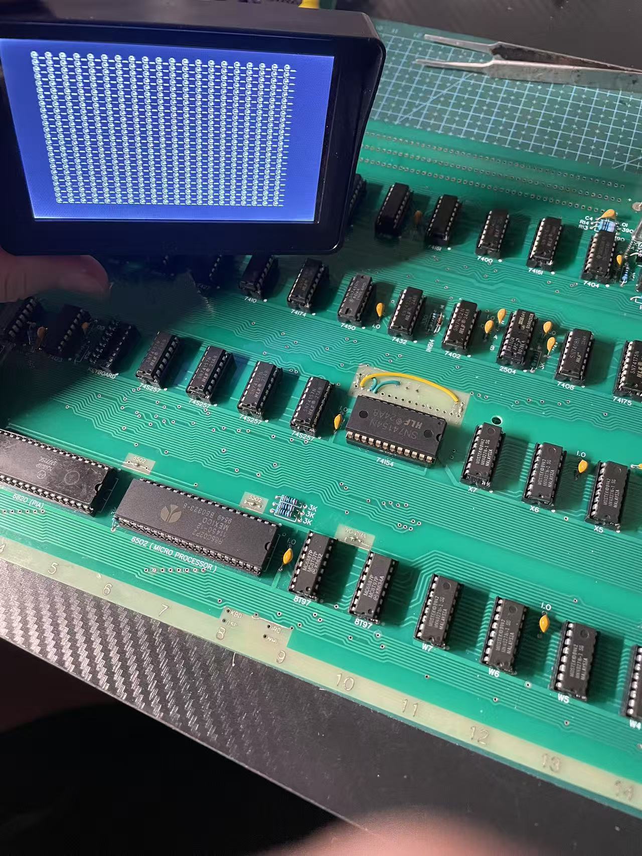
1:It powers on and displays "@_@_@_@_" but does not blink (Figure 1).
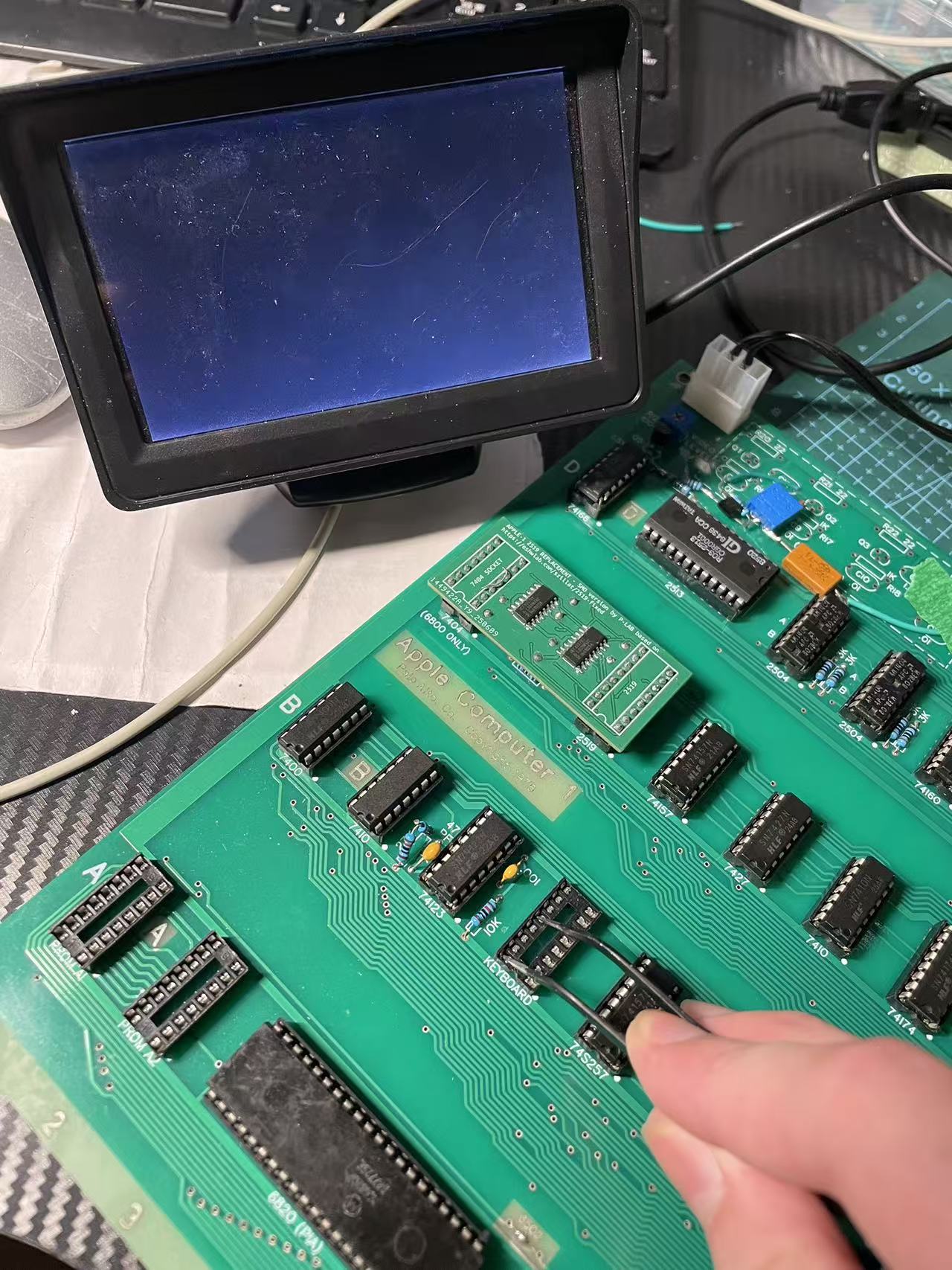
2:When I press the clear screen key (B4-12 connected to 5V), the screen does not display anything. When not pressed, it shows "@_@_@_" (Figure 2).
Except for the 7450, all the other 74-series chips are from the Chinese manufacturer HLF.
That does not look too bad.
Terminal sections seems to work basically, you get an alternating pattern of "_" and "@" that is very good and that clear screen works, that is also good.
Looks like it's really only the blinking that is missing.
I even would assume more will work, just with a none blinking cursor.
You need to check the output of ICD13 (NE555) on Pin 3 it should alternate 150 ms low "@" and 300 ms high " ", and cursor frequency is around 2,18 Hz
Are R10 and R11 10kOhm and C7 22µF ?
What measurement equipment do you have availible?
A DigitalVoltMeter is often to slow, to show the blinking, an analog Voltmeter will show that fine.
If a DVM is all you got please connect a LED with a 1KOhm resistor as pictures above to Pin 3 and Pin 1.
The LED should be lit when " " is shown and off when "@" is shown".
At the moment I would expect the LED staying off, if that is the case and R10 and R11 are in 10kOhm and C7 22µF the NE555 is likely broken.
I see the PROMs are not populated do you have any external ROM replacement?
When the CPU part is working a press on Reset after Clear Screen should show "\" first postiion first line and the a Cursor "@" should be blinking in the first position of the line 2.
You can compare with this: https://www.scullinsteel.com/apple1/
The 74xxx parts are quite uncritical but the 2513, 2519 and 2804 parts are hard to get in working, none fake condition.
But yours seem to work at least as far we can tell with the information that you provided so far.
It would be nice if you let us know from which country you are because here are people from all over the world, and it can be very helpful if you find some one with another Apple 1 in your country.
Hello, I am a student at a vocational school in China.
I used 10 kΩ for R10 and R11, and 22 μF for C7.
The NE555's Pin 3 shows a frequency of 10 Hz when measured with an oscilloscope (Figure 1).
I am using a PROM adapter board from P-LAB (Figure 2).
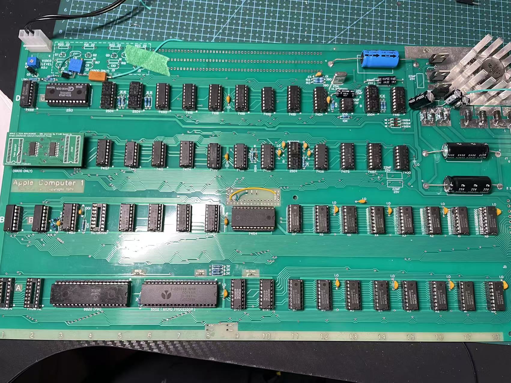
After replacing R10 and R11 with 2 kΩ and C7 with 100 μF, the issue remains unresolved (Figure 3).
I have an oscilloscope with an analog bandwidth of 30 MHz and a maximum sampling rate of 200 MS/s, a logic analyzer made with a Raspberry Pi Pico with 22 channels, and a digital multimeter.
Figure 1.jpg
Figure 2.jpg
Figure 3.jpg
So myguess Japan, that I took because of the nickname, was wrong, but at least asian region was correct.
10 Hz is a fast flashing that would look more like a gray @ instead of a blinking one.
2kOhm, 2kOhm and 100µF you selected should result in 2.4 Hz with 280 ms high and 120 ms low https://ohmslawcalculator.com/555-astable-calculator
It seems your NE555 behaves strange, do you have a replacement?
What you can do, take the NE555 out of the socket, take a 2k resistor and bridge pin 3 via the resistor alternating to pin 1 and pin 8.
In other words blink manualy.
Does that work?
My 2 cents: I've built probably a dozen Apple-1s and on none of them did the startup grille blink on first startup. The blinking appeared after 3-5 minutes of operation and never went away if I used my replica at least once every 2 weeks. Later I realized what was wrong, my Philips 22uf capacitors were almost dead and showed very low ESR.
I tried these two methods (replace NE555 and generate pulse manually with 2K resistor), but the problem still does not flash is related to my AM1404 or 2519 adapter board
You said when you press clear or simulate that with shorting two pins the screen wents black. If that is the case almost certainly both the line 2519 and the 6 screen character buffers are working.
One question if you stop pressing Clear the screen stays clear or instantly fills again with the @_@_ pattern?
If the pattern comes back it means something is wrong with the the AM1404 or the DS0025.
There is one AM1404 that stores the cursor position C11B.
Question is does the reaction change when you remove that one?
If you exchange it with one of the other Am1404 does everything works same or no change?
Here is somewhere a thread that describes in more detail what happens when certain chips are missing or broken.
So far we can only say the bits used by @ _ and Space seem to work.
Could you adjust the blinking to 2Hz?
If yes, follow the signal it enters C12 on Pin 1 and leaves it on Pin 3. It enters C10 on Pin 2 and leaves it on Pin 1.
Where does it stop pulsing?
I would recommend to build a Tester For the Am1404/2804 https://www.applefritter.com/comment/112595#comment-112595
ne555pin3.jpg
0025pin5.jpg
00255pin7.jpg
The Output of the DS0025 does not look good at all.
But you set the timebase to 1sec per devision that will give random results!
The Clock we want to observe has the frequency of half the Character Rate.
14.31818 MHz (Crystal) divided by 2 (C13) gives a Dot Clock of 7,15909 MHz
The Dot Clock divided by 16 (D11) is 447,744 kHz what means a periode of 2,233 µs.
To see something useful the timebase needs to be set somwhere betwenn 1µs and 10µs per devision.
This estimation ignors the the border and traceback times.
Bild_2025-08-29_102541322.png
Confusion alert: what is called on the picture above ø1 and ø2 is called on the Apple Schematics ø3 and ø4 as the other clocks two are already assigned to clocks used by the CPU.
On Pin 7 and Pin 5 you should see a signal like above.
This signals are switched off when the video Signal is drawing the boarders or is in the trace back phase.
The outputs of DS0025 are not TTL the signal oscillates somewhere between -12V and +5V, nominal -11,3V and 4,3V ! Your Y-scale of 5V per devision, should be fine.
I don't have a Apple 1 so I cannot do reference measurements, sorry.
To your first picture that looks like we have a flashing of around 2,5-3 Hz that is a bit faster but should be visible.
Here you find some hints what happens when you pull specific chips: https://www.applefritter.com/comment/112475#comment-112475
But as first recheck the DS0025 output with proper settings.
The DS0025 controls the clock of all seven DIP-8 shift registers with out a propper clock they can not operate. And the output would be fixed as they do not circulate.
Your 2519 Adapter Board and also the 2513 Adapter Board is with a certainty of 99% working perfectly.
If the 2513 would not work screen would be filled with white stripes or black instead of with @_@_.
When the Clear clears the screen as long as the connection is hold then the 2519 works as well, it's also needed to display a full characters if it is not working you would see broken characters.
So please assume this two parts are working perfectly.
0b154b65564220e7f0f22ce11b563379.mp4
It's absolutely possible that you have a problem with C13 or C14 too that prevents the blinking but
C14 Pin 12 Zd toggels between Pin 14 IOd (GND) and Pin 13 IId (Cursor) depending on the state of Pin 1 S (/WRITE)
That is some kind of a Chicken Egg problem, as the cursor is need to generate /WRITE.
The cursor is stored and circulated around in C11B if the the two clock signals are not working that does not work as well.
So please check if DS0025 is producing the two clock signals if it does not all AM2804/2504/1404 chips including the cursor are working.
Please have a look to Pin 13 of IC14 if that is high or toggeling between high and low you can do the following:
Bend Pin 1 of c14 out of the socket you can connect it with 1 or 2k resistor with GND (low) or 5V (high).
Depending of that the logic level of Pin 13 (Cursor) or Pin 14 (low) gets output on Pin 12.
If Pin 13 if C14 is always low C13 74175 might be broken or more likely Pin 13 D3 has a constant level what would be caused by C11B.
It can be a broken 2504/2804/1404 in position C11B or the missing clocks (you guessed it) on the output of the DS0025.
In the Video you flashed the Vertical Blanking Signal that generates the borders that signal is or-gated with the CLEAR input and send as CLR to Pin 15 of C4 and C14.
In other words outside the visible 25 lines the CLEAR button is automatically pressed.There for we can assume that both 72157 at position C4 and c14 work fine.
Okay, then should I go check the part about ds0025 next or go check these two ICs, c13 and c14? I think I should check ds0025 first. What do you think is more appropriate?
First you check if the inputs of the DS0025 are toggling. Actually you are checking the parts above on the schematics. If you have something on the input you can expect having also something on the output so the idea is to measure input and output same time and compare on a dual channel oscilloscope.
Hi natas666,
I finally have some time to work on my Apple‑1 again. Following your earlier advice, I built a tester for the AM1404 shift registers. The good news is that all 7 AM1404 chips on my PCB appear to be working correctly. When I press the reset button, the red and green LEDs on the tester flash together for a moment, and then the green LED stays on steadily, which I believe indicates they are all functional.
Now I’m moving on to check the DS0025 section, as we previously discussed that its waveform didn’t look right. Do you have any specific suggestions on what to probe or look for with the DS0025?
Also, I’d really like to better understand how the terminal section works. Do you have any documentation, guides, or tips you could share that might help me understand its operation? By the way, I won't be able to buy a dual‑channel oscilloscope until the end of this year, so any advice that doesn't rely on one would be especially helpful.
Thanks again for all your help—I really appreciate it!
Hi Moyong
Any markings like 2/2/2 underneath your DS0025?
If so only the second half of the IC is working, seems they left the factory that way.
In post #16, 'moyong' wrote:
" Do you have any specific suggestions on what to probe or look for with the DS0025 ? "
Uncle Bernie comments:
Look at PHI3 and PHI4 with an oscilloscope (pin #7 and #5 of the DS0025). These should swing between -12V (active phase) and +5V (inactive phase), and the active phases should not overlap (in other words, if one of them is at -12V, the other one must be at +5V). If they fail this test, there are two main reasons:
1. The driver logic (IC @C12 pin #11 and IC @C10 pin #4) does not work correctly. These should show TTL swings where the "H" phase is the active one, as the DS0025 inverts. So no overlap on this pins of the "H" level allowed.
2. The DS0025 is a fake. Most DS0025 you can source from mainland China are fake. If laser engraved, certainly fake. Try the Acetone (aka "nail polish") test with a Q-tip on the surface, if black paint comes off, it's a fake. National Semiconductors did not have laser engraved DS0025 or DS0026.
What these Chinese counterfeiters do is this: they re-label industry standard MOSFET power switch gate driver ICs which have the same footprint and function as the DS0025 / DS0026, but they are much, much beefier (much more drive current capability) than the originals. And they have CMOS inputs which do not have the ~250 Ohm pulldown resistor on the inputs (pins #2 and #4 on the DS0025) to the negative supply voltage (pin #3). You can easily verify if that resistor is there by an ohmmeter. Allow +/- 40% tolerances (yes the 1960s era bipolar processes were that bad). If you don't find the resistors there, it's a fake.
Original DS0025 (or MH0025 which has the same function) are incredibly difficult to find, but DS0026 and MH0026 will also work if you put in all the "reliability mods" I have published on Applefritter in another thread a few years ago. This involves adding a lot of bypass capacitors. I've found that adding these bypass capacitors to make the Apple-1 work with a DS0026 can be avoided if you add 33-51 Ohm series resistors on the outputs of the DS0025, but as this involves trace cuts on the Apple-1 otherboard and hence is ugly. And it's not guaranteed to work in all cases. But, by adding such series resistors and 10kOhm pulldown resistors on the pins #2 and #4 of a "fake" DS0025 I was able to make this "lab rat" Apple-1 work, just to prove that it can be done. The problem with these fake DS0025 is that most are not specified to run at 17V supply. Most are only specified for 12V supply. A few earlier types typically found in automotive applications were specified for 16V supply and the absolute max rating was a few volts higher than 17V they see in the Apple-1, so they could be used in it without blowing up too soon.
But it's an ugly situation. Somebody should make a small PCB with a DIL-8 footprint having a few small SMDs on it (SOT323 transistors, and 0605 passive components) which replaces the DS0025 completely. One channel would need a PNP, a NPN, two resistors, and two capacitors. Two channels would easily fit on such a small PCB but hand soldering would be too difficult for most people.
- Uncle Bernie
6b8416750232d8dff633e5c16516b713.jpg
35888577c4c99a5efff2c25bf4d327d4.jpg
C13#9.jpg
C12#11.jpg
The DS0025 I bought on eBay has markings that look printed on, rather than etched.
I can draw a simple PCB, but I would need a schematic to do so.
Could you please share the link to the thread about your "reliability mods"?
Thanks again!
Hi Moyong
Unfortunatally the 2/2/2 markings would indicate that the chip will not work in an Apple-1.
https://www.facebook.com/share/p/17j1AByN3r/?
Sarnian
In post #20, 'moyong' wrote:
" I can draw a simple PCB, but I would need a schematic to do so. "
Uncle Bernie comments:
You can find the circuit with the NPN, the PNP, the two resistors and the two capacitors in the Apple-1 schematic diagram for the "Processor Section", area B-7. This is a well known, canonical circuit for clock level translation / driving larger capacitive loads seen in MOS clock inputs. The only change you need to make is to tie the low supply to -12V instead of VSS, and if you want, you can leave out the 22 Ohm emitter resistors R20-R23 and the power supply bypass capacitors C12 and C13, because the former are not absolutely required for the DS0025 subsitute and the latter are already present at the DS0025 socket. Still, if you intend to make a small PCB which needs SMD SOT-23 transistors and 0805 sized resistors and capacitors, and if you have space left for these 22 Ohm resistors, leave them in but use 39 Ohms ... they can help to mitigate current spikes caused by the 1404 shift registers. Which was one ill effect in the Apple-1 that is latent with a real DS0025 but gets worse with a DS0026 as it is "stronger" - DRAM errors are a typical consequence of using DS0026 instead of DS0025.
If you want to try it out, you could either build the clock driver on a small perfboard using leaded components, and solder the six wires to the empty DS0025 socket, or you can cut the VSS trace and the trace from 7400@B1 pin #3 to the on-board clock driver, and also the output traces from the R20-R23 resistors to the microprocessor (but cut near the resistors). Then populate the on-motherboard clock driver, hook it up, and you have replaced the DS0025 without making an extra PCB.
There is a certain irony in all this clock driver business: the original 6800 was built on a process technology which was unable to drive its own two phase clocks, so the designers of the 6800 decided to use an external clock driver, and there even was a hybrid circuit available which looked like an IC but contained a small ceramic substrate with thick film printed resistors and individual BJT die attached and gold wire bonded to it. Same circuit !
IIRC, this hybrid did cost $50 (or so) in the early 1970s, which is about $400 of today's US$. For a clock driver, mind you ! No wonder that Woz put in his own clock driver cobbled together from discrete components. If you use modern SMD components bought at qty 100, your BOM except for the PCB would be about $0.80 for two channels.
Here is the link to the reliability mods:
https://www.applefritter.com/content/part-path-towards-rock-solid-apple-1-builds
Note that over the years, hundreds of Apple-1 were successfully built with a subset of these mods, but the six damping resistors are almost always needed to get reliable DRAM operation (see post #29 in that thread). Some people criticized me for "overkill" but when my first Apple-1 build did not work reliably and had huuuge issues, I just threw everything I had in my lab, including the proverbial "kitchen sink", into the solution, and my next build worked perfectly reliable all the time. The "cheapening" of the reliability mods - reducing them step by step - came in later years. The viability of using a smaller number of added bypass capacitors strongly depends on the type, brand and date code of the DRAMs - some are more sensitive to power supply pollution then others - and it also depends on the performance of the bypass capacitors chosen to populate the motherboard itself. But there is no "foolproof" recipe for that. It has to be tried out, so for each batch of DRAMs and bypass capacitors I could find, I had to build yet another Apple-1 to qualify them for my kits. This is part of the "secret sauce" why my kits became famous for instant build success and no trouble with Apple-1 reliability when built from these kits. The downside is that I ended up with more than a dozen Apple-1 builds, far too many for one person.
- Uncle Bernie