I was wondering about the new tape readers connector, would it be possible to fit it in a 44pin edge connector, ive been thinking of makeing a look alike version of the one seen in the apple 1 archives, that way more componets can be used, like a possible prom burner, and maybe a soundcard or a floppy device controller.
Anonymous
User login
Please support the defense of Ukraine.
Direct or via Unclutter App
Active forum topics
Recent content
Navigation
No Ads.
No Trackers.
No Social Media.
All Content Locally Hosted.
Built on Free Software.
We have complied with zero government requests for information.

I think the 44-pin connector has all the available connections to the Apple-i. Vince's problems with the tape reader makes me think that the problem of developing a reliable tape reader interface to the Apple-I or the Replica is formidable.
I would certianly be happy to see an interface. I have several programs for this computer that are itching to be used. Woz's Super Monitor, the Apple-I disassembler and Assembler, my own extensions to the Apple Integer BASIC, and a few games that I no longer have the listings for.
If you develop something, let me know.
Larry Nelson
The tape reader sounds hard to do, its probably beyond my current level of skill. But the slot connection seems simple enough for me to try for a first project, it looks as if they all shared the same bus, which they do. Then theres the bypass capasitors, which by the picture's indication seem to have diffrent values for each slot. If I do get it working, it would be intresting to try and get a few concept boards working. Something like a color video card, a floppy drive interface(if that is possible), a card to hold extra programs(also if that is possible), even an prom burner or relay card. I'll see what I can do, however It's been almost 10 years since I've worked on an apple II. So I'll have to be a newbie for a few weeks, and relearn some of the stuff I forgot.
I drew up a connector board that allows you to use 44 pin slot cards identical to the Apple 1. There are a couple of signals in the original connector that aren't needed such as refresh lines for DRAM. I haven't produced it because I didn't think there would be much interest in it. Let me see if I can add the picture, I'm still getting used to the new forums. Ok, so, it would be a cable run expansion card that allows 3 cards to be added. So, essentially, you can add an original Apple 1 cassette interface since I'm really having problems with it. I'd love to see an EPROM programmer built or any other project people would like to take on. If there is enough interest in a board like this I'll make them or somebody else can feel free to do the same.
Vince
replica 1 The Apple 1 replica
http://www.applefritter.com/apple1/members/replica1/index.htm
[image:1916 size=original]
On the slot you used did you use a .156" spaceing between pins, with .200" spaceing between rows? Also, what size holes did you use for slots something like .052" dia +/- .0004", my cad program is sometimes a little retarded with pads.
I guess I'll add the part link I'm thinking of using, since it seems the most compatible with what your picture looks like.
http://www.digikey.com/scripts/DkSearch/dksus.dll?Detail?Ref=11548&Row=228548&Site=US
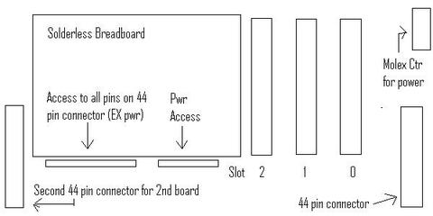
Heres what the board might look like.

Adding a solderless breadboard to it, although a space hog, can help in the creation of other cards (sorta like a Board of Education that parallax makes), so prototypeing could be eaiser to do. And the second 44 pin connector can help in adding another slot board, or something else as well.
The spacing on the apple 1 slots appear to be .156" but I can't confirm that because I don't have one in front of me to measure. I've been going off of hires photos to estimate the spacing but most people believe .156" is correct. Now the spacing between rows I have at .2" because the sockets I found "not on digikey" shows .2" although the part # you pointed out appears to be more correct. The hole size is .035" as the sockets I was looking at had .029" size. I like the idea of a breadboard area because it's easy to do small projects with breadboard, although larger project require soldered or wirewrap boards even though the first version of the replica 1 I got working was breadboard
If the breadboard is a space hog, why not a connector so the user can decide to attach one if wanted. Remember the expansion connector on the replica is 40 pin (identical to IDE hard drives) and the 4 signals dropped were, 2nd gnd, DMA, VMA was also only for the 6800 and RF for DRAM refresh (I used static ram as it was cheaper).
I haven't ordered the expansion board and it is definately up for revision. If you are going to order a run of boards, let me know but more people need to be interested in order to validate a batch.
replica 1 The Apple 1 replica
http://www.applefritter.com/apple1/members/replica1/index.htm
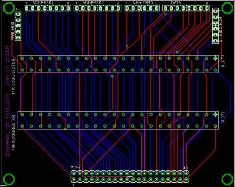
I finshed, the board, its like yours, but I opted out of a 3rd slot and added female headers so a breadboard can be hooked up on the side, I'll submit my cad files and a picture of the finshed board later tonight.
Ok I uploaded an image of the layout, feel free to give some input, now I just need to find a boardhouse to produce a prototype for cheap, then I can see if it works.

For some resason I cant seem to put shortcuts to the files I uploaded on this post, but I'll make them accessible on my website in a coupple days.
I had to redesign the pinout on the 40 pin idc connector, everything else is pretty much the same, ill post a follow up later today.