I recently picked up a IIgs System saver. I opened it up to see what it looked like on the inside and found that there are two resistors that seem to be running at too high of a wattage. They not only left burn marks on both sides of the PCB, but there is also a slight discoloring above them on the lid as well.

The heat damage also caused the pad to lift off the PCB when I took the resistor out to check it. These two resistors allow the LEDs to run directly off the mains. There are two LEDs in each switch, it looks like they installed them so they are also acting as a rectifier to generate the DC needed for the LEDs.
These resistors are dropping a lot of voltage. I measured somewhere in the neighborhood of 117vac across it. My mains are usually right around 120/121vac. The resistor colors are kind of hard to read, because I think the heat discolored them slightly. The resistors measured 7k ohms, but I suspect they are actually 6.8k ohms. Running that through Ohms Law, these resistors are dissipating around 2/2.1 watts. I can't say for sure if these are 2 or 3 watt resistors based on visuals alone. I sort of suspect these are 2w though. So I could put in a 3w metal film. But I think I may put in a 5w wire wound to give some more headroom.
Curious if by chance anyone else has opened up theirs, and noticed anything similar. And to maybe act as a warning to anyone else who has one that they may want to check. I mean, this thing hasn't started on fire in 30 some years. But still, better safe than sorry. This seems to be a poor design pushing parts to their limits.
I created an actual schematic of whats in there, if anyone is really curious. It's nothing too exciting. Just your standard EMI/RFI filter on the incoming power (inductor and a .47uF X2 safety cap across line/neutral), followed by 3 MOVs for surge protection (L-N, L-G, N-G), then the switches, resistors, and LEDs.
I don't have one to check, but are you sure there are LED's in the switch. This is no way to run LEDs off the mains voltage. A resistor cannot act as a rectifier. And no LED would withstand the 200V reverse voltage. So from what I see, it's probably just incandescent lamps in there. But your calculations would still be accurate and from the looks of it it does need a higher wattage part and should be mounted at least a half inch off the circuit board. As long as that doesn't put it even closer to the lid.
They are very much diodes. :)
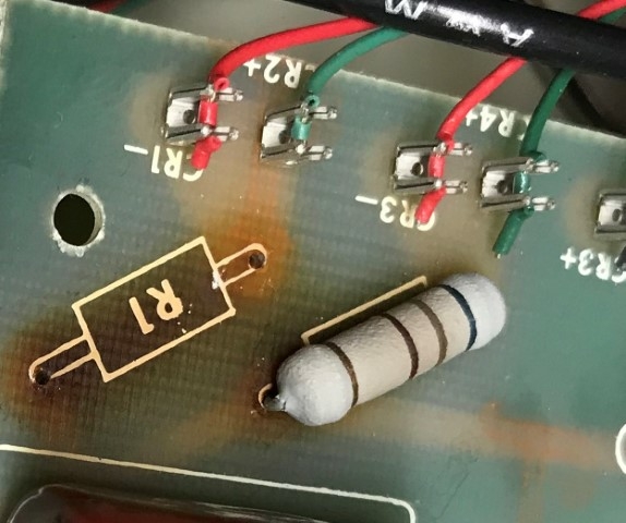
Sys Saver LED (Small).jpg
I didn't say the the resistor was acting like a rectifier. Each LED is wired up so that it is protecting the other. In the picture above, its hard to see as the wires go off the picture. But the brown wire is wired up to the anode on the top LED, and the black wire the cathode on the bottom LED. Both those wires loop around to the switched end of the mains line on the switch. The red and green wires then go off to the resistor connected to the mains neutral. The resistor is just just dropping a large amount of voltage.
I've attached the schematic I made. I've made every attempt to make sure its as accurate as possible, but I may have made a mistake. Its not pretty, but I never used KiCAD before. And coming from using a lot of Visio for making diagrams, its not nearly as friendly when moving parts and things around. Unless I'm missing something in the program. Also, before when I said there was an inductor on each line, I should have said there is a choke. I corrected it in this version. And ignore the +/- on the fan. I couldn't seem to find an AC fan in the library, so I had to use a DC fan. But the fan is a 115vac fan.
Ah. That makes sense then.
I just finished repairing a System Saver IIgs. It had nearly identical scorch marks. I used 5W resistors, and placed them 1/4" off the board to mitigate. I also replaced the safety capacitor and varistors while in there.