Hello,
I hope this exact problem was not discussed before. I tried the search function, but I am not able to limit the results to the Apple II forum.
I have a relatively good working Apple II: boots, loads software and games. However the video signal is bad, there is a lot of noise in the signal.
I am able to get picture on my monitor, but it is noisy (obviously) and has a bad contrast ratio between black an white.
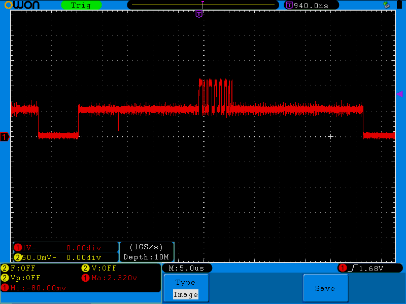
I tried to diagnose the problem and attached an oscilloscope to the internal aux video connector:
On the left the sync level is visible, followed by a lot of black and the APPLE II text.
As you can see, the noise level is significant high. And there is a short glitch down to almost sync level between real sync pluse and the text.
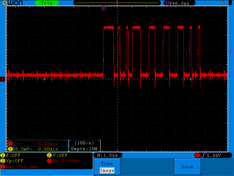
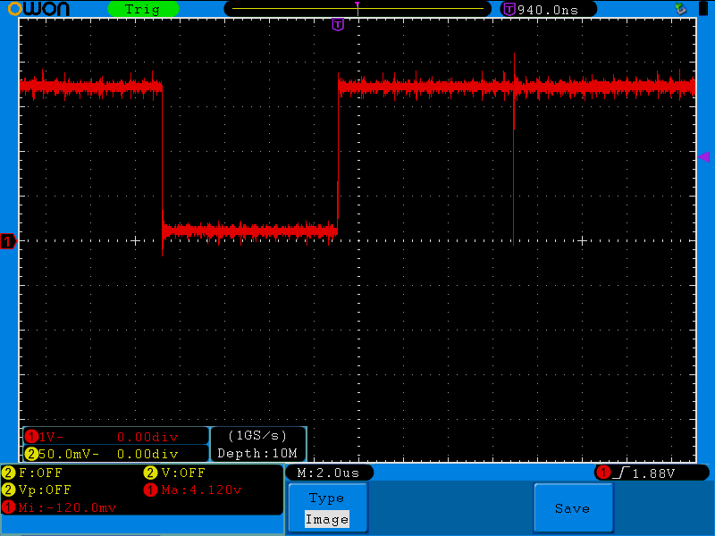
I recorded the video-signal and the sync-signal as well (the color burst signal is inactive and almost noise free, therefore I skipped it).
I think most of the noise is introduced by this signal. The high level seems a bit low (3.6v).
The sync signal shows less noise and has a better high level of 4.1v. However the sync glitch is clearly visible.
Does somebody have an idea what might cause the noisy video signal. I traced the sync glitch a few years ago and I temporarily fixed it by adding a delay. However, this did not improve the picture quality.
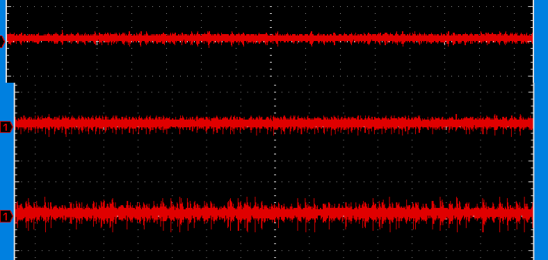
During my invesitgation I probed the ground level at different places of the board (top-bottom, near to far away):
The more distance between the probe ground and the probe, the more noise is visible.
I thought that it might be a problem of measuring high frequency signals over long distances.
However, the noise pattern resembles the pattern in the other signals and the video output.
Does somebody have an idea how I should proceed from here? Has somebody reference mesurements to compare to?
With regards
berni79


I forgot to mention, I am using a ATX power supply and the voltages lock good (measured close to the conntector).
I was wondering, if the ceramic caps on the mainboard could be faulty?
Replacing these would be difficult, because of the weak traces of this old mainboard. Is there any way to know without replacing them all.
I am grateful for every hint or opinion.
With regards
berni79
Silly question: Have you tweaked the video signal with the onboard video trimpots? (assuming it's a clone of the II+, they're usually up the left hand side above the video out port)
Also, just to eliminate it, what's the picture like with no cards installed? (Mine is much worse with the FDC card in)
From where I'm looking, those signal lines are no more noisy than I'd be expecting.
Cheers!
Chesh
Hi Chesh,
thank you for your reply.
I tweaked the video signal before, like you already guessed. However, this affects mainly the brightness of the picture.
The contrast won't execeed a certain level (e.g. I may choose between white cursor on gray ground or gray cursor on dark gray background).
The oscilloskope was attached to the auxilary video port. The video gain trimpot does not influence this port, as far as I undestand.
I thought this simplifies the comparision to other Apple II systems.
Sadly, I did all the tests without any additional cards... Maybe I should remove the optional ram chips as well.
Wtih regards
berni
As you observed in your last picture, the noise level will definitely depend upon how short your probe ground lead is and where it is attached. But since you can see the noise in the picture I would guess that there really is excessive noise in the composite signal. Just to be sure however, use a high quality video cable between the computer and monitor (not just some ordinary audio cable). And check the signal at the RCA jack, since there is a LP filter on there that is not present on the AUX video connector.
I would then start tracing the video output back through Q3, IC B2, IC A3, etc. I wouldn't worry about the glitch at this point and depending on your ground connection in the original pictures this does not look all that bad.
Before you go overboard: What are you using as a display, and do you know the specifics on the clone itself?
If you are using a CRT display and cannot adjust it to clear this, then it may be a transistor + cap on the mainboard failing. Some designs use caps to filtrate out noise and smooth the signal. You'd usually see a small cap with a 75 ohm resistor and a transistor to boost the signal in these sorts of video amp designs. Further, if the traces are too close to the earth plane, or the voltage rails, you can get noise from any of those. (This can also occur if the PSU itself is noisy and is sending that noise down its eatch path.)
Hi Jeffmazur,
thank you for your response. I use a very good cable and did the measurement at the RCA jack. However, signal quality at jack and aux pin is approximately equal.
I checked the video signal, but could not find anything but signal degredation caused by long traces.
The video signal looks fine if I measure the signal at B2 directly. However, the same signal looks very noisy, if I measure at R7 (using ground close to R7).
The noise is visible after Q3 as well, therefore I consider it to be "real". From there the noise is propagated to the RCA jack.
I will try to regenerate VIDEO-DATA and SYNC signals using a TTL-IC close to the resistors and Q3 (a short test looked promising).
However, this is only a workaround and I really want to find the cause of the problem.
With regards
berni
Hi Timelord,
thank you for your reply.
I tried several signal converters which translate composite to vga or HDMI (one Extron which normally does an excelent job). Aditionally I tried with a TFT -TV with composite input.
I know that a normal CRT would give better results, but I think the current picture quality is far worse than what is actually possible.
I will look for the filter cap and take some pictures of the board, which might help identify the clone.
With regards
berni
Which side of R7? The end connected to B2 pin 11? If so, then perhaps a bad trace? If not, then the noise must be coming from the sync or color burst gates. Also check the +5 at the collector of Q3.
Would you be able to share a picture of the the actual video output on your monitor?
berni
Please, please, try any CRT first. It can easily be an issue with your conversion box.
Hi Timelord,
I would try a CRT, but I don't have one.
The reason for the investigation is not the picture quality itself. I experimented successfully with a simple circuit, which uses TTL sync and TTL video to display a nice BW picture.
I am worried that there might be a fault that someday destroys the Apple for good.
In other words, I am happy, if somebody tells me that these measured video signals are normal for a Apple II.
With regards
berni 79
Are you in a PAL or an NTSC region? The Apple II Pseduo-PAL spec is something that a lot of decoders or upscalers will have trouble reading, in my experience. If it is trying to output a signal compatible with PAL CRTs, it is going to cause a lot of issues as the signal is not 100% PAL compliant.
Something went wrong, please see post below...
Hi Tony359,
this is how the video signal looks on my TV.
20201121_211702.jpg
The image actually looks worse in person.
The sync glitch is clearly visible. It is the vertical black line, the only part of the image which reaches actual black levels.
This is the reason why I temporaily fixed this glitch a while ago. However, this removed only the vertical line and did not affect the overall black level of the picture. Therefore, I did not make it a permanent fix.
Here is a short video, which shows the noisyness better than the picture:
VID_20201121_211830.mp4
With regards
berni79
Hi Timelord,
PAL or NTSC both give the same result. First the computer was configured as NTSC, then I changed it to PAL (replaced oscillator and changed jumpers).
I wanted to try PAL and a PAL color card, because I throught my video converters might have less problems with PAL (since I live in Europe).
However, the PAL color card does not work at all and the black and white image (without color card), just looks like the NTSC image.
Therfore, I will change the computer back to NTSC.
With regards
berni79
The line seems to be where the picture should end, right? The cursor should be at the leftmost end of the screen. The picture is a bit wobbly but to be honest I do not think the one generated by my Apple //e on an LCD monitor is any better? Particularly when the output is set to colour.
I'm not sure why your black level is incorrect. My Apple //e PAL version has two potentiometers which change the red/blue content of black. Not sure if yours have such control?
That line is normal. On a CRT is is outside the visible image on the overscan area.
Not outside the visible area. But negative going from black so it would normally not be seen if the monitor black level was wet correctly.
Just FYI, this is what my Apple II/II+ machines look like when attacked to an LCD- it just doesn't handle it and looks like crap. The pre-RFI boards may look worse than the RFI, but I think none look "good". It's just not anything close to a standard signal they are expecting to decode.
They are fine using old CRT displays.
Have you tried turning down the brightness? From your video it is obviously set way too high. If you turn it down until the glitch line disappears, most of the other noise will go away as well. If you cannot get it low enough, it might be that the glitch is interfering with the DC restorer or black clamp in the monitor. In that case, you'd have to eliminate the glitch first.
I agree. People are better off using a late 90s CRT television with A/V in, than this mess of a conversion.
I do not understand why people are having so much trouble finding a basic monochrome or colour CRT composite monitor. I used to be able to get them for free, or £1. IMO, aside from the original Apple monitors, that nicely match the design language of the systems, the best monitors to use are the Commodore 1084 series (you can also use 1702 and similar), as these have three modes available immediately, and they have a speaker (stereo with 1084S).
In fact, the 1084 was my suggested/advised benchwork monitor, as it worked with pretty much every system made prior to 1995.
Magnavox monitors were also good for this.
One of the other issues with LCDs is that you will never be able to simulate phosphour ghosting, which is intentionally used in some games. My personal favorite is the Monitor ///, as it has a very long persistence, although for most text things I prefer amber displays.
In general, LCDs are not a good stand-in. There is no 'true black' level on them, only a very dark grey, as they are bacxklit.
Plasma screens OTOH, are fantastic, but sadly hard to find these days.
P.S. That line does fall in the overscan of properly calibrated displays. You should adjust the H width so that it is offscreen, and so that the ] or > is visible.
Well, my Apple //e looks much better than that on my LCD but I agree that you cannot expect the intended quality on an LCD. It's hit an miss I think. On mine for example I had to tweak the colours on the Apple to stop the picture from jumping: that gave the black background a slight bluish tint and the instability disappeared. Again, nothing wrong with my Apple //e, it's just that the signal out of it is not designed with an LCD in mind! The same signal on my Monochrome Apple display is incredibly sharp.
Precisely.
IMO, people who expect thiese systems to work with a modern display are both missing the joy of using the original displays, and fundamentally misunderstand analogue video, and conversion of analogue video.
It's sort of like substitutung almond milk for milk in a souffle. In some recipes, it might work, but in general, it won't.
I prefer Soya milk :)
Timelord, in my case it's a matter of space. If I want the Apple // usable all the time, I have to use an LCD. I would not have space for an Apple // and a big CRT monitor on top on my desk.
I decided to retry my fix for the glitch, just in case.
I thought that the decoder logic of the TV or the converter boxes may use the lowest recorded signal level above sync as black level. This would explain, why the picture is too bright.
The fix looks like this:
Applied glitch fix
The result looks like this:
Oscilloscope view sync without glitch
The TV image shows no trace of the glitch, but unfortunately the brightness does not change:
TV image without glitch
Now I am absolutely sure that the glitch does not change the brightness of the picture. Therefore, I reverted to stock configuration.
However, I thought I should share this experiment and result with everybody.
With regards
berni79
Hi Jeffmazur,
I tried this before and the result is quite bad.
I have to turn the brightness almost to zero and the text looks very dark.
In the images above the brightness is about 50%. This setting works for all my other devices (e.g. CGA composite).
With regards
berni79
Hi Timelord,
it is not that I can't find a monitor. Prices on eBay are currently about 100 Euros for a 1084s, not great, but I could afford one.
For me it is more a question of storage space and my wife's tolerance for more old "crap". I understand her point of view: For someone who is not into old computers this is just more useless stuff.
Therefore, I avoided buying a monitor until now.
With regards
berni79
I guess if you come up with a way to process/filter the video so that an LCD will decode the contrast/levels properly, that would be a great thing. My guess is it somehow activates the AGC (automatic gain control) in the composite input circuit on the LCD.
You could probably even make a kit and sell them...
With the brightness down and the contrast up can you get a decent display? Also as a test, you could try running the video through an old VCR if you have one (Video In to Video Out).
That's still require having something that can accept the analogue tuner output... Unless you are using a television that was made before around 1995, most have RCA composite video in, and many accept both NTSC and PAL.
One thing that may help, is to put a small cap of around 1uF tied to a 75Ohm resistor on the video signal before it goes into your decoder.
->Signal->1uF->75Ohm->Decoder
I fully appreciate workbench space limitations. I have a Monitor //c on my bench now because all of my rework tools eat up so much space. I need to expand my work area, as it is getting too cramped to work on larger boards. There is some furniture moving to happen in the future.
Not sure what you mean here. Not suggesting using either the RF "tuner" in or out. Just composite video.
Still think this would be a good test to see what's happening.
Hi Everybody,
today I have great news.
I was browsing through the "Apple II Circuit Description" again, searching for clues. When I found the reference voltages for the composite video signal on page 39:Sync level 0V, black level 0.5V, white level 2.0V and burst levels +-0.7V peak to peak are specified there (no load, R11 at max).
Therefore, I did a quick measurement and the all voltages, but the black level voltage, matched perfectly. The black level was twice as high, 1V not 0.5V. I measured the resistors R6 to R8 and sure enough R8 was only 1K Ohm instead of the required 2K Ohm.
One quick hack later (I had no 2K resistor at hand):
2k resistor repair
Hello world test screen
This was the moment when I got greedy and tried to display color.
Sadly the color did not work. With some of my converter boxes and my LCD-TV I could see colors for a fraction of a second, sometimes. I concluded that this may be a crystal related problem. The oscillator part of the Apple was not in stock condition when I got it. The "original" crystal is low profile, which I think is odd for such an old machine.
I have read a lot lately about the Apple II color burst, crystals, serial and parallel resonance and so on. My guess is that someone swapped the crystal in the past and replaced it with one working with 14.318 Mhz parallel resonance. "Serial" 14.318 Mhz crystals seem very hard to get in Europe and I am an impatient guy. Therefore, I decided to "hack" through the problem.
I used an Atmel MCU which has the ability clock from an external "parallel" crystal and output the clock at one of the pins. The MCU together with two capacitors and the "original" crystal constitute one crude clock generator.
This is the resulting circuit:
Clock generator
And these are the resulting images:
Apple II color test boxes
flight sim color
I am as happy as I can be. My thanks to everyone.
With regards
berni79
P.S. The color images look better on my TV. Not perfect, but I think this good enough for a TFT.
I am not shocked by the peak voltage issue. My earlier suggesstion was based on a solution where I had encountered that type of issue in the past, but on a normal CRT, where the image was desaturated due to too high of a line voltage.
That red looks wrong: Should be orange, but the colour burst technology probably does not decode well.
Hi,
does somebody know the value of the L7 inductor? I want to add RFI video output filter to my board.
With regards
berni79
@bernie79:
"The black level was twice as high, 1V not 0.5V. I measured the resistors R6 to R8 and sure enough R8 was only 1K Ohm instead of the required 2K Ohm."
As you may known... old carbon film resistor values can vary, because of their age. They are often losing their value, somtimes down to 0 Ohm. I just had such an example with a Commodore plus/4 computer. A 1 MOhm resistor had 0 Ohm now and there was no physical damage seen. So it's almost a good idea to check carbon film resistors if they are still in spec.
This may be the case, but the other resistors were all correct. And the sync resistor was exactly 1k.
But who knows... I am just happy I found the problem.
With regards
berni79
Great job tracking that down and fixing it. Enjoy!
Well done!!
Back to when someone was trying to adjust the black level using "brightness": most monitors/TV indeed work like that, that is, "brightness" adjusts the black level of the signal. On other devices the brightness controll adjusts the backlight instead...