So, i'm in the middle of restoring a recent eBay purchase, a very low serial number Bell & Howell Apple II. The unit is remarkably unscathed after 43 years, with a case in near perfect condition. The hardware inside is all Apple-manufactured. There's just one problem. The video is out of sync..and I dont know enough about how video works to fix it, or even explain what's going on.
What I _do_ know is that there are two adjustable potentiometers inside the case near slot 7. One adjusts the black level, and one is labelled "color trim". Both the black level and the color trim can be adjusted nicely, but, the frame of the image itself is slanted diagonally, and seems to drift both horizontally, and vertically, slowly.. Here's a video or two explaining what i'm talking about:
Video problem vid #1 (I power off/on the unit a few times over the course of this video)
Video problem vid #2 (I power on the unit, and power it off)
For what its worth, the definition of the text itself seems fine. Each letter is well-defined, clear, and crisp...its just the sync timing of the image itself that's all jacked up. Where do I begin to diagnose this? I have a spare Apple II+ that I can pull parts from...can this be solved with a simple chip replacement?
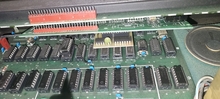
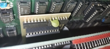
The only other thing I can think to mention is this -- I recently had a peek inside, and discovered there's some sort of daughterboard plugged into an area (or near an area) i've read is associated with producing the video signal. Does anyone happen to recognize what this might be?
Any light anyone might be able to shed would be greatly appreciated..I'm new to Apple II hardware diagnostics, and doing my best to do my homework, here, but i'm at my limit of understanding. :(
It looks like that daughter board is plugged into the character rom socket. And it also is hijacking some signals off of B9. I'm pretty sure B9 is used for graphics, and the character rom is for text. Neither should cause rolling pictures AFAIK. But I honestly don't know much about pre-IIe/c hardware.
It might be helpful to someone else to identify the board if you take the top of the case off and get a clearer picture of the daughter board, and what ICs are on it.
That's my next step.
For what it's worth, I contacted the eBay seller and asked him/her about it. They replied that they had recieved it second-hand from a former Bell & Howell Employee (!), an engineer. This explains a few things...1) the ridiculously low serial number, and 2) the lack of any serial number etched into the case as you would typically see from an educational sale, and 3) the lack of any secondary Bell & Howell stickers on the case that would have been applied if this system was destined for retail sale, the weird (48K) stamp on the badge.. This one only has an Apple sticker..no Bell & Howell sticker on the belly whatsoever, even though its a Bell & Howell (A2S3) machine.
The unit shipped with a rather strange looking card. Made from an Apple prototyping board, it has a single flip-flop chip and a toggle switch on it. If you flip it up and down once, it breaks the system out to a debugger, allowing you to examine memory contents and such. The daughterboard, i'm thinking, is also the work of this same nameless engineer...the plot thickens.. :)
Aha! Solved it!
This daughterboard is an "Enhanceware LCA-1" lower case character ROM hack... thank you Google...
(1982) Apple II - Dan Paymar - Lower Case - LCA-1 | #1903399956 (worthpoint.com)
So that leaves us with the main mystery...what the hell is causing the vertical/horizontal drift in the video signal?
I would take out all ICs (gently) and make sure there are no corrosion on the legs. That can easily happen over the years.
Clean the legs and reseat them in the sockets.
Optionally use just a drop of Contact Cleaner in the sockets.
See if that makes any difference.
... everything else seems to work OK.
My old Apple II schematics which came with all the early machines tells me that SYNC is generated by the 74LS51 at location C-13.
My money is on that IC being bad. Or has a bad contact. If you have an oscilloscope probe pin #8 of this IC. If you see proper SYNC pulses there the 2k summing resistor R8 is bad. Which should be near the 2N3904 connected to the video output.
If you see a SYNC signal then you can also try to crank up the 200 Ohm video trimmer R11, but I don't think this is the culprit.
- Uncle Bernie
So a few years back I added a lower case apple II chip to my plus. It works pretty well. But a few programs. Like apple writer original. Does not print the correct correctors on a few keys. Even
when I hit the space bar It prints an closed apple symbol. I tried anohter lower case chip. Same issue. The chip works fine on Applewritter II. So I'm thinking with that board being able to support both lower cae and the uppper case rom with some kind of switch. That would solve the few programs it caused issues with.
TTTFN,
Josh
Closed Apple symbol on a ][+???
That character shouldn't be in any normal ][+ CHARGEN image. That symbol normally only exists in the //c or Enhanced //e image. ][+ normally also uses a 2716 (2Kx8) vs the 2732 (4Kx8) size EPROM for lower case.
I'd burn another 2716 with a known good LC CHARGEN image. I've got one I've used for years (like since 1981 or so). I don't know where it originated exactly, a friend of mine who had a Mountain Hardware ROMWriter back then burned the original for me and I've copied it every since. I'm pretty sure it isn't exactly the same as the common Dan Paymar chips, but it works great with anything I've tried for a ][+ that worked with lower case.
If you really want to get a visual dump of CHARGEN images, you might try the utility I wrote, chargen2png:
https://github.com/softwarejanitor/chargen2png
https://github.com/softwarejanitor/chargen2png
So I spent the evening prying and plugging, swapping out chips with ones from a working system....and no luck.
I am officially stuck.
Does anyone have any information on specifically which ICs are involved in horizontal and vertical video sync / blanking generation, and where they are located?
I also did one of these. :)
Browser script to decode Apple II char ROMs. Just select the ROM file and the browser converts it to an image locally:
https://thorstenbr.github.io/Apple_II/html/apple2_video_rom_decoder.html (Source).
Mine is a desktp GUI app in 316 lines of Perl GTK code. It wouldn't be too hard to take the inner logic and make it into a web app.
As the logic chips in II+ tended to be fussy, I recall there were a number of troubleshooting books published. A+ did a 3 part series on troubleshooting and repairing the II+, as did others like SAMS. If you search the PDF below for the word "sync", eventually you'll get to page 90 in the PDF (88 in the PDF reader) of a section that troubleshoots horizontal sync. There it tells you to check/replace the aforementioned C13, along with C14, D13, and D14. The section right before horizontal sync issues for vertical sync issues also includes checking/replacing D11 and D12.
https://vintageapple.org/apple_ii/pdf/Apple_II_Plus_IIe_Troubleshooting_&_Repair_Guide_1984.pdf
Also keep in mind the IC may not be bad, there could always be some corrosion in the socket. Hopefully pulling and inserting a different IC would scrape away the corrosion in the socket, but that may not always be the case.
In post #10, bus_error wrote:
"Does anyone have any information on specifically which ICs are involved in horizontal and vertical video sync / blanking generation, and where they are located ?"
Uncle Bernie answers:
In the early Apple II these TTLs were involved in the SYNC generation:
74LS02 at B-14
74LS02 at A-12
74LS04 at C-11
74LS08 at B-11
74LS32 at C-14
74LS51 at C-13
The counters feeding this logic are the 74LS161 at: D-11, D-12, D-13 and D-14
But if these counters don't work the video most likely would be worse. There is a possibility that one (or more) of the signals from the counters to the SYNC logic gets stuck due to some bad IC socket contact on either end of the trace. I think without a schematic all you can do is to swap the above ICs against known good ones. With a schematic and proper instruments you could check the connectivity and with an oscilloscope you could see the signal(s) at the source and where they are supposed to go to.
Also note that there are five 50Hz/60Hz cut and solder options in the machine and if somebody messed with these all bets are off.
And I don't know if your Apple II fits to the schematic I have. I don't think the extra card in it is the culprit. These character generator mods were quite common and they normally do not modify the video timing logic. They don't even are wired to it. They are sitting downstream of the video data path which can't have effects on the SYNC logic or video timing that is upstream of that.
- Uncle Bernie
So when you run a see what you charactor roms has. It shows those symbols. When I press the space bar in Applewriter. It does ' that for a symbol. Applewritter does the same thing when I used is on a emulator for a iie emulation. I did go out and purchase a 2nd lowercase rom chip. The first one was from an apple II+ vision 20 by VISTA. Anyway I did find vintage ads about it and it does say for my revision of mainboard and such. Now the strange part is the 2nd (reproduced) lower case rom showed the same charactor set and have the same issue. It in another post some place in this forum. I did read that sometimes some of the mfg would just copy the iie charactor set. Sometimes I wish I could go back in time.
Oh and one more thing. Not that this is really related. I have a Applied engineering viewmaster 80 card and it hates apple writter II even thuogh all the add say that should work with it. What happens if the software kicks the screen into 80 columns and goes blank. Oh and the 80 column card works just fine any place else.
TTFN,
Josh
Slight update. I put the rom into that reader and it shows what is outputs on the II+ basic I run. But I found a lowercase rom on a site for a II+. It is different. Does not have those symbols.
If that is the case. I'm supprised the person on ebay is selling the one I have and not the other one. Going to look for anohter few images.
Great news!
I'm hoping with this post that I might be of some use to somebody in the future, to leave some bread crumbs.. I found a solution to my Bell & Howell Apple II's video sync issues.
Get a different TV.
It's literally that simple.
I hooked up my Apple II to a small, black and white CRT CCTV monitor, aaaaand, suddenly, it works perfectly. Crisp and sharp as it can be. I learned along the way that the Apple II puts out a composite signal that's too "lazy" and unrefined for modern TVs and flat panel displays to correctly adapt to.. As someone else (possibly in this thread, or elsewhere) pointed out, the composite signal on an Apple II is only a loose interpretation of the specification.. this was apparently fine back in the 70's, as most displays had controls for sync adjustment on the TV itself. My early 90's TV was basically turning its nose up at it.
I'd like to say thanks to everyone who chimed in on this thread, and offered me a ton of places on the motherboard to look at. I tried them all. It was actually fun (frustrating, but fun) to learn how about how this stuff works. Here's a nice victory photo:
V_LEbn1ETm2VrypMwgpoNA.jpg
Thank you!
While the A2 composite signal is a bit off spec, I wouldn't lump all new/modern TVs into the category of not working with them. I have a 3 year old Samsung QLED that plays quite well with my A2 machines.
But with everything in life, YMMV.
There's actually another little added wrinkle to this story...
I just found out that the person who sold this system on eBay also decided to break up the system thinking they could get more money for it (UUUGHH!! WHY?? WHY are you doing this?!).. This included the nice redbook the original owner had made some notes in.
One of those notes is a little mysterious..
My question is --- Why would someone cut out R18 and replace it with an 820 Ohm capacitor? Maybe that had something to do with my video issues?
manual.png
Resistor, resistor... He changed R18 with a 820 Ohm _resistor_. So, he just adapted the value.
R18 would normally be a 100 Ohm resistor of the output voltage divider for the "cassette out" signal. If the numbering was the same for the B&H Apple II, then he just adapted the signal level of the cassette out signal - which is completely unrelated to the video output. Maybe he was trying to better match the signal to his his tape recorder. Uncle Bernie would know... :-)
In post #19, MacFly wrote:
"Maybe he was trying to better match the signal to his his tape recorder. Uncle Bernie would know... :-)"
Uncle bernie comments:
Yes, Uncle Bernie knows. I never succeeded in making a good, reliable tape recording on my Apple IIe nor on my PC-48 clone (which I verified has exactly the same cassette interface circuitry as the early Apple II and II+, plain Taiwan Chinese copycats). I did not look what is in the Apple IIe TAPE OUT. In both machines I put a 4.7k ... 10k resistor in parallel with the 12k resistor R19. Which is part of the R19/R18 voltage divider. Original values 12k / 100 Ohm. This is where they made the Apple II worse than the Apple-1. The Apple-1 ACI has a 10k / 100 Ohm divider and the result is that the digital noise on TAPE OUT has a larger amplitude than the signal itself. And it's weak, I found that with many (but not all) cassette recorders I tried the recording to be dull and mushy. Which does not help with readback reliability. Double or triple the TAPE OUT signal amplitude by paralleling a suitable resistor to R19 and you get a much crisper recording on typical cassette recorders. You can, of course, change the R18 but this involves desoldering a component which requires a full disassembly of the machine. I wonder why anybody suggested or decided to take this riskier route. But it is as it is ... I would leave this mod alone as long as I could make good tape recordings.
Oh, and this is the first time I saw a good photo of a black Apple II. Are these the "Darth Vader" ones ? Or do you need some extra accessories like a light saber ? Sorry I did not follow the Apple II collector scene too much, so I don't qualify as a true Apple collector. I'm more in the really obscure early microcomputers. Ever heard of the LSI-11, the Fairchild Microflame, the Data General MicroNova, or the elusive National Semiconductors IMP-16 ? My focus as a collector is on those. Oh, I also have an IM6100. The PDP-8 on a chip. Most people in the vintage microcomputer scene never have heard of those. The mind boggling part is that these famous and powerful and wealthy minicomputer companies saw it coming ... their TTL based huge rack-filling minis with HDDs the size of a washing machine suddenly being shrunk to 1...5 chips for the CPU and the HDD shrinking to the size of half a shoe carton. And they did not see, or did not want to see, the consequences. They all went belly up a few years later. Witnessing the microcomputer revolution from the very beginning was fun. And I had a good run as a chip designer, too.
- Uncle Bernie