
Being retired a few years ago, I started repairing some of my Apple computers. Learning many things thanks to video uploaded by a couple of guys.
Being in USA for 5 years now, I realized that there was a huge source of vintage computers, most of them available for reasonable price. I have now more than 30 Apple computers (and a ZX81), most of them working and exchanging data on my internal network.
I decided a few weeks ago to look if I would be able to build an Apple 1.
I am facing some difficulties, but before talking about it, it might help to know. the most important steps that I made.
This is what I have been doing. Might help anybody who would like to start. Contact me if you would like more details.
Read many articles on this site (thanks all of you for helping each other), check some youtube video, and decided to go for it.
Start looking for components but then decided to buy as follow:
- Mainboard from Apple-1 Replica, Armin in Germany, with the PRoms. Arrived mid August
- Components, including transformers, from Unicorn Electronics. Arrived Aug 20.
Following mainly Mike Willegal build guide and a couple of videos:
- Tests of all passive components
- Decided to buy the 0.1 uF for the decoupling, instead of the 1 uF provided.
- Start soldering all passive components and the sockets, 1208 solders!!!
- Numerous checks to be sure that no bad solders
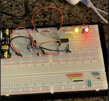
- Build the PSU early september, just using a temporary wood plate.
- Connect the PSU to the mainboard, All voltages where good.
- Had nothing to test the ICs, so I decided to populate video IC only.
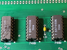
- First I thought that IC temperature was ok but as there was no video signal on small oscilloscope, I realize that tenparature of the D7 74161 was very high, actually 65°C.
- Start testing the 74161 with breadboard circuit (none of them are 74161A)
- All of them are not working, but present different lighting sequence
- Start checking the schematic diagram and found that the 2 IC 7400 are not working either.
- Start testing the 74161 with breadboard circuit (none of them are 74161A)
Being in VCFMW in CHicago last weekend, I had the opportunity to buy a Retro Chip Tester. Not cheap, but I wmet for it.
I can confirm that all 7xxx chips are ok.
I have ordered new 74161 and 7400 but I am concerned that the mainboard could be faulty/damaged so I start testing all connections around the 74161.
As you will see in attached document, everything seems ok except the red line at the top, connecting D7-8-9 74161 and D6 74160. Nothing is connected
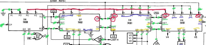
My questions so far:
- D7 74161 has 7.5 ohm between pin 16 (Vcc) and GND. Could this be the reason why all 74161 and 7400 are dead?
- I do not understand why there is no connection between D7-8-9 74161 and D6 74160. Could the board been damaged?
Thanks for your help
The first picture shows a dry solder joint at the capacitor.
It's not uncommon for circuit boards to get scratched, which breaks the continuity of the copper trace. When you tested connectivity, were you probing the holes on the board, or the chip pins, or the socket?
The date codes in 1973 for the SN74161 are a bit fishy. It's more common to find these chips with later date codes, although "collectors" preen about visually "correct" components made before 1977.
Thanks for your reply.
I am going to check all these solders and reflow them.
Connectivity tests have been made mainly on the sockets, but in case of lack of connectivity, I checked on the solder on the other side of the board.
So, that means that a dry solder joint at the socket could break continuity.
Sorry, there is a misunderstanding here.
I did check at the back of the board to be sure that I had the same result, which was the case.
I never had no continnuity on one side and continuity on the other.
But better to check again and correct any dry solder joint...
This schematics is a bit better: Redrawn Apple 1 circuit diagram (found on retro.HansOtten.nl) it's still not error free.
Here you find the Gerber files that are used for many of the PCBs https://www.applefritter.com/content/apple-1-replica-gerber-files you can use a gerber viewer to analyse the real connections easier in see through mode.
Found it here is a KiCAD Version of the schematics: https://github.com/baldengineer/bit-preserve/tree/main/Apple/Apple%20Iconverted the two main parts to a picture I can attach, hope that answers your question.
0f0521c9-a5e6-4f6a-8d67-d21ae80c8fd0_4.png
0f0521c9-a5e6-4f6a-8d67-d21ae80c8fd0_3.png
Please note this comment in the left upper corner on the picture of the terminal section.
The Apple 1 is not an example of bad PCB design.There floting inputs will for sure cause problems if you use LS or HCT types instead of 74 no letter number parts maybe even with the original parts.Some PCBs sold fix one or more of the desing flaws from the original design.