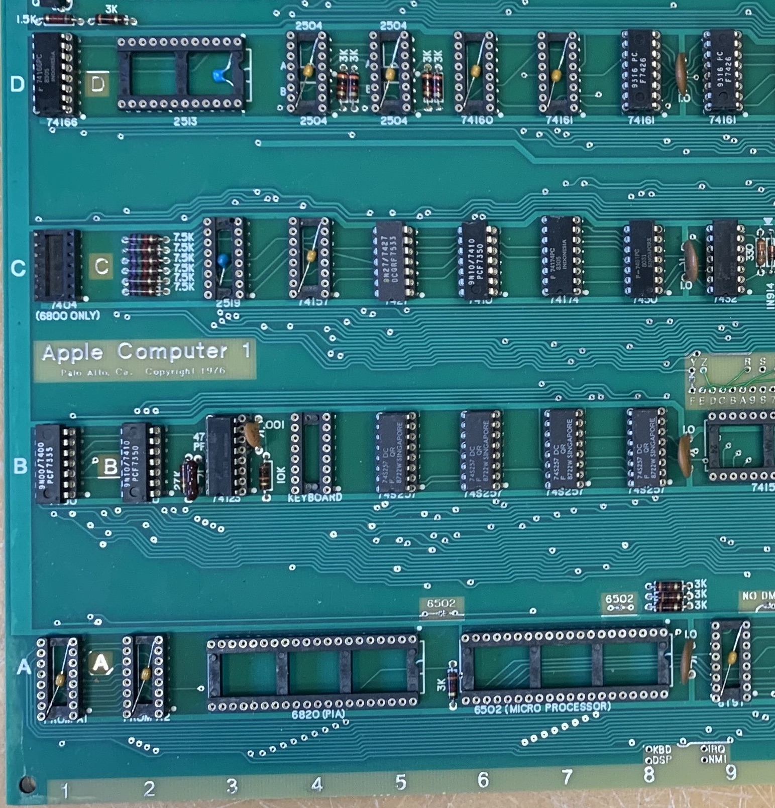
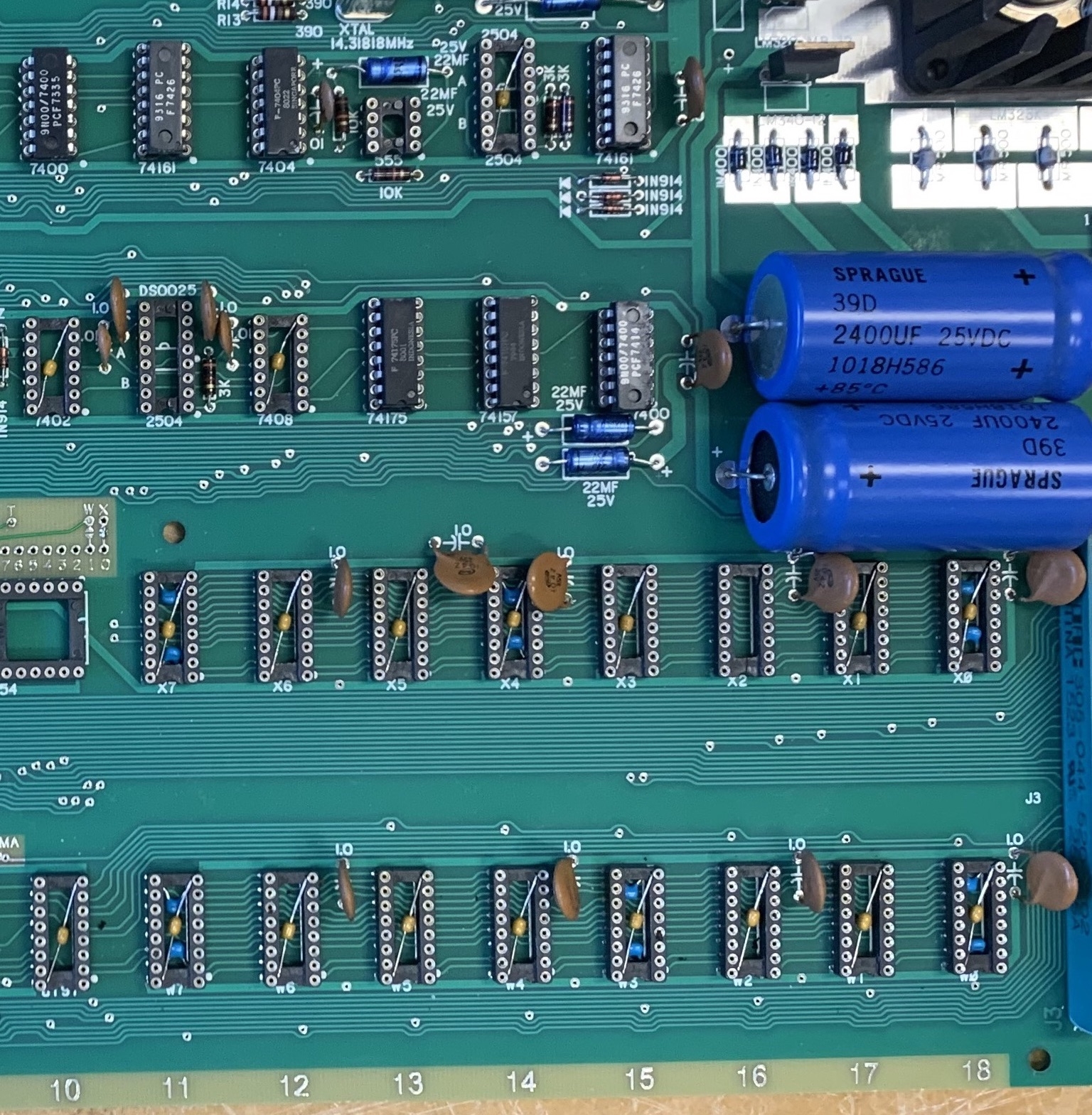
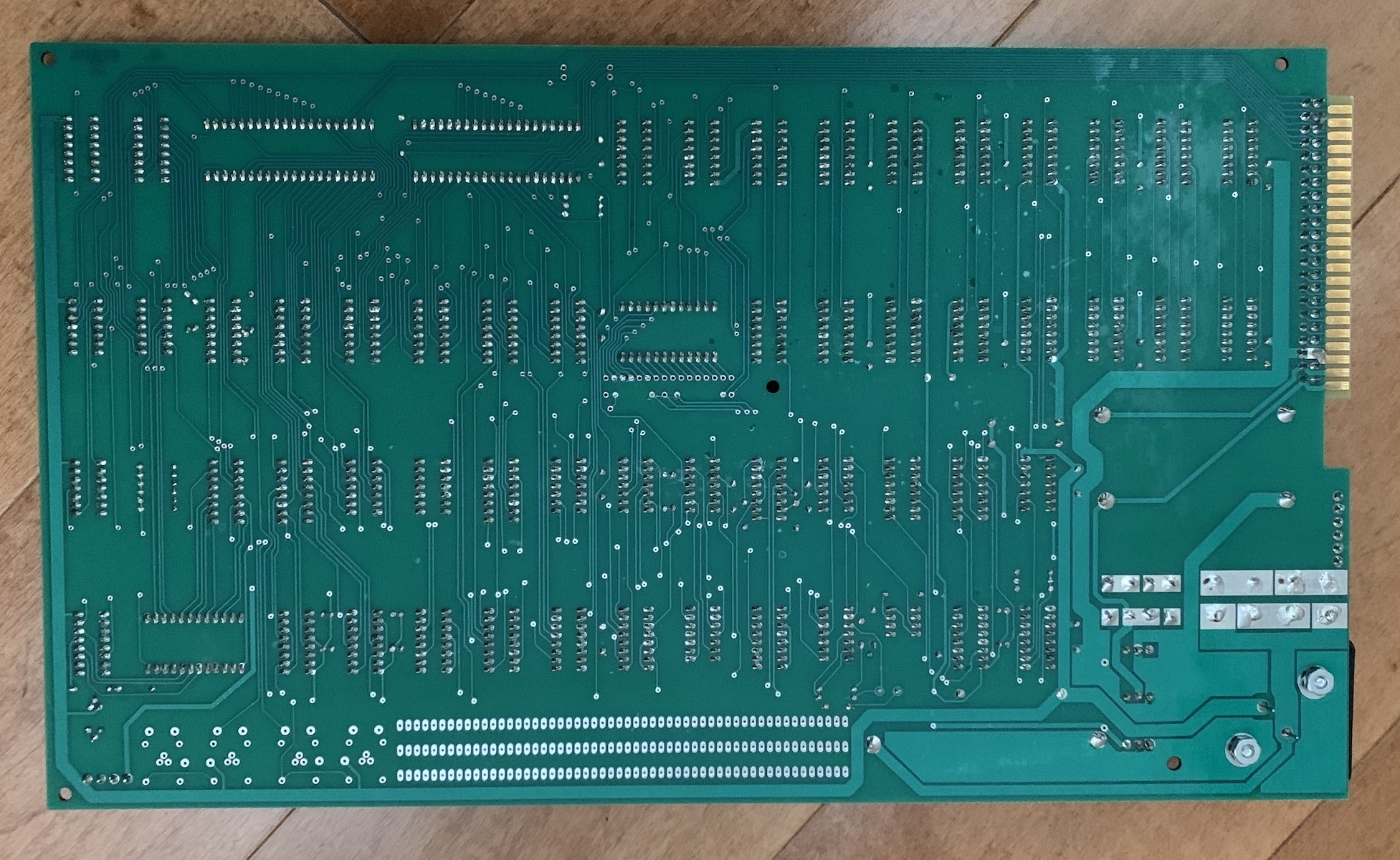
The Apple 1 (and Mimeos) has some noise problems that can be improved with additional filtering. Adding more capacitors helps the noise problems significantly but the downside is the visual impact. A solution is to bury the capacitors in the socket above the board but under the chip where they are not visible. You can buy sockets with the Capacitors installed from TTL Vcc to GND which is what I did for a couple of my boards. I also added a few more Capacitors under the sockets to help filter other supply voltages. As can be seen from the first two pictures when the ICs are inserted in the sockets the capacitors are not visible. From the last picture the capacitors are also not visible from the back side. The sockets with capacitors used are:
16 pin - Mil Max 110-93-316-41-801000 (001000 with no Capacitor)
14 pin - Mil Max 110-93-314-41-801000
Sockets with 0.1uF Cap are installed in all 14 and 16 pin locations except;
C1 - Empty
C3 - 2519
C11 - 2504 and DS0025 Combo
B4 - Keyboard
Capacitor Locations D4, D5, and D14 - 2504 will have Caps between -5V and +5V.
Locations B11, B12, B13, B14, B15, B16, B17, B18, A11, A12, A13, A14, A15, A16, A17, and A18 - MK4096 will have Caps between GND and +12V
All 34 other locations will have Caps between GND and +5V
Additional 0.1uF Caps are added as follows:
D2,3 2513, Cap between pins 1 (-12V) and 24 (+5V)
C3 - 2519, Cap between pins 5 (-12V) and 16 (+5V)
B11, B14, B18, A11, A15, A18-MK40906, Cap between pins 1 (-5V) and 16 (GND) and Cap between pins 8 (+12V) and 9 (+5V)
This adds 59 filter capacitors that are not visible but still does not completely eliminate noise problems. It is very hard to design good power and ground routing on large 2 sided TTL boards. The final fix would be a buried ground plane, that along with the capacitors should clean up the signals and would not have significant visual impact.
Great post. I will try to retrofit this to one of my spare Mimeo systems. If it works out well, I'll update the Mimeo at the VCF museum's unit since that one is used for entire weekends at a time.
Cheers,
Corey
Agree, this is a great post.
You did much the same as I did with my build (I also used lots of sockets with built-in caps) but the idea to hide the further extra caps in the sockets is new. Wish I had done that. Will use this trick in my 2nd next build which again will use machined sockets. My next build will aim at as-authentic-looks as possible and use the "boxy looking" sockets and these terrible carbon composite resistors. Ever measured them before and after soldering ... terrible drift. No good for the DRAM timing oneshot.
I'm quite sure that proper capacitive bypassing - especially on the -5V rail - will greatly improve the reliability of any Apple I.
I've posted my grievances and experiences on this forum several times in the past few months and after adding the massive -5V filter bank on all the DRAMs my Apple I build now runs perfectly 24/7 for months (mostly Mike Willegal's RAM test and my BASIC checksum test, too). Not one glitch ! Not one bit error ! And I tried all sorts of DRAMs, Motorola, Mostek, Intel, all of them finally work perfectly with no issues !
Here is my "final" state of bypassing which solved all my DRAM problems (see my comment of this thread):
https://www.applefritter.com/content/ready-start-building-my-pem
I ended up with 8 x 100nF capacitors on the -5V rails in the DRAM bank, 8x 100nF capacitors on the +12V rail in the DRAM bank, 2 x 100 nF on the +5V rail in the DRAM bank, and one 100nF capacitor at each -5V rail on each socket having the 8 pin shift registers.
The insidious thing with the current spikes not finding sufficient bypass capacitance is their elusive nature (hard to measure properly as there is no "solid ground" anywhere to be found on the Apple I PCB) and the fact that their position shifts around with temperature. If the supply voltage collapse caused by any spike just happens at the "right" time, the noise immunity of the DRAMs inner workings gets compromized and then a bit may flip (or not). Some brands of DRAMs appear to be more sensitive to this messy power supply than others. But after proper bypassing is added, all the problems disappear, regardless which DRAMs are used (as far as my testing goes).
Bernie