| Attachment | Size |
|---|---|
| 2.49 MB |
Hi all,
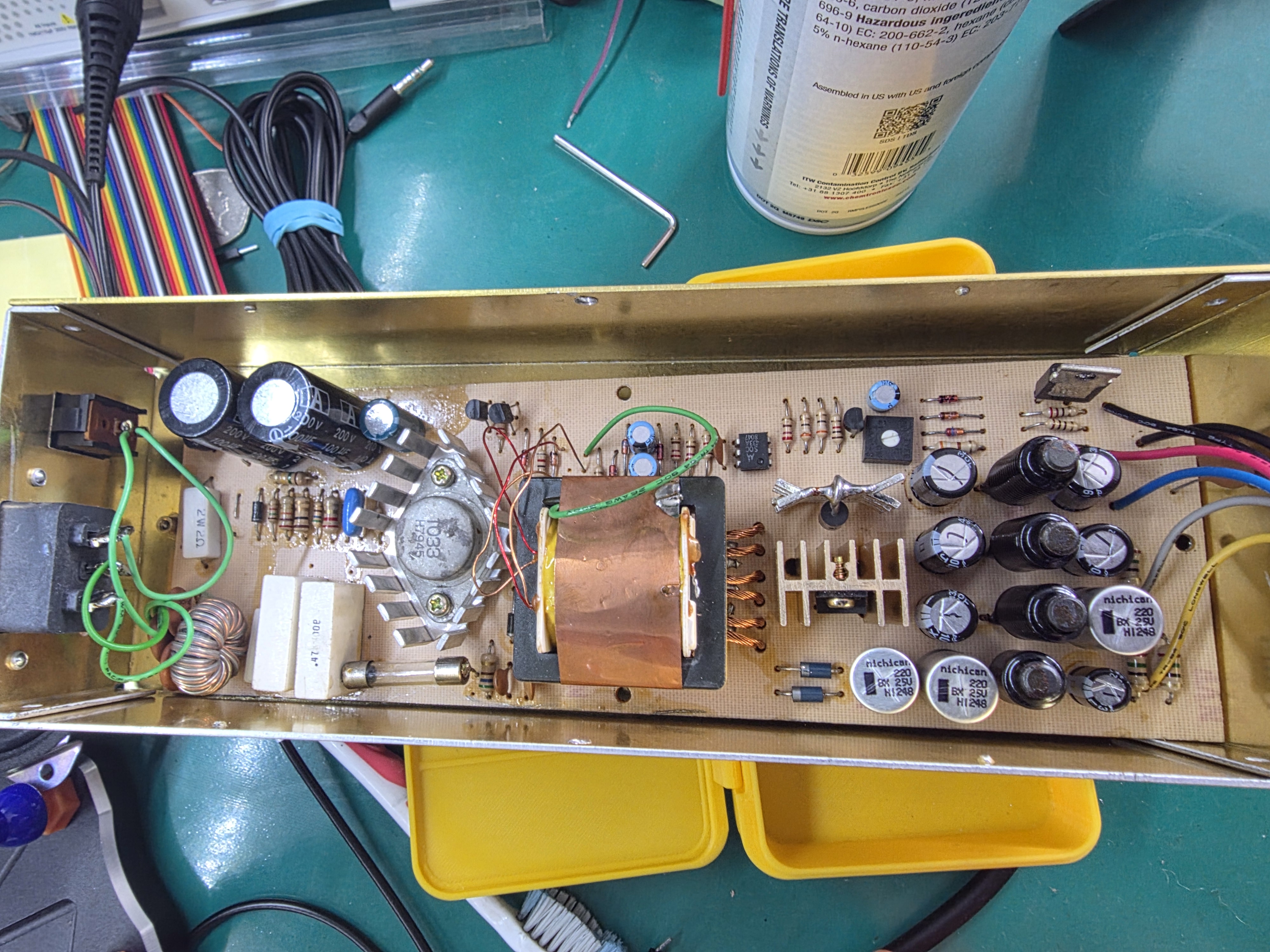
Does anyone have the schematic or a photo of the caps in a Leadman Apple II clone PSU? I'm replacing caps that someone else has removed and there's no silkscreen to indicate polarity. Just smelly-popped and 1000uF as I put it in the wrong way.
Photo of the PSU attached with new caps but wrong polarities!
Usually you can suss out the polarity, at least on the DC side, as all of the grounds are tied together. Set a multimeter to continuity mode and put one probe on a kown ground point (like one of the black wires), then probe each of the capacitor's pads. The pads that show continuity (a dead short) will be the negative side of the capacitors.
That is definitely not a valid approach, as the PSU supplies both positive and negative outputs. What would work better is to follow the output rails back from the motherboard connector and (referencing the schematic) ensure that the smoothing caps are connected on the proper side to those rails. For the primary side, the polarity of the bridge rectifier indicates the necessary direction of the reservoir caps.
Without a schematic, there is absolutely no hope of any repair (and that applies in general to every type of electronics). If you cannot find a schematic, the first required step is to draw one.
Tiktak -
Be aware that all filter electrolytics in switchmode power supplies are special types which were specifically designed for that application. You can't put in cheap AC rated electrolytics without risking overheating / explosions / fire hazards. It boils down to the ESR over frequency and the common electrolytic capacitors only specify it at 120 Hz (or so). For switchmode power supplies they must be able to sustain the high ripple currents at the switching frequency and its first few harmonics. If the ESR is too high at these frequencies, the capacitors may overheat and explode once the power supply has to deliver sufficient load currents. The pressure relief kerf on modern electrolytics helps to prevent total disaster but be aware that the high pressure steam blast (from toxic electrolyte) from a popped open kerf still can make you blind if it hits the eyes.
Specifying the right electrolytics for switchmode power supplies is better left to professionals who design switchmode power supplies for a living.
Be warned.
- Uncle Bernie
There's a current line of thinking that "recapping" a power supply somehow makes it better.
Very few ever believe me that there is a non-trivial chance that they'll make a power supply worse (and many have) by "recapping".
Indeed. In this case it was the caps (all the 1000uF reading between 120 and 400), but trying to find what the designed ESR etc was is not easy after 40 odd years and no schematic. So it's either best efforts, or I may just replace it with a Mean Well RQ-50B and be done. I'm a bit surprised that I can't find any info on the Leadman 224 Apple II clone though. Thought it might be a common one.
It looks like a close clone of the Astec AA11040. These power supplies work with relatively low currents, and the ESR requirements are not particularly strict. I think you could just put in Panasonic FC series and call it good (or equivalents from other companies: Nichicon PW, etc).
Many thanks. I'll look up the schematic and see what I can do. I've put a Mean Well RQ-50B in for now and it's working fine.
This is the way.
It will work perfectly well and will likely give years of trouble free service.