| Attachment | Size |
|---|---|
| 433.84 KB | |
| 406.42 KB | |
| 327.3 KB | |
| 483.46 KB | |
| 373.4 KB |
Hi,
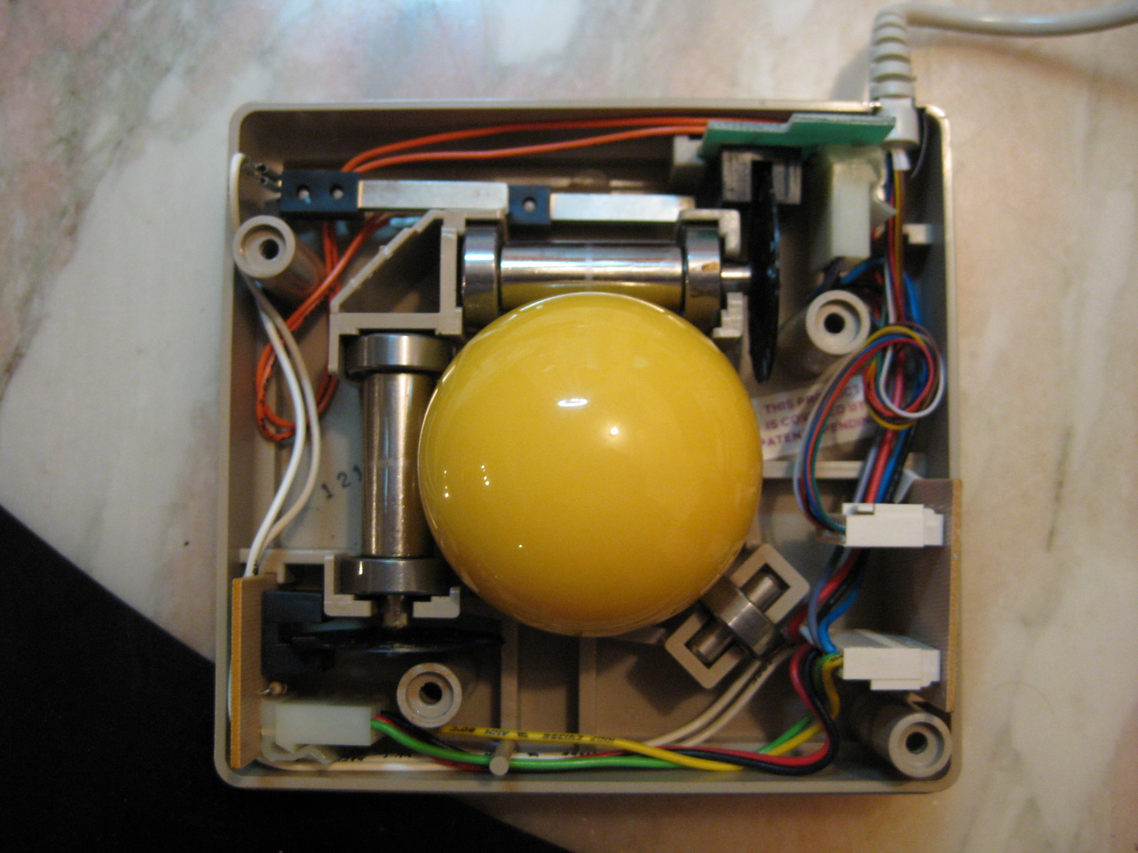
I'm trying to get a Wico trackball to work with my Mac512 with no luck.
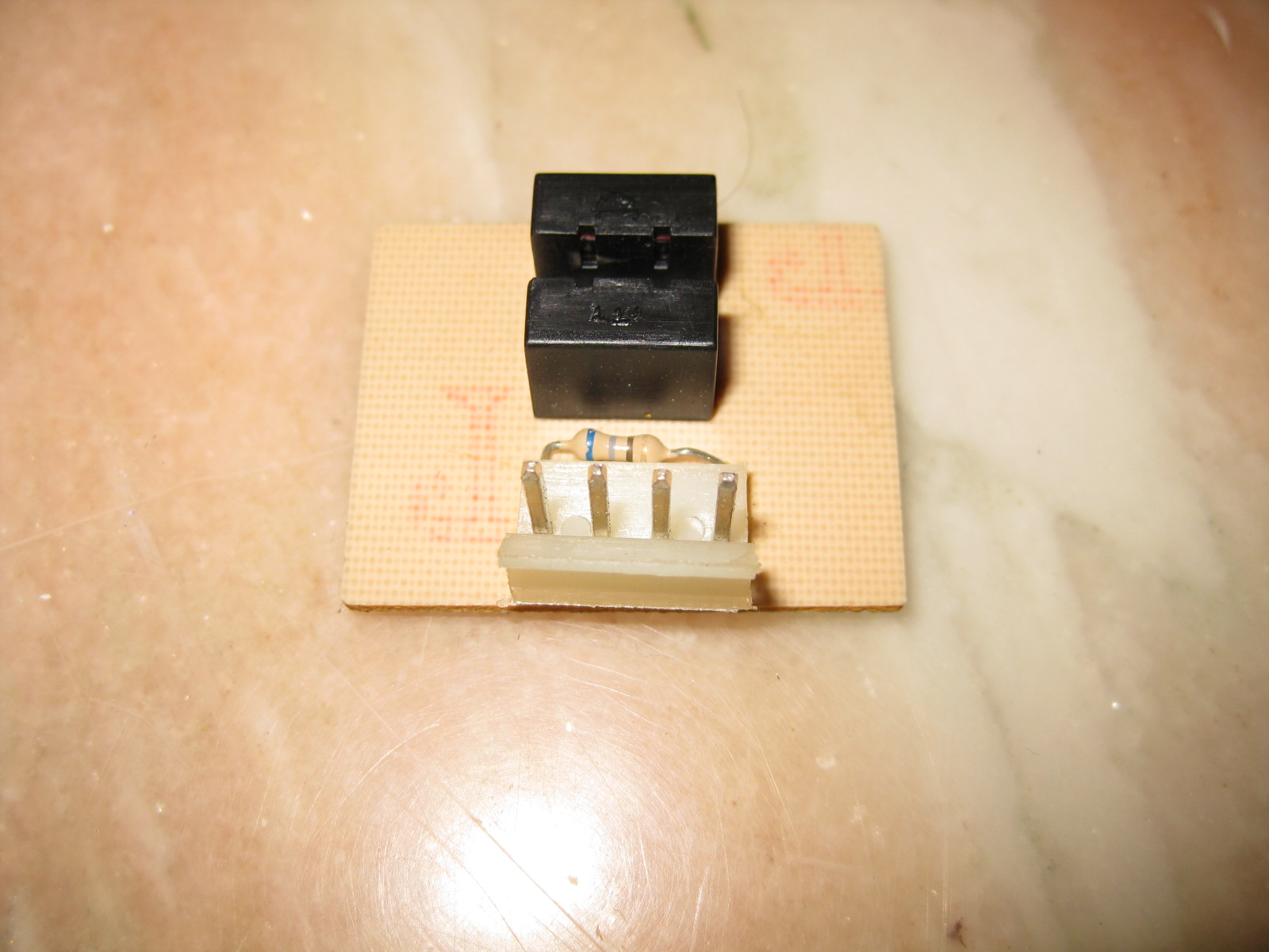
There are no ICs in the trackball which may be the issue.
So I'm looking for an actual mouse schematic of the M0100 mouse
Currently finding alot more info in the Atari/Amiga forums but would rather the real thing
I don't have one myself or I would of opened it up
Thanks
Where are you located? While I do not have a schematic I have probably over a dozen working M0100 mice. I'd gladly donate one to the cause for say $5 + shipping.
Send me a PM and let me know if you are interested. Might as well put some of the stuff to good use!
Zan
Hello Shaker68,
allthough i have not made a detailed shematic of the Applemouse,
i did make a probably usefull sketch about the topic:
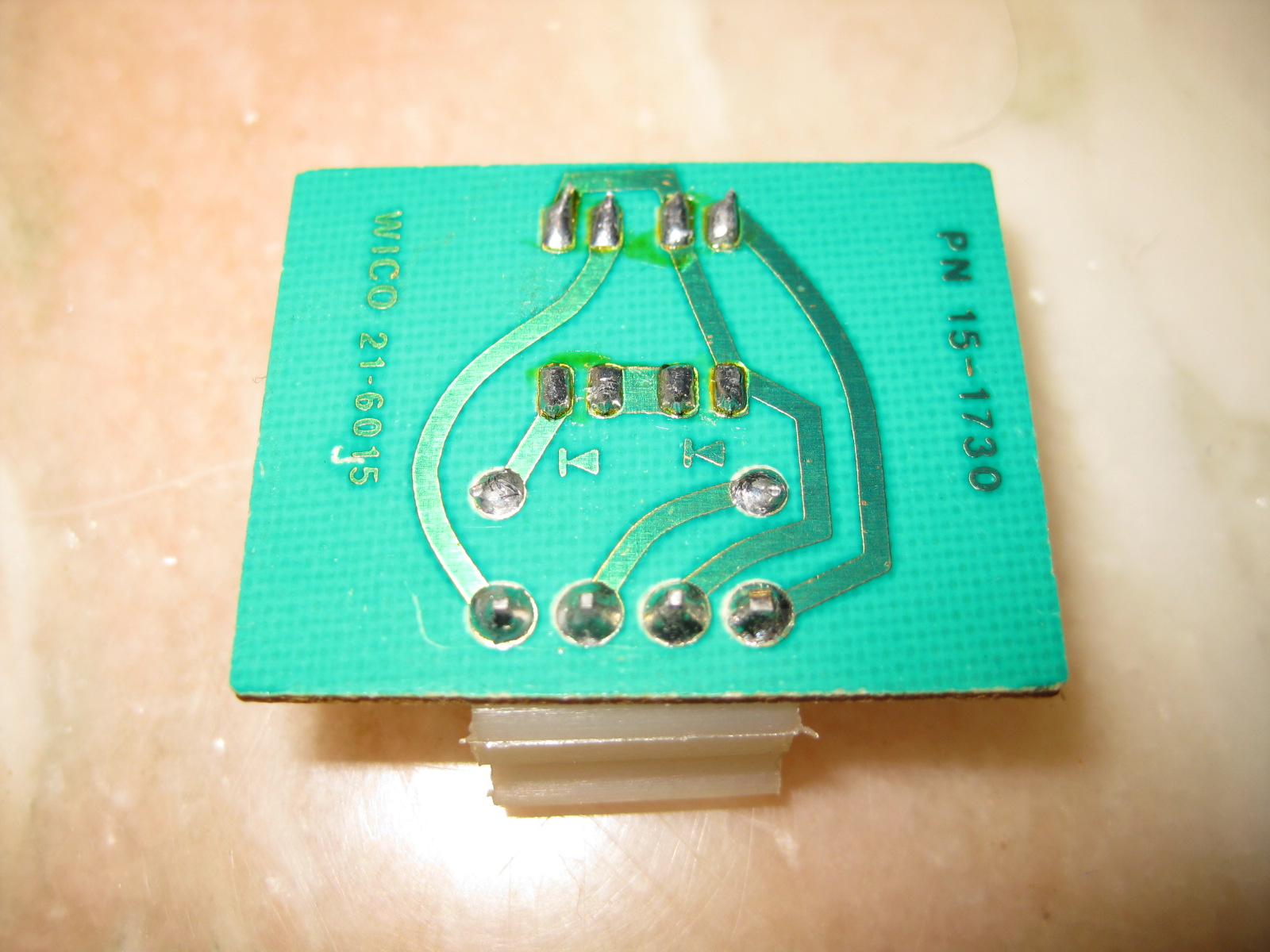
The sketch made was result of checking the topic for adapting a trackball about 30 years ago to the mouseinterface quite similar to the one you issued the pictures...
The Applemouse is indeed a rather simple device in basic...
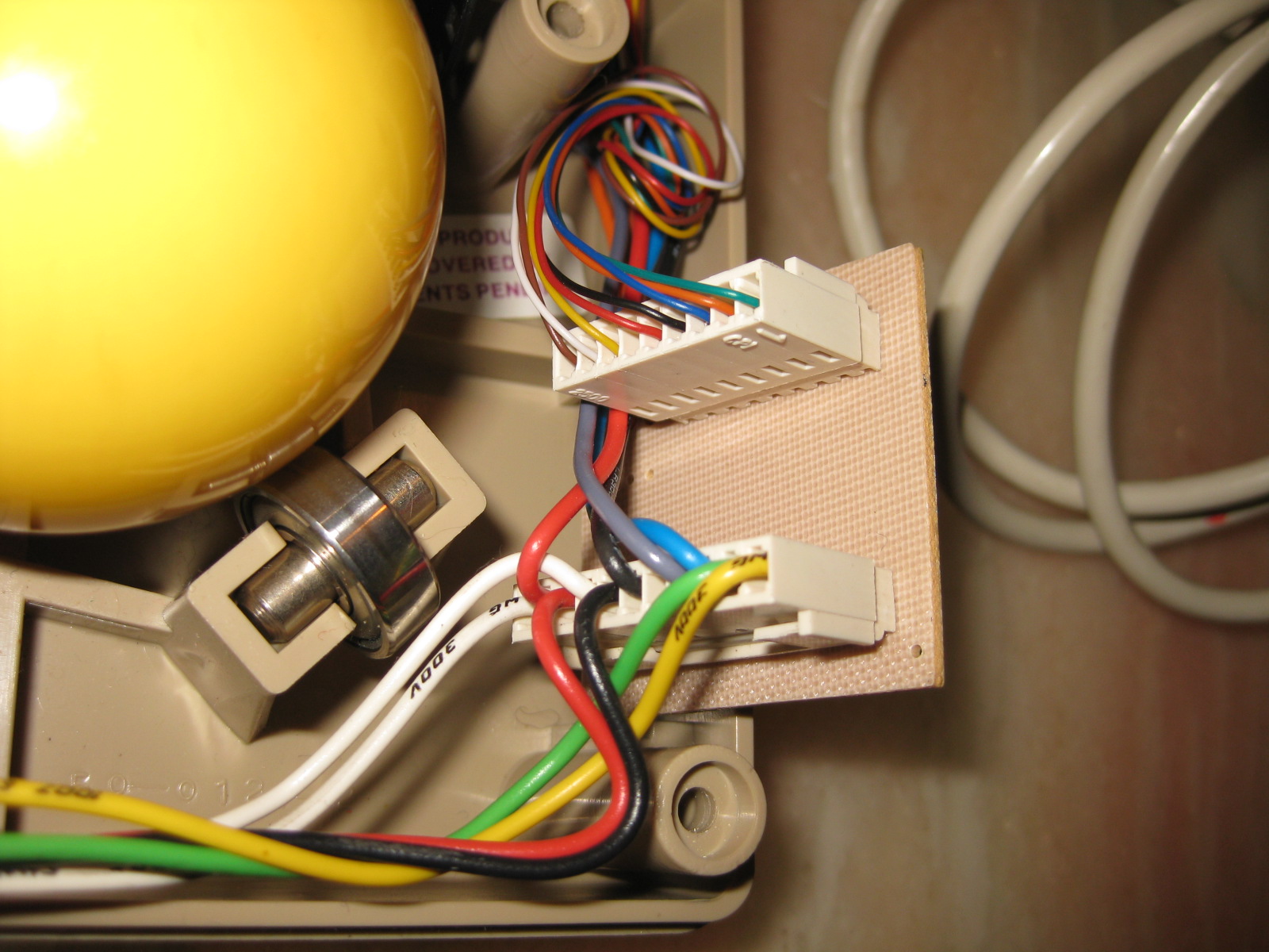
in general you might reduce the function to one switchbutton and 2 light-barrier-systems that transduce the movement of the ball by interrupting the lightbarrier with a punched wheel.
Pin 3 of the DB9 provides +5 Volt to the device to supply the electronic parts in the tracksball or mouse with powersource and
pin 5 is the ground or if you prefer the 0 Volt branch.
Pin 4 is the line that indicates the value of the switch ( pressed or not pressed ).
In that days i did not exactly examine if the pin 4 detects 0 Volt or +5 Volt to be active
but the switch as far as i remember was connected to +5 Volt and therefor it might be even recommended to put a "pulldown resistot" of 1 kiloOhm to Ground between pin 4 and pin 5 which result the pin 4 to keep at 0 Volt till button is pressed and then pin 4 raises to + 5 Volt till the button is released and then drops back to 0 Volt.
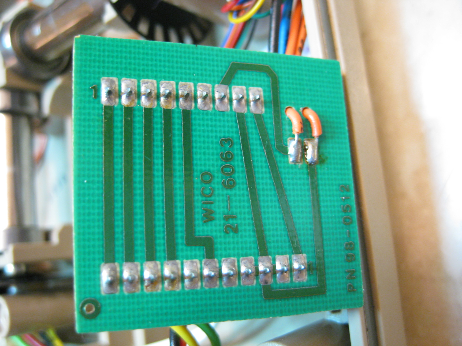
Pin 6 and pin 9 both lead to the trigger of the related latch resulting to the fact that if one of the two light-barrier-systems start transmitting pulses the card detects "activity at the ball" and therefor starts counting the pulses at pin 7 or pin 8 - this causes the card to act either to movement of the X-axis or Y-axis.
At the other hand pin 7 only transmits the pulses from the x-axis
- while pin 8 only transmits pulses from Y-axis.
To keep the reaction at pin 6 and pin 9 apart from eachother and avoiding influence to eachother it might be recommended
to mount one diode instead in the trace between pin 7 and pin 9 with cathode towards pin 9
and a second diode instead in the trace between pin 8 and pin 6 with cathode towards pin 6.
Between pin 3 (+5 Volt ) and the anode of the led in the light-barrier at both barriers a resister of 220 Ohm or 330 Ohm should be inserted ( in the sketch the light brown parts ) to limit the power in the LEDs as protection.
As well also at both phototransistors at the collector ( that´s the side without arrow ) the pin maybe better not connected direct to ground but instead connected with a 150 Ohm resistor to ground ( also as protection of the phototransistor ).
Of course if anybody puts up a detailed circuitplan it would be better stuff for proceeding,
but unless that is done the sketch might at least give an idea about the basic working....
sincerely speedyG
As always Speedy, fanastic writeup! on a side note. do you have any information on pinouts for koala pad?
Hello Mr.Fix,
i do believe to have them in the dungeans of my archive.....
but not just at hand now.... i´ve got to search it....
i´ll execute search tommorow or thursday cause at the moment i´m busy with other urgent task.
speedyG