
Hello,
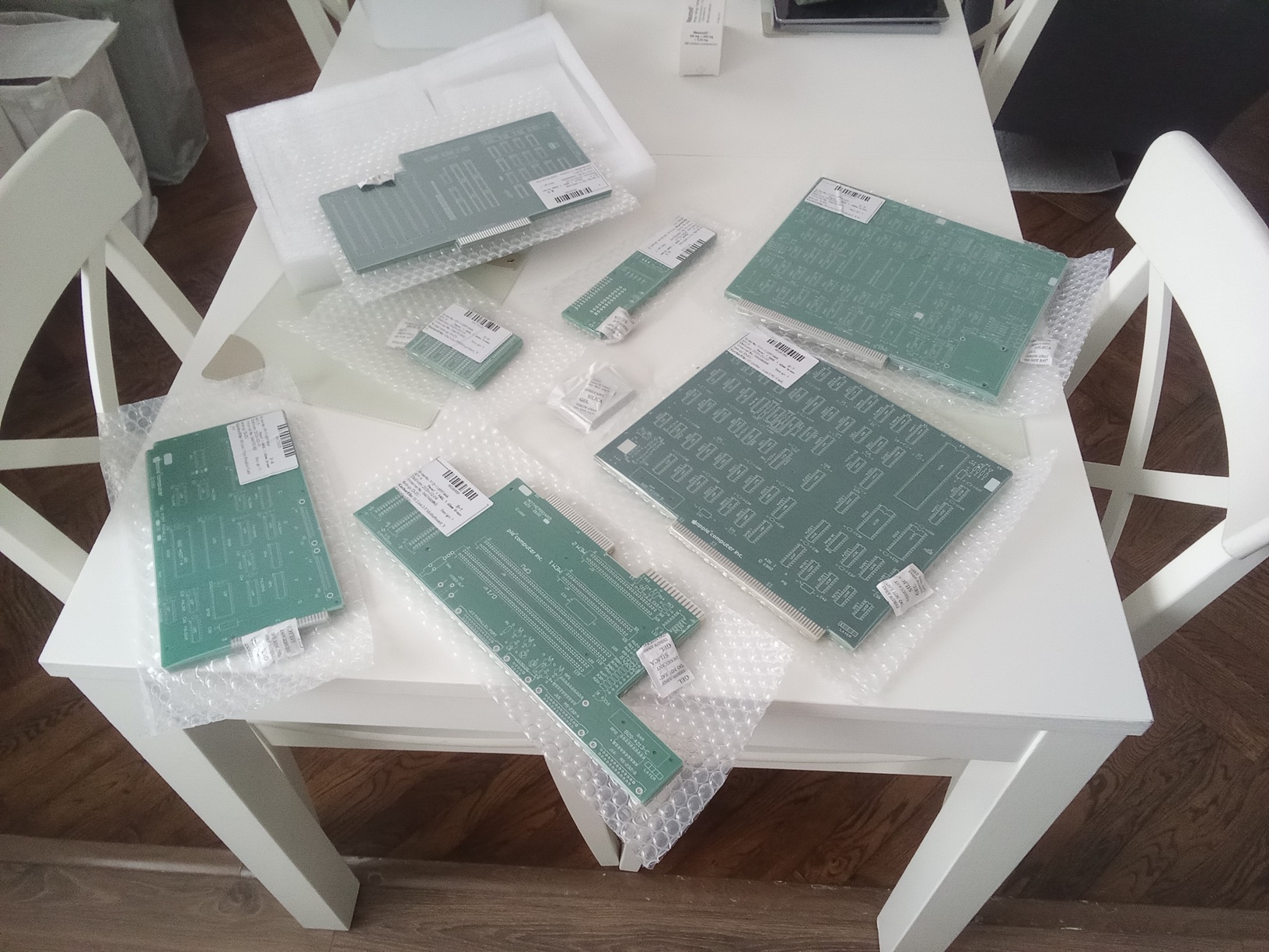
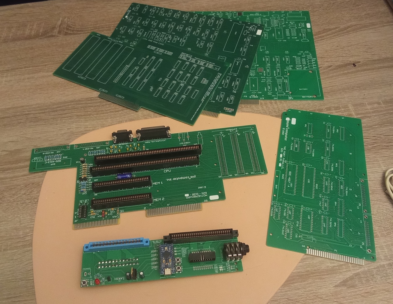
It's time to start another Apple replica project – this time, a Lisa. It's a bit of a wild ride compared to the Apple 1 and Apple II, but I'll give it a try. I'll try to post photos of the work in progress. I ordered all the boards from Gerber, available online (many thanks to their authors).
The thread title is not accidental. There will probably be a separate thread about trying to get this thing to work :)
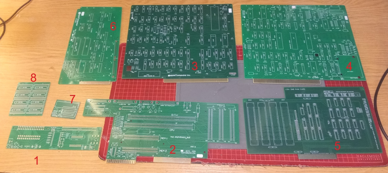
PCB Description:
1. Breakout board from https://github.com/RolandJuno/Lisa_Breakout
2. Motherboard from https://github.com/alexthecat123/Lisa-PCBs
3. CPU card from https://github.com/warmech/lisa-hardware
4. I/O card from https://github.com/alexthecat123/Lisa-PCBs
5. 2MB RAM card from https://github.com/warmech/lisa-hardware
6. 2Port Parallel Card from https://github.com/alexthecat123/Lisa-PCBs
7. COP402 to COP421 adapter from http://john.ccac.rwth-aachen.de:8000/patrick/COPSreader.htm
8. 6309 to 27C512 adapter from https://github.com/RolandJuno/Lisa-PROM
Looks amazing to me, the cost you expect for it to be complete?
Hey, All the boards (5pcs of each) cost $310 (including shipping). I estimate the cost of the electronic parts to be an additional $300. I had most of it
In post #3, 'SQ9PXB' wrote:
" Hey, All the boards (5pcs of each) cost $310 (including shipping). "
Uncle Bernie comments:
Wow, you still can get PCB at an affordable price. Since the U.S. tariffs on Chinese goods, there is no way for us to get cheap PCBs for our hobby anymore. No way to build a 'Lisa' or any other clone. A lot of my own projects for the Apple-1 and Apple II hobbyist scene had to be put on the back burner due to the tariffs. Waiting for better times where it becomes feasable again to get reasonably priced PCBs.
Only for very small PCBs, not larger than an Altoids tin box, U.S. based, tariff free sources like OSHPARK make sense. The naked PCB for my YAAK keyboard - which from JLCPCB pre tariff did cost $6 each - if made by OSHPARK would cost $110 each. Makes no sense to do that. From this example I'd estimate (area wise) that a set of Lisa clone PCBs from OSHPARK would cost more than $500 per set.
Outrageous. Nobody would want to build a Lisa clone if the PCBs cost that much.
- Uncle Bernie
On the bright side the money from the Tarrifs helps support Billionaires in their time of need....
You're absolutely right, $300 for 5 sets is a decent price, but only if I sell the remaining 4 sets, which I won't. So, for my purposes, it was the price for one set :) PCB production is also very expensive in Poland, especially 4-layer boards like the Lisa IO card.
I'll post more progress photos soon.
Why not? In Bulgaria for example we have a great solution to the minimum 5 PCB problem: whoever is doing the ordering keeps one or two and either gives the rest away or sells them at cost. Whoever receives them pays for the local shipping.
It's also a lot more fun when you are doing a build along with 2-3 other people.
Today I finished soldering the CPU and I/O boards.
COU_CARD.jpg
IO_CARD.jpg
In post #8, "SQ9PXB" wrote:
" The big unknown on the CPU board is the L1 coil in the signal generator circuit. "
Uncle Bernie comments:
It would help if you could attach a snip of this section of the schematic diagram to your post, so the purpose of this inductor can be found out and then the proper value can be calculated.
As I don't have Lisa schematics, I can only guess it might be the LC tank circuit for the NTSC color burst. If so, 47 uH is probably too much, too high Q factor in this circuit, when used in the Apple II, often leads to problems.
With the schematic snippet I could be of more help. Fascinating project of yours !
- Uncle Bernie
Here it is:
LisaGenerator3.png
LisaGenerator2.png
So the inductor is a low-pass filter, blocking the crystal's oscillation frequency so that it appears at the base of Q2 and is amplified into clk_out.
The value depends on whether the crystal is operating in a fundamental or overtone mode.
It looks like around 2.5 µH would set the corner frequency of the LPF at 19 MHz, which may be enough to get the crystal oscillating at 20.3 MHz. The fundamental mode is probably used, as I think the MC68000 in the Lisa is 5 MHz, and the clock is probably not higher than 4X that.
But I am not experienced in this type of oscillator circuit, so I may have erred somewhere.
It was a perfect hit. At 47uH, the oscillator didn't work properly. I didn't have a 2.2uH coil, but I used a 1uH one and it started correctly (below is the waveform - collector of Q2 transistor / U1E_2). Ah, and I used the 20.00MHz oscillator (20.37504MHz is unavailable, and I think it's pointless)
The CPU, I/O and SunREM 2MB cards are fully populated. I'm having trouble with the latter because it turns out my dual SIMM30 sockets (which I desoldered from a faulty PC486 board) don't fit this card. I need to buy new ones (and they're damn expensive).
COP421 emulator. The COP421 emulator using the Soviet KP1820BE1A chip appears to be working. Main Lisa soft power-up starts OKay, and communication between the COP402 and 2716 on emulator board shows signs of life – it seems to be OK.
I've captured oscilloscope traces for the MC68 processor's address and data bus, as well as the support circuits, and "there's life." This is promising. Unfortunately, my time window for this project has ended at this time. This is the most exciting part, but I have to postpone it for other things. Stay tuned.
1_Q2.jpg
2_COP.jpg
3_sunrem_problem.jpg
3_sunrem.jpg
IMG_20260221_222144.jpg
IMG_20260221_202257.jpg
IMG_20260221_174833.jpg
I'm glad you got it oscillating!
I don't know exactly how "square" the clock is supposed to look in this circuit, but it's a little pointy (like a triangle wave), and I wonder if that will cause problems later. It would be interesting to see the difference 2.2 µH makes: but I could just simulate it in LTSpice to see that way.
There are surprisingly many variations of SIMM sockets. Check to see if TE 2-382130-1 (low profile angled 27°, dual row on 0.500" centers) matches the row spacing between pins (if you can even find them, 30-pin SIMM sockets have been out of production for ages). If not, check if the Phoenix Connectors HWS9229 angled 22° with 0.500" (12.7 mm) between rows might fit. The angled socket style uses more distance between rows than the vertical socket style.
Hello friends,
Here's a quick update from the Apple Lisa build battlefield.
What's been done:
- Soldered in a single 30-pin SIMM socket from a local store
- Installed SIMM RAM chips with 80ns parity check (only BANK1 for now)
- Verified basic clock signals - OK
- Verified HSYNC and VSYNC signals - OK (22.4kHz and 60Hz)
- Verified Reset circuit operation - OK (and autoreset seems to be OK too, as the processor sometimes enters autoreset loops, but I don't know why only sometimes, and sometimes not...)
- Soft PowerON via COP421 adapter turns the power on correctly, but doesn't turn it off - this isn't the COP402/421 adapter's fault, perhaps something along the way - I haven't verified it yet.
There's no sound from the speaker. The screen only shows horizontal stripes/interference (the screen isn't designed for 22.4kHz, but if it's working properly, you should see an image—it's not there). But not all the chips are in place propertly yet:
CPU Board:
C1 location is 74LS169 instead of 74S169 (too slow?)
C2/D3 location is 74S260 instead of 74LS260 (maybe too fast?)
Below are the oscilloscope waveforms of the signals. I also designed a simple chassis for the CPU, IO, and RAM cards to prevent them from bumping into each other.
link to the 3D design and photos of what it looks like.
https://makerworld.com/pl/models/2447805-apple-lisa-minimal-chasis#profileId-2686967
Use it as you wish, modify it, but don't sell it.
00.RAM_1.jpg
00.RAM_2.jpg
01.Lisa_card_chasis_1.jpg
01.Lisa_card_chasis_2.jpg
02.CPU_PIN15_CLK.jpg
03.HSYNC_22_4.jpg
03.VSYNC_60Hz.jpg
04.Video_signal.jpg
Hi!
Today's update:
In location C2/D3, the 74S260 has been replaced with the recommended 74LS260 (but no effect).
I'm waiting for the remaining chips to arrive according to the documentation (74LS169/74S169 in location C1).
The RESET signal on PIN18 of the 68000 processor is short and then long - I'm attaching a waveform.
CRT monitor connected to the VIDEO OUT output looks as shown in the picture (the CRT doesn't support 22kHz, but it's sufficient for debugging).
Regards, Mateusz SQ9PXB
00_RST.jpg
01_Screen.jpg
Simm Adaptor 2.png
Simm Adapter.png
Hey, interesting idea with the adapter, but for single SIMM sockets you probably don't need it.
I used these connectors: https://allegro.pl/oferta/podstawka-pamieci-simm-30p-tht-17456175743 Unfortunately, there's no manufacturer number written on them.
The missing TTLs should arrive this week to fill the "S" / "LS" slots as required. Unfortunately, the SIMMs I have are three chips - MS514256 80ns (I don't know if they're too slow).... Can anyone give me some advice?
Regards,
Mateusz SQ9PXB
Two- or three- chip SIMMs usually won't work with older computers. The reason why is geometric.
Chips of all kinds are more efficient to produce when they are nearly square. There are some chips with long narrow shapes, but economically they are at a big disadvantage. Chip designers try to make them as close to square as they can.
Almost all the area on a DRAM chip is the memory array. To make the chip square, the memory needs to be square, too.
The memory array consists of a transisor and a capacitor, repeated millions of times vertically and horizontally. So to be square, it needs to have the same number of rows as columns. Now we really start to see why the chips are organized the way that they are. A chip with a million bits will be organized as a thousand rows and a thousand columns. (The real numbers are 1,024 rows and columns, for 1,048,576 bits.) When each column is a single bit wide, this makes it a 1M x 1 DRAM chip. Accessing the chip requires first sending it a row address, then a column address, then reading or writing the bit with that (row,column).
When each chip reads or writes a single bit at a time, they are referred to as "x 1" chips. A 30-pin SIMM is 8 data bits wide, so this requires 8 chips per SIMM, or 9 if parity is used. The way that two- or three-chip SIMMs can exist is that they use a different DRAM chip organization, with four data pins per chip, referred to as "x 4" chips. These are accessed by first sending it a row address, then a column address, then reading or writing four data bits at once.
But remember how the memory array needs to be square? The two-chip SIMM (a third chip is only for parity) to replace an eight-chip 1 Megabyte SIMM needs each of its two chips to hold four times as much. But they can't be organized using 1,024 rows, 1,024 columns, and four bit wide columns, because that would be a long, narrow rectangle. Instead, the 1M x 4 DRAM chips are organized as 2,048 rows, 512 columns, and 4 bits per column.
So you can see that two- or three-chip SIMMs are not logically equivalent to the 8- or 9-chip SIMMs of the same total capacity. The number of rows and columns used to access them is different. There are also differences in how refresh is performed (since all dynamic memories need to be refreshed on a continual basis), but those details don't need to be explained yet.
The Lisa uses parity, and the SIMM modules must be 9-chip. I read somewhere on a forum that someone successfully used 3-chip SIMMs in the Lisa, but they were 70ns or faster. So maybe the geometry issue won't be a problem? Unfortunately, I can't find the thread (it wasn't on this forum). I'd like to hear from anyone who has actually used 3-chip memory in the Lisa to confirm this.
I can no longer edit the above post.
The forum https://lisalist2.com/index.php/topic,456.msg3284.html#newindicates that 9-chip memory can work, but with a maximum refresh rate of 256 cycles/8ms. My 256kB SIMM modules (MSM514256) have 512 cycles/8ms, so they probably won't work. So Lisa's project will probably be on hold for a long time because of this.
Hi!Today I installed ALL the chips according to the documentation (“S”/“LS”), especially on the SunRem RAM card. Additionally, as a test, I replaced the L1 choke in the 20 MHz generator circuit on the CPU board from 1 µH to the previously mentioned 2.2 µH — this does not work. My oscillator started operating in overtone mode and generated 40 MHz waveform. I restored L1=1uH, and all clock signals are OK.
Today received pack from Danmark shop with 16pcs of brand new COP402N chips. I replaced one of them with previous Soviet version, but the behavior is identical (which reassures me that they both are functional).
Next:I connected the Hsync/Vsync/Video output to an RGBi/CGA/EGA → VGA converter and obtained a synchronized image. This is key. After powering on the Lisa, for several seconds (5–15 sec) an image appears with a few dots in the upper center, and then the display transitions into vertical lines. Without the SunRem RAM card (with what I believe are not equal SIMM modules), these stripes do not appear.
It's also important to note that the I/O card (specifically, the U7C 6522) doesn't generate any beeps. I'm currently debugging this card, but at first glance, everything seems OK.
I don't know Lisa at all, I don't know what behavior is appropriate and what isn't. It's a bit like wandering in a fog :)
0.COP402.jpg
1.40MHz_2_2uH.jpg
3.BOOT_1a.jpg
4.BOOT_.jpg
Thank you for doing the test with the 2.2 µH inductor! The result is very interesting, as it shows me I was incorrect in assuming it worked as a LPF. In a LPF, 1 µH should make a higher corner freq compared to 2.2 µH, but we see the opposite effect. I think what really happens is that the two transistors are a long tail pair and the inductor changes the phase angle between them. I need to study the circuit more.
Hi All!
Great progress today. I replaced the questionable 2114 SRAM on the CPU board with 2148, and everything (almost) started working immediately.
I/O card is working – the VIA 6522 produces sound, and the COP421 emulator now turns the computer on and off at the right time. But most importantly – we have a video, although it's very strang.
Watch the video
https://www.youtube.com/watch?v=YVHKWKQXhT0
I use the ACV-011 converter (it probably can't handle the 22kHz sync of Lisa video), but it gives some image.
The RAM SunRem card is still equipped with the same SIMM with 3 chips. Could this be the cause of the poor display? Or maybe my CGA to VGA converter isn't handling it. I don't know yet. The image is very strange, as if most of the bits are missing, but it's recognizable. Computer starts up, reports some errors during the self-test, but at this point it is a success.Possible causes:1. Bad SIMMs2. A malfunctioning CGA/EGA to VGA converter3. There's a problem on the CPU board.
Below are the current photos of my Lisa clone, as well as the appearance of the video converter and a comparison of the SRAM CPU A8/A9/A10 chips (good/bad - not working)
Regards
Mateusz SQ9PXB
5.boot_.jpg
1.Lisa_PXB_cpu.jpg
2.Lisa_PXB_io.jpg
3.CGA_2_VGA_ACV_011.jpg
4_sram_OK.jpg
What do the error beeps mean?
In my case I hear LO-HI-HI.
which indicates a memory error.
Well, I'm actively searching for suitable SIMM modules.
BTW. Please help me set up a Raspberry-based RGB2HDMI video converter. What kind of adapter should I look for? I have no experience with this.
Hello!
Today, two 256kB 9-chip SIMM modules arrived. After installing them in the MEM1 slot (the other slots are empty), the "strange" image remained unchanged. However, the error appears much faster now: a LO-LO-HI BEEP (CPU error, which doesn't occur with 3-chip SIMM modules - strange). The SIMMs tested in a PC machine work correctly.
Something else happened, though. I connected a LisaKeys keyboard emulator (Arduino UNO with a USB Host shield) to initially test its functionality. Unfortunately, the keyboard didn't respond (although communication was established – verified with an oscilloscope). But I'll leave that for later. More importantly, this time I heard a BEEP HI, HI, HI, which means that the CPU, RAM, and IO tests were running, and the error was "Startup device invalid/failure." After checking the pinout of the Apple II floppy drive with the pinout of the breakoutboard, it turned out that the pinouts were (almost) identical, and nothing would be damaged. I took a chance, and the Apple II floppy wants to read the floppy disk!!! You can especially hear the head activity just before the HI, HI, HI error pops up. I know this drive won't work here, but for testing purposes, it showed that the drive controller was trying to communicate with it, and the computer was freezing late in the boot process.
Unfortunately, a good video converter is essential.I ordered a PCB and parts for the RGB2HDMI build, but it will take some time to arrive and get it soldered (and working properly).
Regards,
Mateusz SQ9PXB
IMG_20260309_180515.jpg
256simm.jpg
I found a my big mistake in the 20 MHz oscillator circuit on the CPU board — I had accidentally swapped the (L1) 1 µH inductor with the (R15) 47 Ω resistor. Below is a comparison of the oscilloscope traces.
Hi All,
Another milestone.
I found a my big mistake in the 20 MHz oscillator circuit on the CPU board — I had accidentally swapped the (L1) 1 µH inductor with the (R15) 47 Ω resistor. Below is a comparison of the oscilloscope traces.
Interestingly, the waveforms going to the CPU, as well as the video HSync and VSync signals, looked correct. However, because the base waveform itself had a poor shape, the resulting video signal also looked bad. So it turns out it wasn’t the cheap CGA video converter after all (and credit to it for displaying an image it wasn’t really designed for surprisingly well).
I'm still using 3-chip SIMM modules and they seem to work fine. My recently acquired 9-chip SIMMs give an error early in the Lisa Autotest.
In the meantime, I’ll build an RGB2HDMI converter to get a clean, pixel-perfect image.
I also want to repeat the test with the L1 = 2.2 µH inductor, since the previous attempt was flawed. I’ll run that test soon and share the results (hopefully without the strange overtone effects this time).
I also managed to enter service mode using the Arduino/USB keyboard emulator (Lisakeys) and type “Hello World”
Next step: getting the mouse working.
Video showing how it starts now:
https://www.youtube.com/watch?v=G24oRWya7oc
Photos from the self-test below.
1_L1_R15_Comparea.jpg
3_boot.jpg
4_boot.jpg
5_service_mode.jpg
6_all.jpeg
Those two components look almost identical... Great you have come so far, great work!
Hi!
Another milestone.
Today I soldered the RGB2HDMI CPLD board and the remaining components (without the analog board) – everything works with the Apple Lisa. I'm using the TTL version, because that's how it connects to the Apple Lisa (HSync, VSync, Video, and GND). The analog RGB2HDMI PCB will have to wait until later.My Apple Lisa replica gives a good picture and video. What's more, it appears to be a working device. The keyboard (emulator) works fine. I'll be enabling the mouse and the "ProfileHDD" drive soon.
Picture story below
0a.RGB2HDMI.jpg
0b.RGB2HDMI.jpg
1.Autotest.jpg
2.Boot_error.jpg
3.Service_mode_serial_number.jpg
4.Service_mode_test_dump.jpg
73! SQ9PXB
Hello !
Today I tested the CPU CARD with a choke of L1=2.2uH – everything works. The Lisa is booting. The waveform is below (L1=2.2uH). Sorry for the confusion. But due to my mistake, I discovered some new strange behavior with a distorted 20MHz waveform.
BTW, as part of my meditation and reflection, I soldered another new Lisa/CPU board – it booted without any problems. (Photo below)
L1-okay.jpg
CPU card.jpg
Regards, SQ9PXB
P.S.
If someone is bothered by high-resolution photos, they don't have to look at them (although I reduce them anyway), but I've experienced many times that such photos are very useful.
Success!
Arduinofile Profile emulator is working correctly. And also pre-tested the 2-port parallel card. It reports correctly in the system, but I haven't checked anything else.
I was able to run Macworks and LisaOS 3.1!!! I'm very happy.
Importantly, the Sunrem RAM card isn't working entirely correctly. When activating more than one memory bank, it reports a memory error. Currently, the system boots with MEM1 256kB (3 chips SIMM). And those vertical stripes... But I bet it could also be the RAM card's fault, because it's the same on the second CPU board, and it's the same without the IO card too.
Now I "only" need a mouse :)
As usual, the story is in pictures below And a video showing the full boot of LisaOS.
https://www.youtube.com/watch?v=ofiA71iXorM&t=5s
0_Arduinoprofile.jpg
1_paralel.jpg
3_macworks.jpg
3a_macworks.jpg
4_LisaOS_BOOT.jpg
4a_LisaOS_desktop.jpg
Regards,
Mateusz SQ9PXB
Update: The vertical stripes issue has been resolved. The culprit was the RGB2HDMI settings. (Sampling menu->Setup mode: Normal change to Set pixel H Offset resolved the issue.
IMG_20260322_211202.jpg
IMG_20260322_211418.jpg
I found a snippet of the manual for the SUN Remarketing card online. It says that if I'm using it as the only card in the system, bank 2 must be empty. That would explain my problems when trying to use banks 1 and 2. I'll resolder the SIMM connectors from bank 2 to 3 and check again. Unfortunately, I don't have any more SIMM sockets.
sunrem.png
Another day at the construction site :)
The mouse is working! I used an Amiga-PS2 mouse adapter for Arduino.
Project: https://github.com/glitterkitty/Arduino-PS2-Mouse-to-Amiga-Adapter
I have a few PS/2 to C64 adapter PCBs, and I'll use them when porting the above project to make it compact.
The RAM also works; my Lisa has a working 1MB of RAM (still 3chips SIMM modules, but now in MEM1 and MEM4 banks) and runs LisaOS, MacWorks (and Plus), and Xenix correctly.
Everything works :)
1mysz.jpg
2mysz.jpg
3lisaos_clock.jpg
4RAM.jpg
5ram.jpg
Hello, after a short break during which I was busy with other things, I had less time for Lisa
BUT... To make sure she wouldn't be lonely, I built a second Lisa, and now we have two Lisas :)
I also built an DB25M from Lisa to DB9F adapter that combines null modem functions with a USB/Full RS232 cable. Terminal communication works, but XMODEM file transfer from the BIU doesn't – I'll leave it at that for now.
At this stage, I consider the Lisa project completed. When I have time, I'll build a case for her....Best regards, and here are a few photos.
0_lisa_1.jpg
0_lisa_2.jpg
2_rs232.jpg
2a_rs232.jpg
3_terminal.jpg
Splendid job!
Hello after a long break.
I haven't done much on the Lisa replica in that time.However, I soldered two dual-parallel card replicas – one for the 6522, the other for the 6522A – both work correctly.
I also soldered an ESProfile emulator (now I have ESProfile and Arduinofile – thank you, Alex Anderson-McLeod, for your wonderful projects!!)
For testing purposes, I connected the ArduinoFile to the motherboard and the ESProfile to the Parallel card – both drives are recognized in MacWorkPlus, everything works. However, I encountered a problem – I can't boot the Lisa from the external parallel card - error code 85.
Everything is in the picture story.
Thank you and best regards,
0_IMG_20260520_195736.jpg
1.MacWorks_plus_mount.jpg
2.Boot_error_from_external_parallel.jpg
This whole project is pretty amazing! The Lisa was a really dream system for a lot of people back in the day. Most of us could never imagine being able to addord one. The only real opportunity was when companies were selling them on the surplus market like Sun Remarketing. Even then I didn't have the spare $$$ to buy one. Around that time I bought a used Mac Plus and hacked together enough to get that and a small by today's standard SCSI drive running using used parts. I later added an accellerator and a slightly larger new SCSI drive. Eventually I upgraded to a Mac II with an accellerator and later a IIfx, Then I switched over to Linux as my primary platform and any Macs I had were secondary after that.
Hi!
I salvaged two dual SIMM sockets (lying flat) from a damaged 286 motherboard, so I used them in the second RAM card and moved the recovered vertical slots to the first RAM card. Now I have one card with a full complement of sockets.
There's not much else going on with this project.....
I plan to print a 1:1 scale enclosure (I've already made some progress on this, but more on that another time).
Regards
Mateusz SQ9PXB
1.jpg
2.jpg
3.jpg