Anonymous
User login
Please support the defense of Ukraine.
Direct or via Unclutter App
Active forum topics
Recent content
Navigation
No Ads.
No Trackers.
No Social Media.
All Content Locally Hosted.
Built on Free Software.
We have complied with zero government requests for information.
Comments
Nice mod!
Nice mod!
that looks hot!@
that looks hot!@
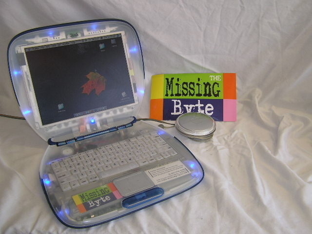
first clear clamshell I can recall seeing . . .
'cept for my 'prototype' ClearClam demo.


.
.
.
Nice job you've done too, though I'm not crazy about flashy-glowy-lighty things. I think it looks great overall.
Can you show some details? eg: the slotload optical's bezel and the BT module
dan k
BT module & Drive Bezel -
I just got a new HDD on order for the Cybook, so when i take her apart, i'll get some Pictures of the bezel close-up, and a how-to on the wiring .
Hoop
UPDATE!!
The 80 gb hard drive install went very smoothly, now running on a Western Digital Scorpio 80gb 5400rpm.
While I had the machine apart, I decided to clear up some wiring issues.
The LED lighting has beed re-wired to use only one side of the DPST switch(no biggie)
But my Bluetooth mod is having issues.
Ive decided to use the other side of the switch to run a small relay pack to switch the USB from internal to external.
i will be using a bundle of 2 super tiny reed-type SPST 5v relays to switch the 2 USB data wires at the same time.
the drive for the coils is using the 5v USB power run w/a current limiting resistor, switched byt the same switch as the LEDs.
My parts should arrive today, i'll have a wiring diagram and some more pictures before the end of the week
-Hoop
More Updates!
The Bluetooth How-to is done !
Parts needed:
* USB BT module(i used the Microsoft Module that came w/my mouse)
* 20-22Ga Wire (I used old phone cord and a USB-b cable)
* SPST Switch(I used a DPDT)
* 2x W117SIP-6 Magnecraft 5v Relays.
* 1x 47Ohm 1/8W 5% Resistor
I still wanted use of the USB port so direct wiring of the Port was Out ... or was it .
The Wiring is as Follows
4 wires from bottom of USB port
* Power +5v from usb jack to switch
* Data+ to Relay
* Data- to Relay
* GND to USB Cable
Next,
* +5v from switch to USB cable
* +5v to Positive side of relay coils
* Data- relay to USB cable
* Data+ realy to USB cable
Finally-
* Neg- side of relay coils to Resistor
* resistor to board ground
Now-
With The relay pack installed and wired, the Bluetooth and the LEDs Light when the switch is ON.
When the Switch is OFF the USB port is free to be used, and the LEDS are off .
Viola! Reassemble and you have Bluetooth at the flip of a switch !
Visit http://www.the-missing-byte.com/cybook.html for more info!
Im startign to toy with the idea of selling this one
Im starting to toy with the idea of selling this one to finance my Key lime project ....
any input other than eBay ?
its up !
Now available on Ebay !
Feel free to bid !
http://cgi.ebay.com/ws/eBayISAPI.dll?ViewItem&ssPageName=ADME:L:LCA:US:11&item=9738361318