
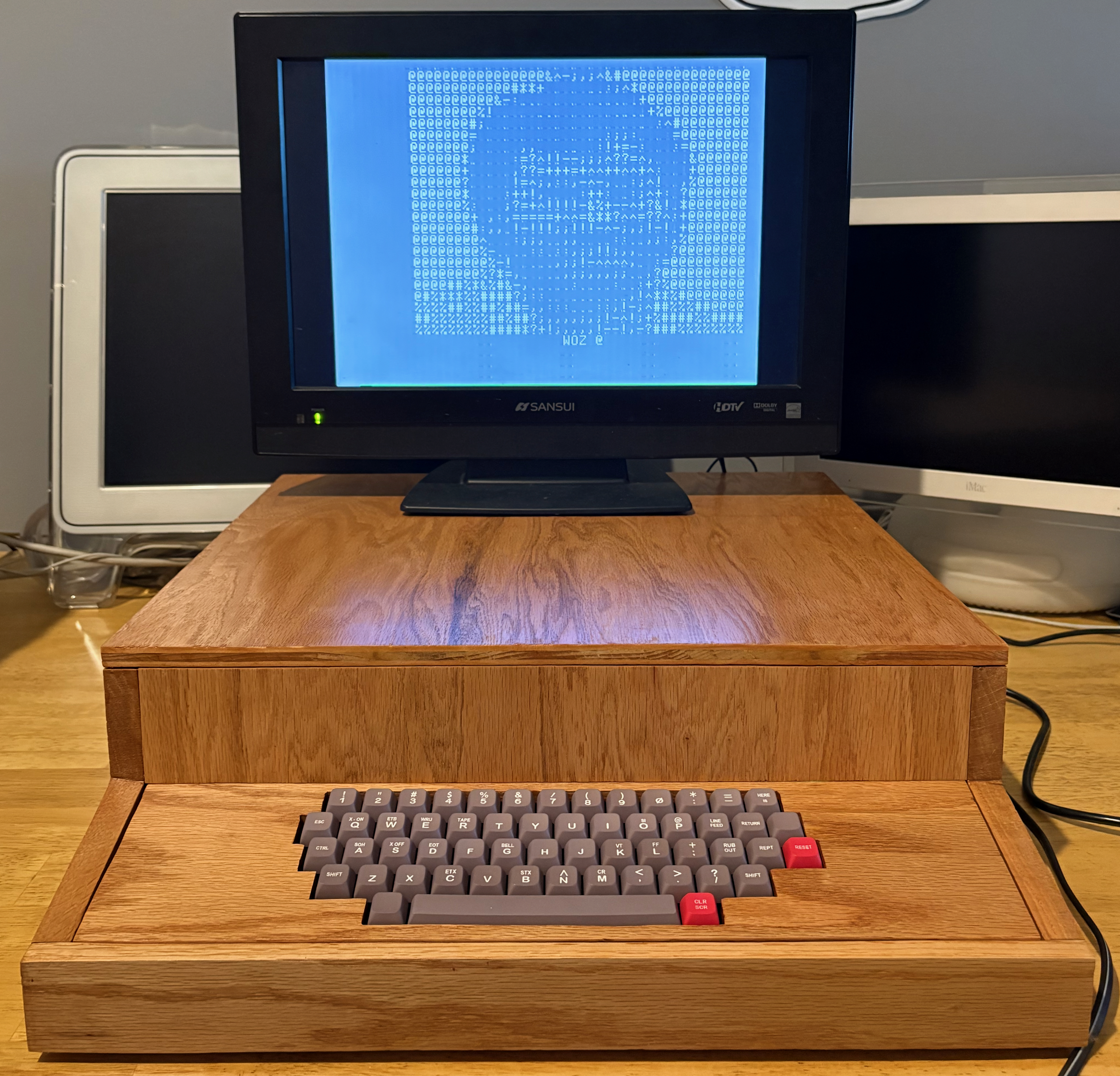
Just finished the case a couple of days ago.I started this project in July 2025.Got a first video in October but wrong characters…Back to it in December and after different IC checks, got it running by Xmas!Here is a little bit of the process
https://www.applefritter.com/content/new-apple-1-come-alive-sick
Took me 2 months to finalize the case, and here it is
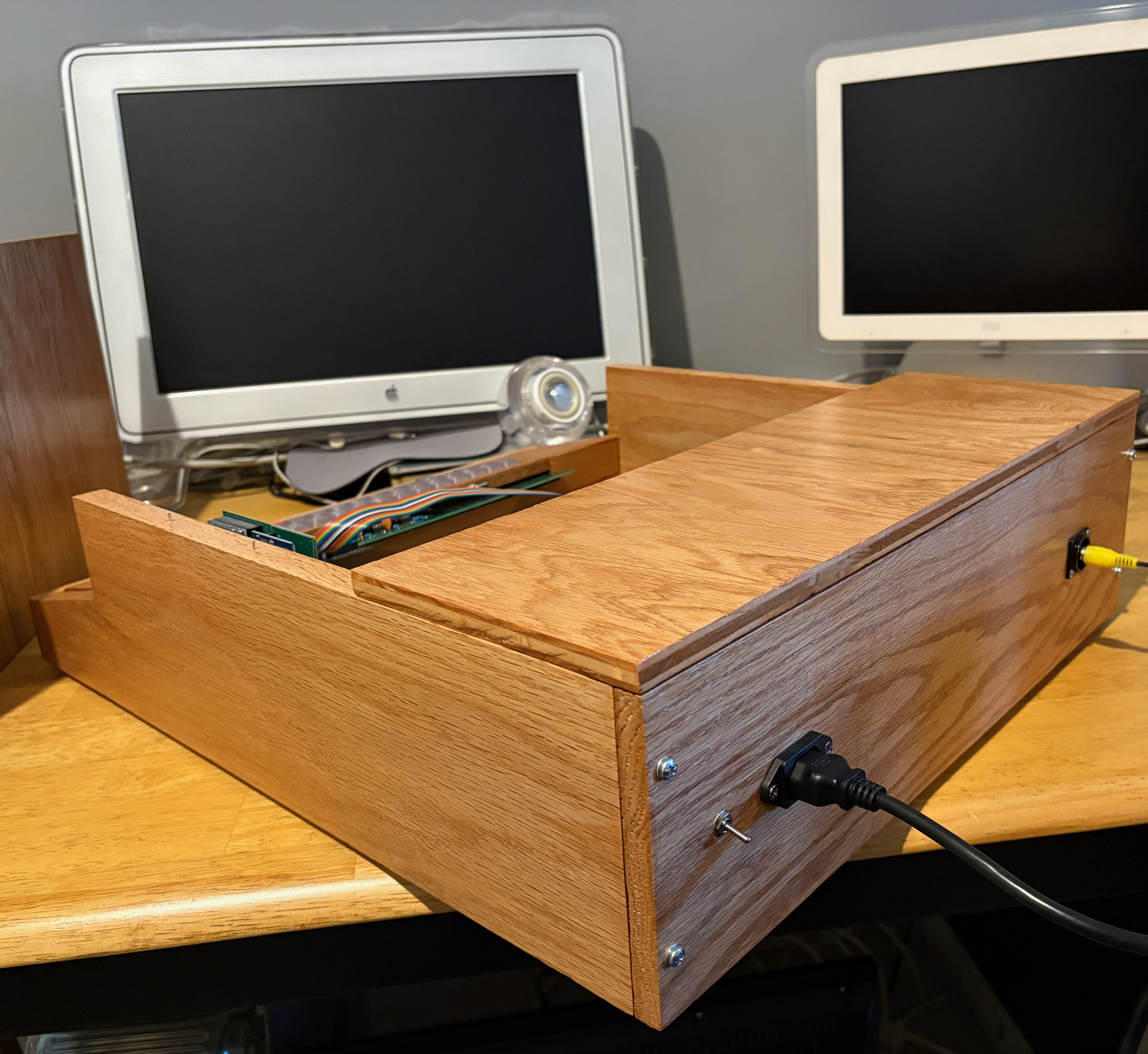
Congratulations, well done! Beautiful case, I like the integrated, but partitioned power supply.
I still have to drill some holes to allow a nice flow of air to cool the LM 323, that's why there is that hole in the partition of the power supply.
Great job.!!
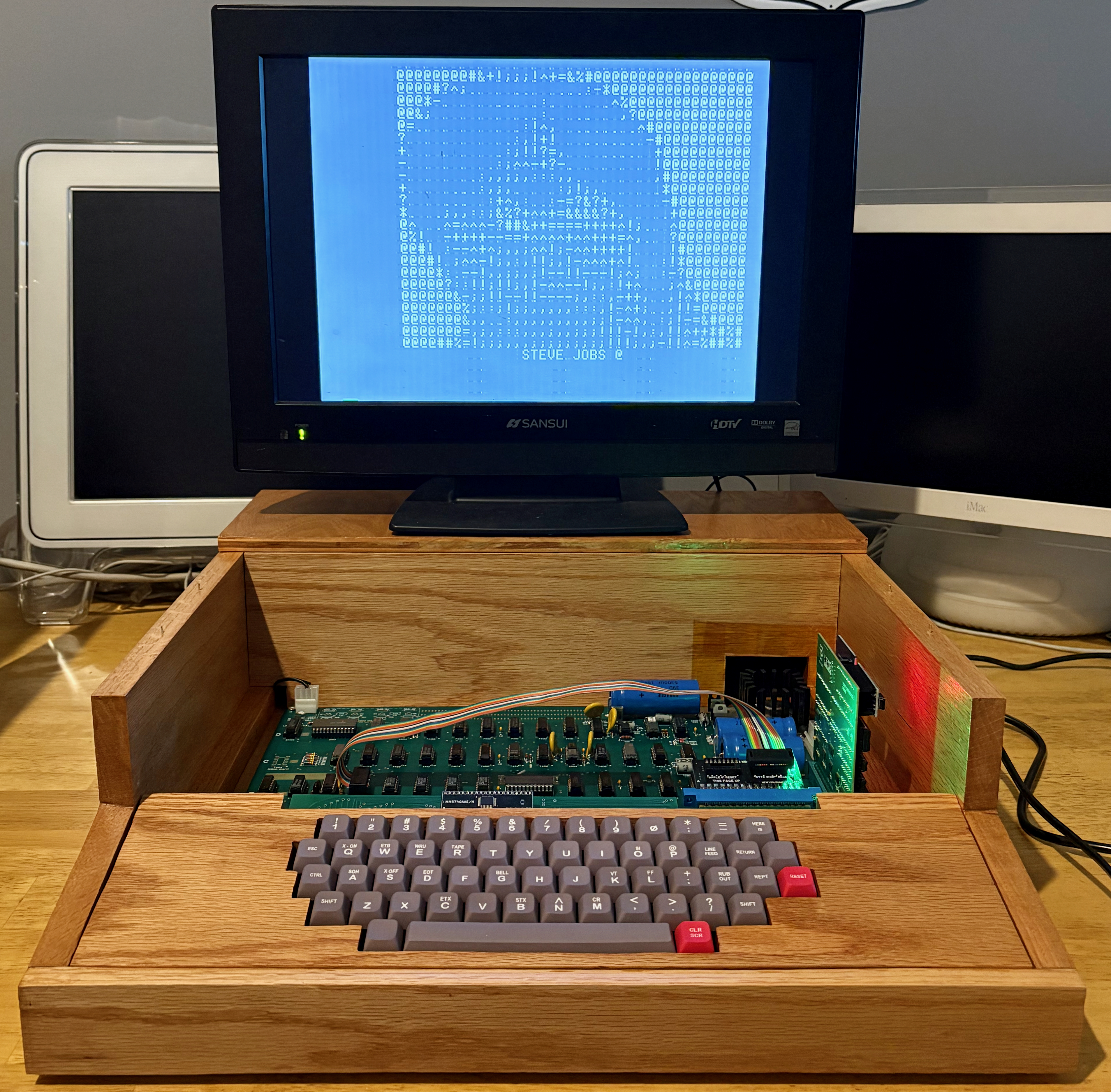
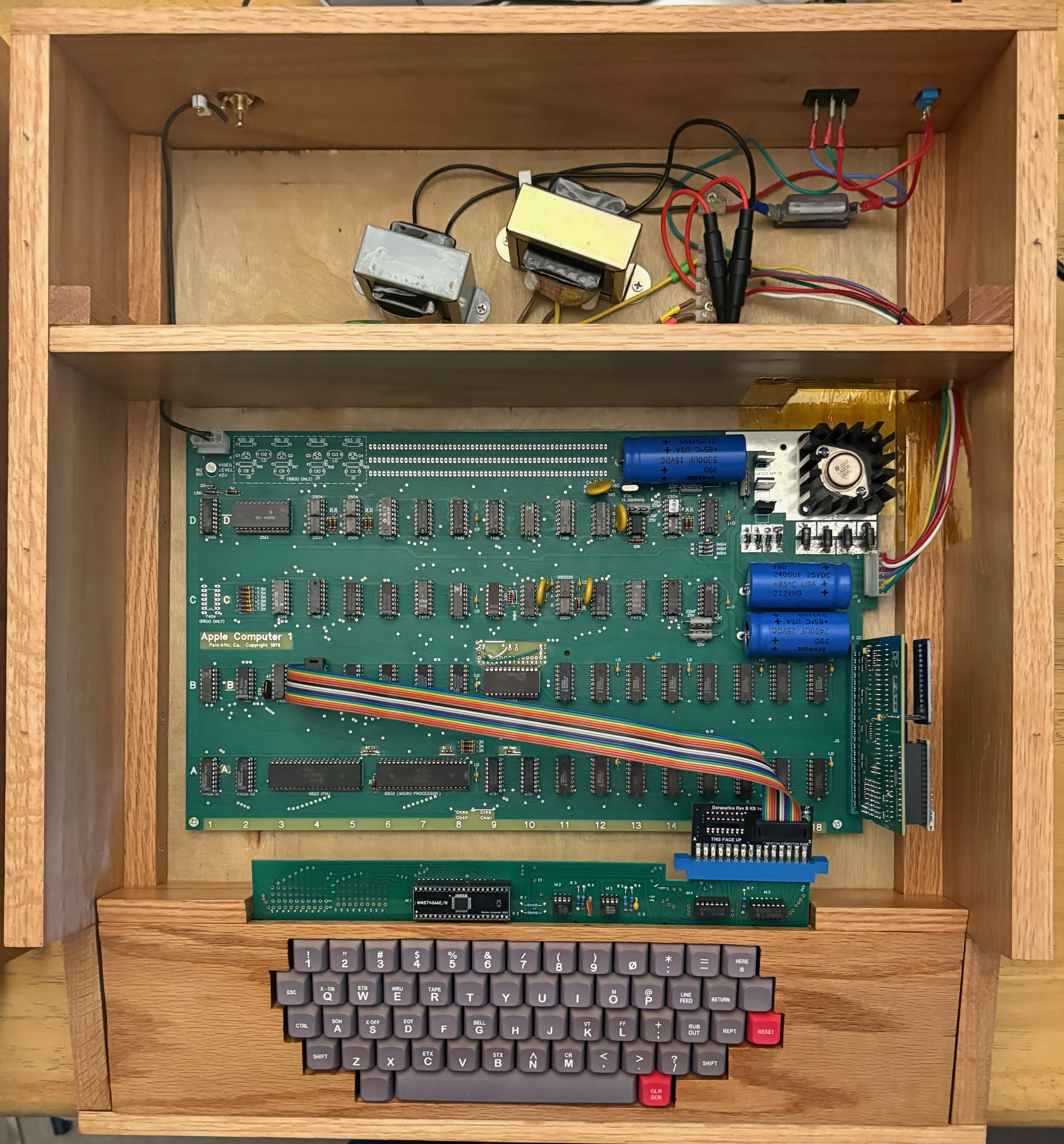
The case is gorgeous, I really like it. Congratulations on your perseverance in achieving success! The Apple 1 board itself looks great too!
Do you have the R12 potentiometer turned all the way up? The image is quite pale...
My replica never got a case; all I did was screw the PCB to a laser-engraved flat board :)
Regards,
Mateusz SQ9PXB
It could also be the sync on the monitor. I noticed sometimes a modern monitor will look that way, or worse. I think Uncle Bernie has a mod to fix this, but I am usually working with the real thing, so not modifying anything.
For the OP, the transformers may get hot, and the LM323K will need some air. I would suggest an actual FAN blowing across the entire power supply area and having a place for the hot air to escape. The smaller regulators can also get hot and have no heat sinks other than what is built into the regulator. You will experience issues with your case and could have a regulator short out from the heat, sending unregulated power to the board and frying components if you do not take this into account. Outside a case, the board can get hot, but potentially run for hours at room temperature (65 to 80F) without an issue, once you restrict and contain airflow over the heat sink for the LM323K, it will make everything worse as it throws heat into the entire case. For my original byteshop case, it has a lot of hidden vent areas, but I still put a fan blowing into the rear mesh air vent, which then escapes from under the board into an extensive vent section that is covered with mesh.
Thanks for your comments!
R12 position depend on the monitor.
When I use an old CRT, it is at 80-90%.
B1.jpeg
With a modern monitor, 50% plus is ok
Apple-1 Borgmac 1.jpg
May be the picture with the modern monitor was taken with R12 at 90%.
Here is a picture at 50%.
B2 50.jpeg
Hi,
In my opinion, the image is too pale for the monitor's brightness. Perhaps the output Q5 transistor's gain is too low? I would also check the signal levels on 74166 pin 13 and check R1 (1.5k) or maybe change it to e.g. 1.3k as a test?
See how it looks on my low quality LCD monitor. And video - loading 30th demo from PC - on CRT display. The video is not interesting, but you can see the "brightness" of the displayed text
https://youtu.be/39vHQxcpAXA?si=X1bWJ2hoVULsM9Zr
Or maybe everything is fine, it just looks that way in the photos? :)
Regards,
Mateusz
IMG-20220507-WA0000.jpg
As a transformer for the + 5V power supply (LM323K), I propose a transformer with a secondary range of 7.5-8.5V (not more). In this case, your stabilizer will not get very hot. (Some people cook eggs on it).
Regards,
Mateusz SQ9PXB
IMG_9205.png
I made a couple of tests while setting the monitors the best I can and reducing external lights.
Around 50% with old LCD monitor, I think I got close to your example. Voltage is at 1.6 Vpp (yellow). 74166 pin 13 is at 4.1 Vpp (blue)
LCD.jpeg
50%.jpeg
100% with CRT monitor, voltage is at 3.3 Vpp
CRT.jpeg
100%.jpeg
I know about Uncle Bernie has a mod, should try it one of these days.
Oh yes, the picture looks very nice now.
I still admire your case, it's beautiful.
Regards, Mateusz
First big thanks to Uncel Bernie Mod, I am now abble to use a small monitor that did not handle Apple Vsync!
Here it is
Video Signal Board.jpeg
I had to use a trim pot and made some tests. Best setting is probably for me with a RC at 2.0 K
A few pics, including the shortened HSYNC
Video Signal Modification Uncle Bernie.jpg