
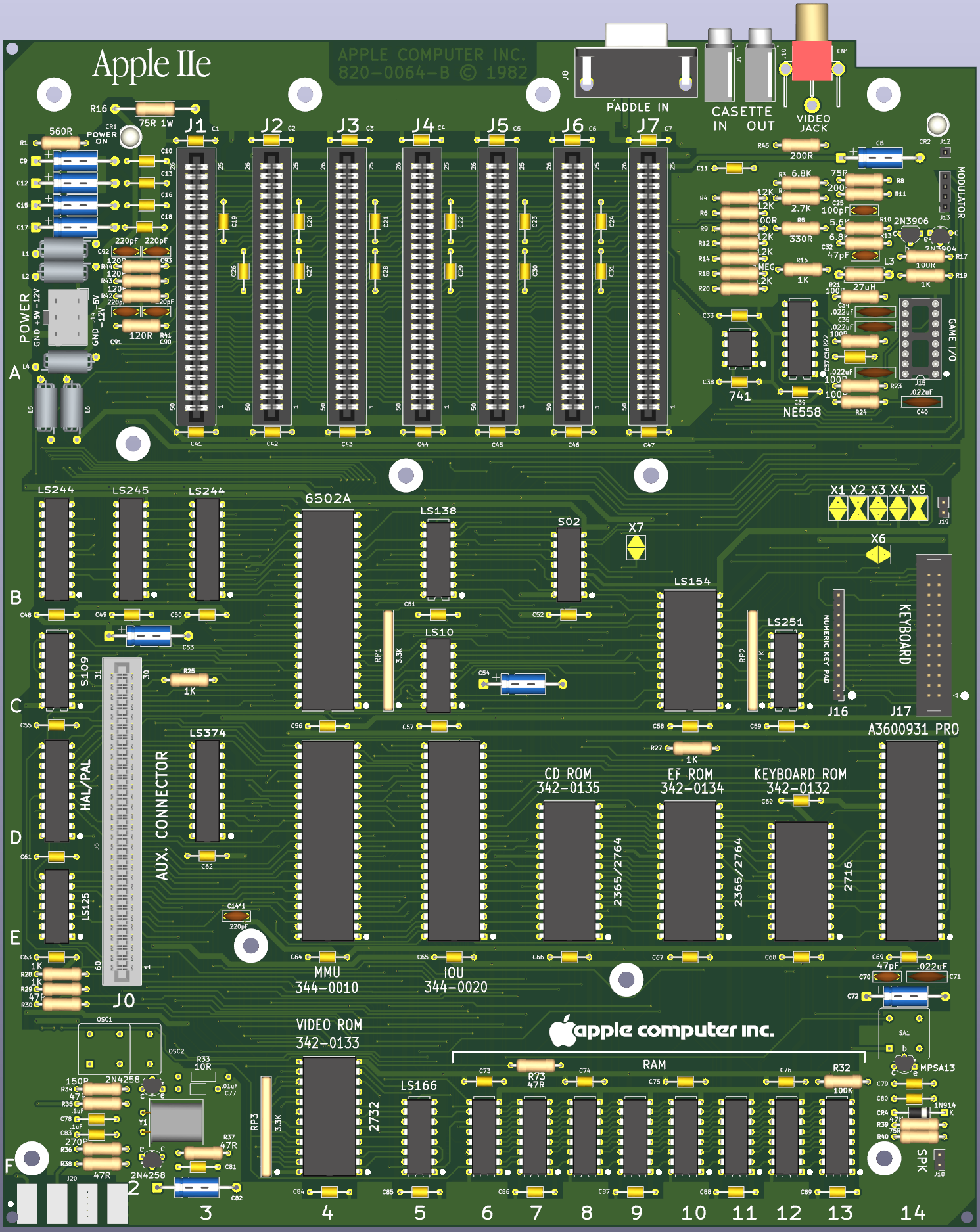
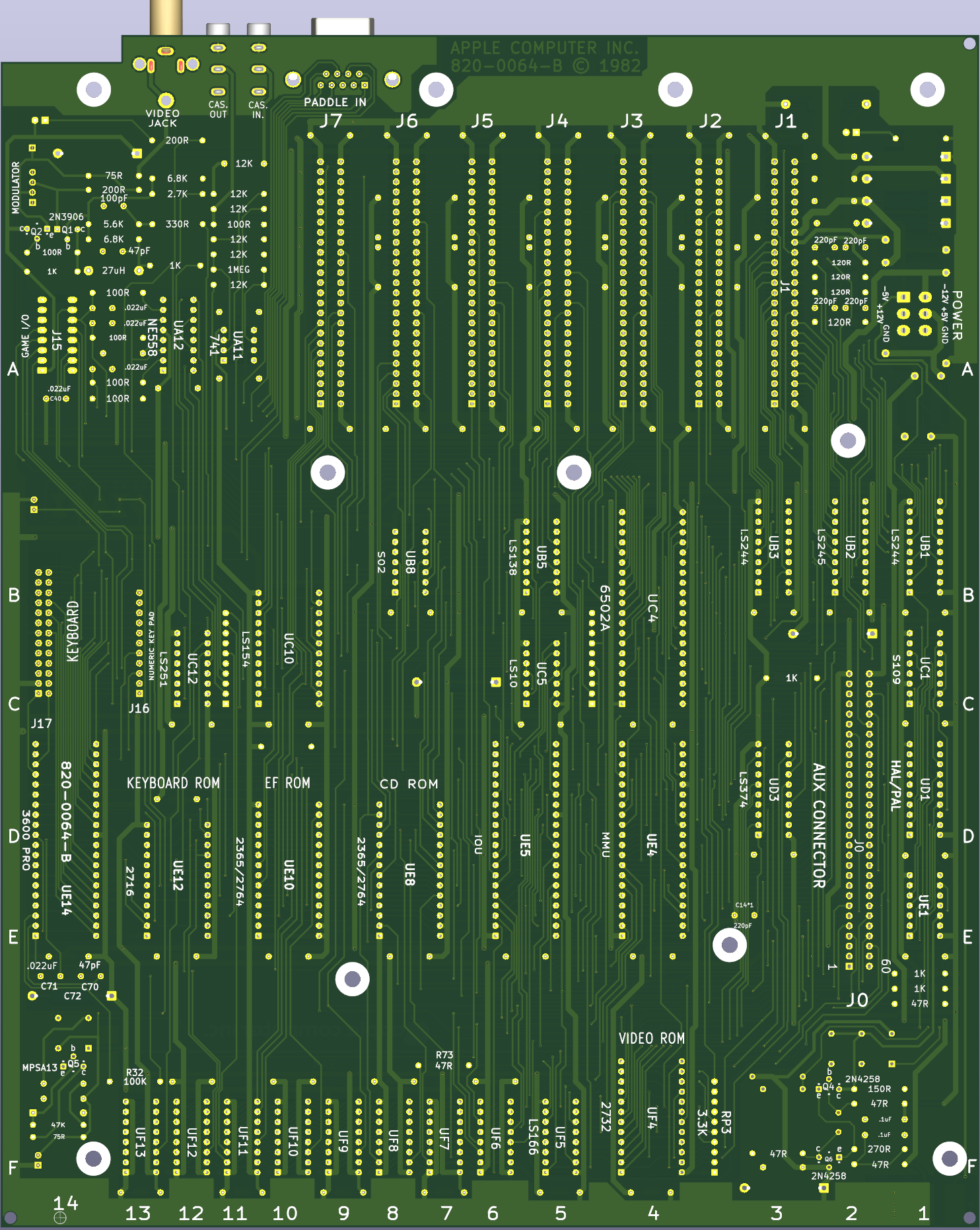
I found the schematic in KiCad format on baldengineer's "bit-preserve Apple IIe" page on GitHub. Building on that, I started creating the printed circuit board. Here is the result.
Anonymous
User login
Please support the defense of Ukraine.
Direct or via Unclutter App
Active forum topics
Recent content
Navigation
No Ads.
No Trackers.
No Social Media.
All Content Locally Hosted.
Built on Free Software.
We have complied with zero government requests for information.
A non-exhaustive list of errors identified on the schematic diagram (some errors are illustrated in the attached images):
1. The wiring of the J14 connector corresponds to the PCB,
2. Missing power lines: • UB1, 2, 3, 5 • UC10,12 • UD1,3 • UF5
3. Visual removal of unnecessary components from the PCB layout,
4. Adding the missing OE to the UF4 and connecting it to the corresponding pin of the UE5,
5. Correction of incorrect edge connector wiring,
6. Wiring of the UC1 (74S109) integrated circuit according to the original schematic diagram.
01_adding missing power pins.png
02_removed not needed parts from board.png
03_Added missing OE to UF4.png
04_on Conector wrong placed_one of them.png
05A_incorrect.png
06 corrected connection.png
Now that the MMU and IOU replicas have been created, building an Apple //e replica seems like the perfect solution. Great work—I hope you’ll be able to see it through to the end. I’ll be following the progress of this project, and thank you for sharing.