| Attachment | Size |
|---|---|
| 126.39 KB | |
| 26.53 KB |
I tried to build a DIN8 to DB25 serial cable to connect an Apple ImageWriter II printer to my Apple IIe with a super serial card. I followed the interface spec in ImageWriter II technical reference manual to make the cable but it doesn't work. The printer passed self test and loopback test. The super serial card works with ADT Pro. So I assume the issue is probably the cable.
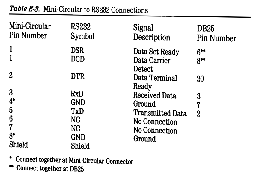
Below is the spec that I followed.
DIN8 DB25
1 DSR 6,8
1 DCD 6,8
2 DTR 20
3 RxD 3
4 GND 7
5 TxD 2
8 GND
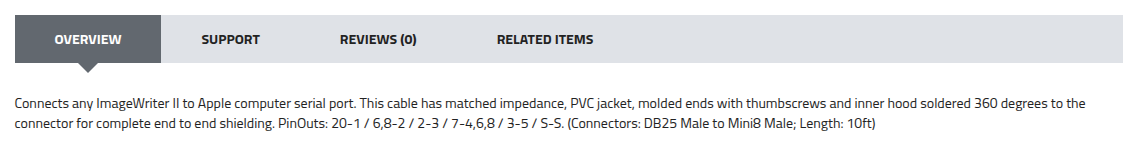
Interestingly I then found a different spec from the description of an DIN8 to DB25 cable for Image II printer for sale here: https://www.cablesdirect.com/store/p/2836.aspx. I tried to buy the cable but never got a response from the seller.
DIN8 DB25
1 DSR 20
2 DTR 6,8
3 RxD 2
4 GND 7
5 TxD 3
6 GND 7
8 GND 7
Anyone happen to know which spec is correct? Or would you be able to measure the pinout of your DIN8 to DB25 cable for ImageWriter II if you happen to have one?
I found this via Google search:
A Mini-DIN 8 to DB25 serial cable for the Apple IIe (typically for a Super Serial Card to an ImageWriter printer) connects the 8-pin round connector to a 25-pin D-sub connector. The standard configuration maps the Apple IIe serial transmit, receive, and ground lines to the corresponding DB25 printer pins.
Typical DIN8 to DB25 Pinout (ImageWriter II Cable)
DIN8 Pin 1 (HSKo) -> DB25 Pin 20 (DTR - Data Terminal Ready)DIN8 Pin 3 (TxD-) -> DB25 Pin 3 (RXD - Receive Data - Crossed to match TX/RX)DIN8 Pin 4 (GND) -> DB25 Pin 7 (Signal Ground)DIN8 Pin 5 (RxD-) -> DB25 Pin 2 (TXD - Transmit Data - Crossed to match TX/RX)DIN8 Pin 7 (HSKi) -> DB25 Pin 4 (RTS - Request to Send) or DB25 Pin 5 (CTS)
Key ConsiderationsSuper Serial Card: Requires the card to be configured as a printer, usually with a block connector.
Hope this is useful.
Joe
Looks like slop rather than a search result (although the two are increasingly indistinguishable because content farms occupy the top page of many search results)
The SSC has a built-in null modem switch, that reverses the direction of the TXD, RXD, and handshake lines. In the position with the jumper block's arrow pointing to "MODEM", the null-modem is turned off, since you don't use null-modems when a real modem (DCE) is connected to a computer (DTE). When the arrow is pointing to "TERMINAL", the null-modem is switched on.
Printers are wired as DTEs, like computers/terminals and unlike modems. So connecting a computer to a printer via serial cable always requires the employment of a null-modem in some form (null modem cable, external box, or the built-in jumper block of the SSC). But two such devices will cancel out, making it impossible for the computer and printer to communicate.
So if the MiniDIN-8 to DB25 cable is wired straight-thru, as a normal serial cable, you need to point the jumper block to "TERMINAL"; if the cable is wired as a null modem (TXD wired to RXD etc), you need to point the jumper block to "MODEM".
Here is the schematic detail that shows the jumper block:
SSC jumper.png
When it is in the position pictured, that is the MODEM position. TXD on the DB-25 port connects to jumper pin 6, which links straight across to pin 11, connecting to pin 8 on the serial driver U6A.
If the jumper diagram is rotated 180°, it links 6 to 5, which connects to pin 10 of the serial receiver U7A.
Thank you for all the replies! Once I switched the jumper block on the SSC to the Modem mode, the printer started to work with the computer. The diagram in the ImageWriter technical reference manul is for a null-modem cable rather than a printer cable that I expected.