| Attachment | Size |
|---|---|
| 595.79 KB | |
| 456.57 KB |
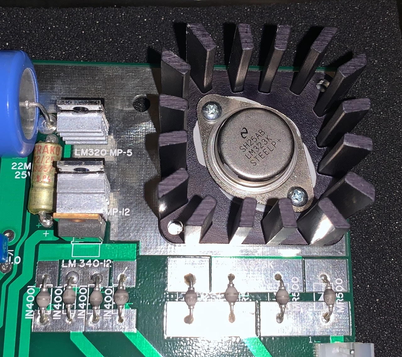
I have been installing parts on my NTI Newton board and I just put on the LM323K. I haven't powered it up yet, because I am unsure how to know if the thermal grease or the heatsink will cause a short. Should I put some type of insulation around the pins on the regular? Is this just one of those things where it works or you fry it? The holes in the lm323k are smaller than the heatsink, so trusting those to take up the slack and center it seems risky too. Maybe this isnt a big deal, but I have poured a considerable amount of time and money into this board and it seems like I should ask if anyone else has had a problem at this point.
[quote=WrongDateCode]
I have been installing parts on my NTI Newton board and I just put on the LM323K. I haven't powered it up yet, because I am unsure how to know if the thermal grease or the heatsink will cause a short. Should I put some type of insulation around the pins on the regular? Is this just one of those things where it works or you fry it? The holes in the lm323k are smaller than the heatsink, so trusting those to take up the slack and center it seems risky too. Maybe this isnt a big deal, but I have poured a considerable amount of time and money into this board and it seems like I should ask if anyone else has had a problem at this point.
[/quote]
I'd be more worried about your heat sinks on the smaller regulators touching.
If you use the correct RAM and have a small fan blow on the whole area, you don't need the heat sinks on the smaller regulators. Some RAM chips like the Intel ones can use extra current and cause the smaller regulators to really heat up.
As for the large LM323k, you should be fine, in fact you put a lot of thermal paste on it. you may want to clean some off using a qtip and ISP. It won't harm anything with the extra compound, it's just cosmetic.
Cheers,
Corey
You can use an ohm-meter to check for shorts between the input (pin closest to top of board), output (the other pin) and ground (case of the LM323k) or any other signal that you are concerned about.
regards,
Mike Willegal
Thanks for the suggestions. I think I am ok as far as the short goes, did use the ohmmeter to test. The lm323k seems to only be putting out 4.8v. I tried both of the ones I have (same part from same place) and they are the same. When I light up the board with the video section populated I get a flashing between D and $ and @ and blank. See images. I had lots of fits and starts because I am not sure what parts are good and not. However, while playing with a logic probe I noticed that when I touch the 2504 chips at D5 on pins 5 or 6 it seems to start smoothing the problem out. Is this a voltage drop problem? Is the 4.8v too low?
E1624EFD-3017-41DD-9342-EC60FDCD7F1A.jpeg
EC3A8B82-C06E-461A-BB2E-B7E4D650F1B1.jpeg
Did a bunch more troubleshooting and also found a neat chart from another post on walking through the 25xx chips to validate they work.
for what ever reason I cant have more than 2x 2504 chips in d4 and d5 or it garbles everything. Looking at the scematic I replaced all chips that could be in the line, c4 74157, c3 2519, and even d2 2513. No change. Am I missing something obvious? Should I start removing and replacing sockets? I did retouch all solder joints. My 7.5k resistors all test ok, but seem to vary between 7.8k and 8.1k. The board is an NTI Newton AC1 rev B1.
[quote=WrongDateCode]
Did a bunch more troubleshooting and also found a neat chart from another post on walking through the 25xx chips to validate they work.
for what ever reason I cant have more than 2x 2504 chips in d4 and d5 or it garbles everything. Looking at the scematic I replaced all chips that could be in the line, c4 74157, c3 2519, and even d2 2513. No change. Am I missing something obvious? Should I start removing and replacing sockets? I did retouch all solder joints. My 7.5k resistors all test ok, but seem to vary between 7.8k and 8.1k. The board is an NTI Newton AC1 rev B1.
[/quote]
OK, so you did the first obvious thing and looked for cold solder joints by retouching up everything, how about the opposite. Did you check if you had solder bridges? before I put my brain in troubleshooting mode to help, visually inspect the board under magnification.
Ok, I combed over the board with a magnifying glass again and it looks good.
New thought and question, should the @ blinking always have a blank space next to it? Mine doesnt. I put the 2513 on a logic analizer and I was a little shocked by how noisy the address pins are. This seems like it has to be part of my problem. It feels like the lows are not sticking, but again I have nothing to compare with. can someone post a good 2513 capture screenshot?
59311B58-BF7A-4E59-B1D8-151E2BE4892F.jpeg
[quote=WrongDateCode]
Ok, I combed over the board with a magnifying glass again and it looks good.
New thought and question, should the @ blinking always have a blank space next to it? Mine doesnt. I put the 2513 on a logic analizer and I was a little shocked by how noisy the address pins are. This seems like it has to be part of my problem. It feels like the lows are not sticking, but again I have nothing to compare with. can someone post a good 2513 capture screenshot?
59311B58-BF7A-4E59-B1D8-151E2BE4892F.jpeg
[/quote]
I should be able to do logic proble capture towards the end of the week. My workbench is covered with parts from a papertape reader project I'm finishing up right now. Can you wait?
Yes I can definitely wait... I had to clean up all my toys for a holiday party over the weekend. So it will be a few days before I can dig everything back out. Thanks for doing that. My plan be is to just build a second board, I am just waiting on some back ordered stuff from mouser, but should have everything for board 2 in a few weeks. It is hard to tell what is going on when I dont know what right looks like.
Here is a capture of all the 2513 address lines during the boot screen on my Mimeo.
[quote=Corey986]Here is a capture of all the 2513 address lines during the boot screen on my Mimeo. [img]https://www.applefritter.com/files/styles/95-percent/public/2019/12/15/2513_Apple-1_addressLines_boot.png[/img][/quote]
That will help a ton. Thanks! I will let you know what I discover. Sadly that doesnt look too different from what I show.