
| Attachment | Size |
|---|---|
| 668.68 KB | |
| 616.46 KB |
Dear folks,
I'm actually having an A.U.G.E. clock for repair action and do need some SW as well as libraries to be able to test the card right after having finalized the repair actions.
I know that there is some stuff at the Apple-Box from Harro... but this did'nt help me here. So if someone is having such card and some relevant software I would appreciate if he/she would share this information with me.
I'm also interested in getting the ROM content... or how to readout the content of the EPROM 2708 installed at the card without using an EPROM burner... because mine can't read 2708 but 2716... yes I know how to build an adapter but I'd like to get the content using my Apple IIe.
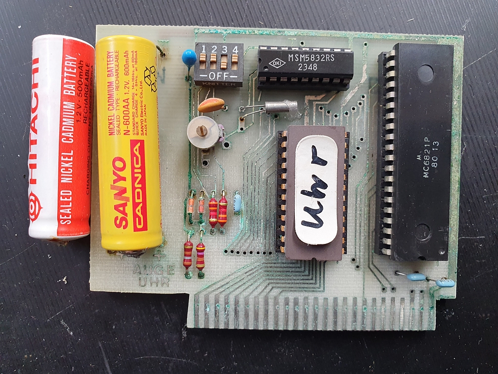
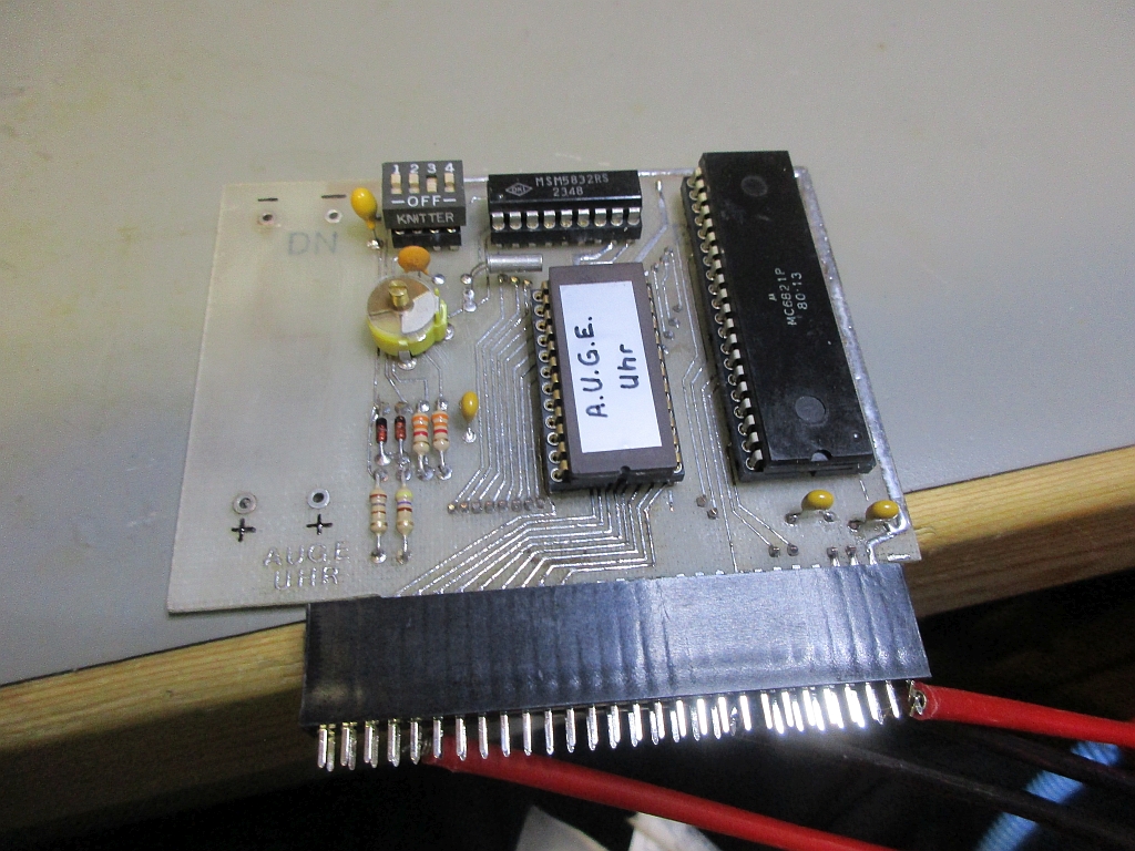
Beside some pictures of the repair action's so far:
Maybe RalfK has some insights ?
Hi Tokabln, it's been a while since we've worked on a project. I see you're still active in all of this, which is good.
Looks like you did a really nice job cleaning up that circuit board. Looks quite different from the original condition for sure.
I did a little searching on this clock module and came across the AUGE Clock page but I'm not sure if it's the same one you found.
This one has the schematic and some code to it. Might all the code that exists, I don't know, but just in case it's different from what you found:
https://www.applefritter.com/appleii-box/H021_AppleIIAugeClockPage.htm
Appears to be written in German language. Also check out "next Page" in the URL, as there is more to it.
Hope this is helpful.
There are schematics. The old hand-written one is ok. But the modern one is not free of error: add a connection to Vcc (+5V) between D2 and R1.
Another error: DMA IN is connected to DMA out, same with INT IN and OUT.
Regards
Ralf
I've got my board from the storage and cleaned the solder side with isopropyl. Means no restauration until now.
There are differences: no "AUGE UHR" but "clock" on the component side. And there is a logo on the upper right corner which is not on the AUGE board. The layout seems to be the same but it is not. There a lot of minor non functional differences.
Means: my board is not the AUGE board. Probably this is a predecessor or a compatible copy.
http://www.ralf-kiefer.de/A2/AUGE_Uhr/uhrbs3c.JPG
http://www.ralf-kiefer.de/A2/AUGE_Uhr/uhrls1c.JPG
I recognized that another owner had cut the traces for DMA IN/OUT and INT IN/OUT. I will repair this.
You can dump the contents of the ROM with (assuming in slot 4):
C400.C4FFL
C800.CFFFL
You can replace the List command with a Move or just write the contents to Disk with BSAVE (assuming you've already booted DOS).
BTW, that NiCd battery will not work on this board. The 5832 needs at least 2.2V (after the diode drop) so normally the battery woud be 3.6V (3 NiCd cells or 3V lithium).
There is no diode between the NiCd cells and the MSM5832. There is just a resistor. But the way these NiCd cells are loaded is not the best method.
I think that two cells are sufficient for the RTC chip. But three cells would be better to be loaded without too much voltage.
Hmm. I see a couple of diodes there at the bottom of the board. There would have to be to allow charging the battery but disallow having the battery try to supply power to the entire computer. It looks like the board is meant to have two batteries connected in series side by side (or possibly a three-cell stacked battery). But 2 cells would barely supply enough voltage. And 600 mAh is way overkill for this application!
@jeffmazur: Some information's have been made available by @speedyG (Harro) including a reverse engineered schematic.
I haven't checked the schematic yet but here you can see the 2 diodes.
https://www.applefritter.com/appleii-box/H021_AppleIIAugeClockPage.htm
So your assumption about powering the RTC and protecting to power the whole system is correct.
Btw. they used 2 NiCAD blocks each 2,4V/500mAh.
Merry XMas to all readers...
Thanks tokabln. Yes, that makes more sense. But 500 mAh is still a waste and they would have been much better off with 3 smaller cells like the DataSentry had. Anything over 100 mAh adds cost and space to the board that does not get used.
Hallo zusammen,
die Karte ist mittlerweile final im Emulator implementiert.
Es gibt drei ROMs, eines von AUGE, eines für Apple Card Emulation (ACE) und eines für SuperClock II Emulation (WSE).
AUGE Clock Card
Die ROMs lassen sich über die DIP-Switches umschalten. Als viertes ROM kann man noch ein ROM nehmen, das mal in einem Magazin abgesduckt war und für ProDOS Kompatibilität sorgt. Das habe ich aber nicht abgetippt, weil es sich um ein Assemblerlisting handelt, was man erst als Quelltext abtippen und dann assemblieren hätte müssen. Die AUGE Karte ist bis auf das dritte ROM sonst baugleich mit der WSE SuperClock II und was den verwendeten Clock-Chip und die I/O Adressen angeht hardwaremäßig baugleich zur AE TimeMaster II H.O. Card. Die AE hat aber noch ein 2 K Firmware ROM, das die beiden anderen Karten nicht haben.
Wenn Jemand Fragen zur AUGE Karte oder den anderen genannten Uhrkarten hat, bitte mich einfach anmailen.
---------------------------------------------- English Text ----------------------------------------------
Hello together,
meanwhile the card is finally implemented in my emulator..
There are 3 ROMs, one from AUGE, one for Apple Card Emulation (ACE) und one for SuperClock II Emulation (WSE).
ROMs can be selected through DIP-Switch. A 4th ROM was printed in a German magazine for ProDOS compatibility. I did not type it in because not the hexcodes but an assembler listing was printed which first had to be assembled. The AUGE clock is except of the 3rd ROM indentically to the WSE SuperClock II has the same Clock-Chip and I/O addresses like the AE TimeMaster II H.O. Card. The AE has an additional 2 K Firmware ROM, that both other cards do not have.
If you have questions regarding the AUGE card or the both other clock cards send me a mail.