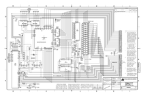
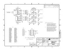
Hi-Res JPGs of Re-Designed Apple-1 Schematics

6 posts / 0 new
Last post
Offline
Last seen: 1 month 3 weeks ago
Joined: Feb 11 2021 - 05:22
Posts: 108
Hi-Res JPGs of Re-Designed Apple-1 Schematics

Hello,


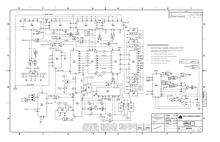
After having thought about it for a few weeks, I have decided that I will share a set of high-resolution JPGs of the re-created Apple-1 schematics with the community, so people interested can make quality prints for themselves. I will probably also make a set of them available printed on the same paper I printed the complete manuals on (Munken Pure, 150 gsm).

I hope you enjoy them as much as I have enjoyed creating them.


Best


Armin from retroplace.com


PS: If you want to get a printed copy of the re-designed manuals of the Apple-1, you can find them here.

Offline
Last seen: 4 months 3 weeks ago
Joined: Apr 9 2021 - 04:31
Posts: 90
This schematics are historic

This schematics are historic errorneous like the original ones.

If you are looking for a corrected version this one is better: http://retro.hansotten.nl/uploads/apple1/a1%20circuit.pdf

This is not a discreditiation of the great work of retroplace_1 it is just an inportant information.

Details about the error you find here: http://www.willegal.net/appleii/apple1-hardware.htm

Offline
Last seen: 1 month 4 weeks ago
Joined: Jun 5 2008 - 07:26
Posts: 475
I was going to suggest that

I was going to suggest that you make two versions - one that replicates the errors of the original schematics and a corrected version.


regards,

Mike Willegal

Offline
Last seen: 1 month 3 weeks ago
Joined: Feb 11 2021 - 05:22
Posts: 108
Mike WIllegal wrote:I was
Mike WIllegal wrote:

I was going to suggest that you make two versions - one that replicates the errors of the original schematics and a corrected version.


regards,

Mike WillegalI

I plan to issue a second version, indeed. It's just that I am not really good at electronics and probably would need help to find out which sections to change/relabel.


Offline
Last seen: 4 months 3 weeks ago
Joined: Apr 9 2021 - 04:31
Posts: 90
That's why I linked an

That's why I linked an already corrected version.

An the list of found error from Mike.

Macintosh_nik's picture
Offline
Last seen: 7 hours 22 min ago
Joined: Jan 8 2021 - 05:18
Posts: 423
Hi guys!

It turns out that the corrected version is not quite right either, a good man told me. Here's what he writes:

 
"Not to mention that the "R" and "T" signals are swapped in the drawing of the expansion connector J3. The errors are present only in the drawing on the page with the power supply schematics, in the schematic of the Computer part they are good. ACI manual is also fine. J3 drawing seems to be wrong in the corrected version of the schematic, maybe someone should notify the author of that? The correct configuration is: pin 21 --> "R" pin 11 --> "S" (unchanged) pin L --> "T" It's an error that goes unnoticed until you try to build some peripheral using that drawing as reference..."
 
Log in or register to post comments