
I have been asked by the new owners of an NTI board to restore it for possible sale next year. The board belonged to the same family that I bought mine from. They apparently had two, mine which was never uesed and this board which was. It's had many components replaced and some minor modifications made.
If there's interest I'll share updates on the restoration process in this thread over the coming weeks.
Super cool. Restoring brothers.
The bottom unit will be interesting. Looks like at some point someone shorted the transformer and blew two of the diodes. It also seems to have had other replacements. My guess is when that happened they also removed the LM323K to test it as it has been unsoldered in reinstalled witth a different screw. It also looks like some of the other regulators have been removed/reinstalled. The 5300uf was also partially removed (to test/measure it???)
There are also some caps that looked changed.
Don't forget to reform the electrolytic caps with a load (not the chips on the board to be safe). Luckily they are both NTI boards so you don't have too many Ceramic caps to "reset" to their original values, but will have to worry about which 74123 you use unless you change the resistor/cap in the RC timing circuit for the RAM refresh.
Good luck,
Cheers,
Corey
Very nice!
>If there's interest I'll share updates on the restoration process in this thread over the coming weeks.
Yes, please, go for it! :-)
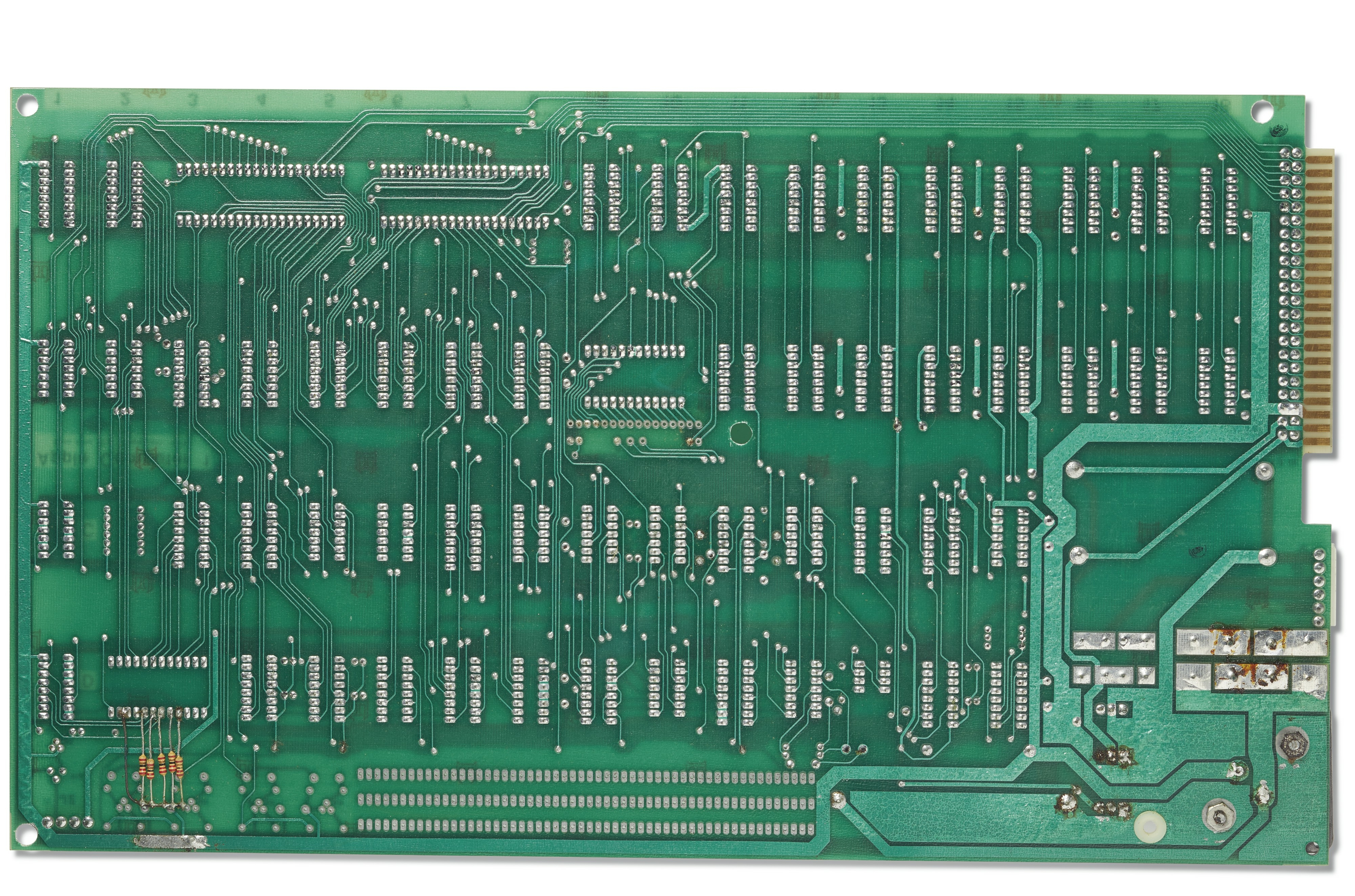
Are the 5 resistors that are attached to the back side of the CharGen IC a part of the original release, or were those added by a previous owner?
In post #3, Corey986 wrote:
"Don't forget to reform the electrolytic caps with a load (not the chips on the board to be safe)"
Methods for "reforming" may vary but you don't need a "load" to do it. Instead, disconnect one leg of the capacitor (I use the "+" leg) by desoldering and put a series resistor (~10k) in. Attach regulated DC power supply to the "+" leg via the series resistor. 0V of power supply to '-' leg of capacitor (use micro hook). Slowly increase voltage of power supply by 2V increments. Measure voltage across the series resistor and observe how it drops slowly. When it does not drop anymore but stabilizes, it's the leakage current of the capacitor at that voltage. Increase voltage on power supply by 2V. Rinse and repeat until you are at rated voltage + 10% (conservative, the capacitor manufacturer used more margin).
This mild reforming process can take several hours per 2V step, and may take more than a day. But it is safe (the rest of the circuit on the PCB sees no voltage as only the '-' leg is still connected to it) and the capacitor can't explode because of the series resistor limiting the current to a few 100 microamperes. With the original big blue Sprague 39D series capacitors there never should be a leakage current exceeding 100 microamperes so if after many hours at one given voltage the voltage across the 10K series resistor still exceeds 1V, something is wrong with that capacitor and you better don't continue. Initially, just after you increased the power supply voltage, there will be more voltage on the resistor, don't worry about this, this is regular charging of the capacitor.
If you "reform" a capacitor by brutally applying the full rated voltage with no current limit, you may get an internal thermal runaway and it may explode, spewing its nasty guts (aluminum foil shreds and toxic electrolyte) all over the place. Such an explosion might be violent enough to take an eye out. I always wear safety goggles when working with aged and suspect capacitors.
Reforming alone is not enough to declare an old electrolytic capacitor "safe". You need to do a ripple current test, too. Which requires a special test rig involving a beefy load resistor in parallel to the capacitor under test and a rectifier diode, and the whole thing being driven by the same AC voltage as seen in the regular operation of the capacitor (if in filter capacitor role). Resistor should be sized to draw the same load current as the regular load does. You observe the ripple voltage on the capacitor with an oscilloscope and any ripple that is substantially higher than the ripple observed on a known good capacitor of the same type at the same place means it's very likely not safe. To do this test properly you may need to solder some beefy enough wires to the capacitor on both of its two legs (A flimsy micro hook can't carry the current). But still, as long as the "+" leg stays disconnected from the rest of the circuit (except for the load resistor) there will be no voltage in the rest of the PCB. Note that the current peaks seen by the rectifier diode and the capacitor are much higher than the current through the load resistor (which is an average). This is why you can't use flimsy wires or alligator clips for this ripple test. The ripple test always is dangerous. I wear safety goggles and touch the capacitor during the test to see if it gets warm, and if so, immediately turn the power off. Such a capacitor is unfit for service as it will pop or explode sooner or later. It is relatively rare that this happens during the ripple test, but it does happen occasionally. I have reformed and ripple tested hundreds of quite big electrolytic capacitors over decades, and so far I was quick enough to spot the heating process and turn off the power before a bad one exploded. Sometimes they already had started to bulge despite I was quick. I don't know if it explodes, whether you would lose a finger or not. Use this procedure at your own risk only. I accept no liability for injury or death or any other incidential or consequential damages (including end of all life on the planet) if you do this. You have been warned. There is a reason why modern electrolytic capacitors have an overpressure relief of some form, such as a kerf you can sometimes see on the aluminum can. Older electrolytics don't have that feature and there have been explosions, injuries and possibly death. It's the most dangerous type of electronic component lurking in the low voltage realm.
All this procedure requires focus and no mistakes made. It's safer to take all these precious ICs out of their sockets, as Corey recommends. But this is not possible in the general case: while all original Apple-1 had sockets, there are many PCBs out there where the ICs were soldered in. But you can always disconnect one leg of the capacitor totally from the circuit and do the above work.
Despite that a proper and complete test of an electrolytic capacitor requires its ESR to be tested at full rated voltage: in the overwhelming majority of capacitors with high ESR, it can be detected at any voltage. This is because ESR has two components: the inherent energy dissipation of the dielectric, and the resistance of the conductive foils and leads. The dielectric's dissipation is greatest at low frequencies and drops at higher frequencies, while the conductors' resistance is not much sensitive to frequency. The electrolyte is an effective part of the - conductive foil, so when it dries up the resistance of that foil effectively increases.
This makes it possible to measure ESR in-circuit if the test waveform is very low voltage and very high frequency (like .5Vpp at 100,000 Hz). These parameters limit the energy lost into the rest of the circuit. The low voltage also will prevent damage to the cap from reverse voltage bias, so it can be tested in either direction despite its polarity.
The allowed ESR also depends on the capacitor's type and value, so this should be kept in mind. Large power-supply caps should have very low ESR (tens of milliohms) at 1,000 Hz, but this is not true for small electrolytics used for coupling or timing purposes, where ESR can be above 1 ohm.
Care should be taken when reforming capacitors since it is essentially an electrochemical plating process, and so can generate hydrogen gas. I believe that the rubber bung is permeable to hydrogen and so it should be facing up during the procedure and for a while afterward to let gas escape. When the foils are formed during manufacturing, they are not sealed at all.
As Uncle Bernie describes, reforming at full rated voltage (or surge voltage) will also find caps that have persistent high leakage.
As "Robespierre" has pointed out correctly in post #7 above, ESR measurements will also detect bad electrolytic capacitors.
The problem for us "hobbyists" is that almost nobody has one of those automatic LCR instruments (Wayne Kerr made a few nice ones in the 1980s which were automated by means of microprocessor, practically foolproof). So we need to improvise. The "full load ripple test" as I described in post #6 if properly done with an oscilloscope will not measure the ESR, but allows to infer if it is too high, and so far, at least for me, has never failed to identify a bad electrolytic capacitor, ever.
The key is, like the issue with the leakage current, is to have a similar capacitor of the same manufacturer and values / type, or, if this is not possible, one that is close enough, to compare. A bit fishy, of course, but if you try to look up leakage currents in the capacitor datasheets you will find out that the numbers there are useless for this purpose. They are way too high to fish out those who are on their last legs but pretend to still be somewhat functional. For instance, I've never found a Sprague 39D which had the high leakage as advertised in the datasheet. But despite the leakage current being much lower than the datasheet limit, some failed the ripple voltage test and had to be discarded.
So you need a "cohort" of capacitors, all alike, to be able to compare. I keep the capacitor data, the ripple measurement (quick sketch from the scope picture) and the leakage current (and the serial # of the PCB or assembly in question) in my laboratory logbooks. S0 whenever I pull out some old piece of equipment from my storage units or from my basement, and it acts up, I know which capacitors have been reformed and what to expect. It has been my experience that bad connectors / sockets, corroded switches or blown fuses are the most likely issues, but electrolytic capacitors come next in the row of usual suspects. Semiconductors / ICs, not so often.
If you don't need to preserve historic authenticity (a must with the priceless Apple-1 originals) it is smarter to replace all electrolytic capacitors in any well aged piece of electronic equipment as a precaution. It's not worth to replace just a few and then waste a lot of time later to search for a "dull" one. Or, if one of the aged filter capacitors explodes, have to spend all the time to clean up the mess while a change of the capacitor against a new one would only have cost a few minutes. Sometimes, however, it's too late and the mess is already there. I saw that in some old computers and instruments I restored back to life, or residues from such an event. This can really get nasty if the previous owner who did the "repair" after such an explosive event did not meticulously clean everything and so some of the aluminum pieces are still vagabonding around in the instrument.
Be careful with switchmode power supplies ... the electrolytics in them often are special types and these cannot be replaced with some random ones you may find in your parts stock. It is better to buy a new switchmode power supply instead (unless it's one that can't be found anywhere).
Remember to properly discharge the capacitors after reforming before re-soldering them.
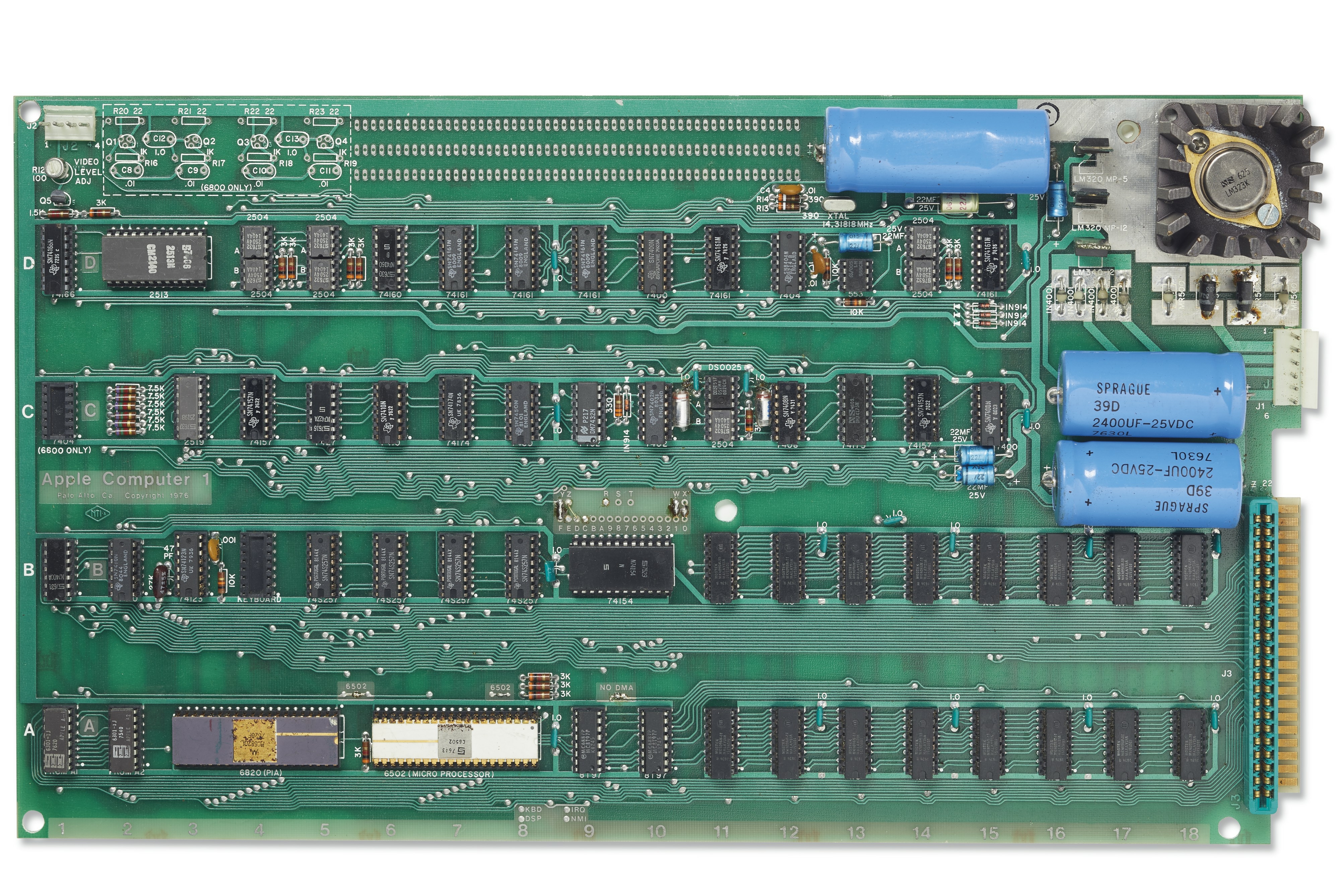
That 2513 looks suspect to me. It's got the correct markings, but they almost look fake...so it will be replaced with a known good one. The resistors were added by the previous owner, perhaps to compensate for issues with the 2513 that he used. I plan to remove them as well.
In post #10, fingerz wrote:
"That 2513 looks suspect to me. It's got the correct markings, but they almost look fake."
Uncle Bernie comments:
These markings look as if somebody made them by hand using some children's toy rubber stamp kit.
All Signetics 2513N with year 1976 date code I've ever seen had a different style of package molding form, the index indent for pin #1 on these is much larger in diameter and the same indent is between pins # 12 and #13, see here:
Real2513.JPG
The five resistors added to the outputs also give a clue that it ain't no Signetics 2513. If they go to +5V (pullup) these outputs most likely are open drain type outputs, but the 2513 has tristate outputs. So with a real 2513 you can remove these resistors.
Do you seek a Signetics 2513 with a year 1976 date code ? If so, PM me.
Before I reconfigure this board for using BASIC and an ACI, can someone tell me what the previous owners was trying to achieve here?
IMG_6065.jpeg
In post #12, fingerz asked:
".... can someone tell me what the previous owners was trying to achieve here ?"
Uncle Bernie answers:
The 4K memory block (enable: W) of $E000-$EFFF (74154 decoder: E) normally used for the BASIC interpreter was relocated to $1000-$1FFF (74154 decoder: 1). Reading the "patch board" actually is easy like that: from the 74154 decoder you have 16 signals 0....F corresponding to the 16 available 4K memory blocks. The Y, Z, R, S, T, W, X are:
Y the PROM
Z the PIA
R to the 44 pin bus, used by the ACI
S to the 44 pin bus, unused
T to the 44 pin bus, unused
W memory bank in Row A
X memory bank in Row B
If you look closely, this machine once had the usual C->R connection for the ACI card.
Hope this helps.
We have reformed the electrolytic capacitors and got the terminal section of the board running, and we will be tackling the CPU section next. The first issue we have encountered is that after clearing the screen and resetting the CPU, no keyboard input is recognized or echoed to the screen. Reset and clear screen continue to function.
I'll admit we haven't done any troubleshooting yet but figured I'd ask in case someone knows what's going on off the top of their head.
In post #14, fingerz wrote:
"Reset and clear screen continue to function."
Uncle Bernie asks:
Are you sure that RESET really works ? (You should get a prompt from the Wozmon).
But even the prompt is no proof the processor section works. If the DRAM is bad, the Wozmon typically dies and does not accept any keyboard entries. This is then often interpreted as a keyboard failure.
If you had a set of my Diagnostic PROMs (or at least the Wozmon ones with the added diagnostics page) you could quickly find out what works and what doesn't.
Not that I want to nudge you into using any of my tools, but I would be curious if they could be useful for restoring Apple-1 originals, too, and not only for building clones. Oh, and as far as I'm concerned I would not want to touch one of these priceless originals with a 10 ft pole. One small mishap and - poof - some or all the priceless ICs with the cherished date codes gone. I always wonder how folks like Corey or you have the nerves to do that. Maybe good lawyers having worked out a huuuge contract giving you full immunity. Who knows.
In any case, good luck and keep us posted on the progress.
- Uncle Bernie
I get the prompt from the Wozmon and then nothing accept the flashing @ symbol. I'll check the DRAM and will contact you about your Diagnostic PROMs
In terms of nerves I think if you're careful about the power supply section of the board, not physically damaging the board, or inserting any ICs upside down, then most of the other possible mistakes are fixable. Even if a period-correct IC is damaged, which happens, you don't begin a project like this without having some spares. Even though some are hard to find, given enough patience and the willingness to spend some money almost anything can be sourced.
Apple-1 Restoration - 29 December 2021.jpeg
Progress update...things are going reasonably well. I have some replacement components that I've ordered that I expect to recieve next week (yellow), repairs (green) are done and tested, and red are the components that I'm still trying to source. The issue with the keyboard input turned out to be a faulty 74123, however there may still be an issue with the DRAM as sometimes I see characters on the screen change a few seconds after being drawn. I will try and figure that out tomorrow. I haven't run any memory tests or tried to load BASIC yet...baby steps.
It's running! Mostly. I wouldn't describe it as being 100% stable, but I'm going to stress test it after the weekend and see what lingering gremlins there may be. Wishing all of you a Happy New Years!
71566337-BE90-4DE2-9987-2DCE15DD72F1.jpeg
After running the checkout program for 15-20 minutes continuously, characters start to shift and other visual glitches start to appear. As more time passes, the frequency of these glitches increases until eventually (another 5-10 minutes) the display freezes. I'm not sure if the CPU has locked up or not, or whether the heat related issues are limited to the Terminal section. If I reset the CPU and run the test again, the glitching starts almost right away and the display freezes again after 3-5 minutes.
Video of the issue:
https://youtu.be/m14c73eAmaQ
Hi fingerz. Did you try to replace one of these shift register 2504 (1404)? Looks like one has an intermittent failure when getting warm. I got a similar issue (Exclamation marks all over the screen) when I burned in my system. I also see some exclamation marks showing up in your video.
I understood these 1404 IC's are failing very often. So I ordered a bunch from Hong Kong (Ebayer "newton-computer").
If you wait for UncleBernie he will probably point you to the exact chip ;-)
... this looks like a bad 1k x 1 shift register to me. The 2519 is less likely to cause that (would be a new trick for a bad 2519).
Cold Spray is a wonderful invention to find the culprit. But I'd not dismiss the good 'ol 'scope to see if the suspect 1404 have good TTL level swings at their data outputs. Those 46 years old carbon compositon resistors can be a bitch. Bad contacts in a socket, too.
Do not fumble with some ESD protection stuff for the cold spray. Just spray it on the suspect ICs. If you use small amounts / short squirts there will be no significant condensation from the humidity in the air. If you get water droplets after the cold spray you have overdone it. Just wait until the ICs are dry again.
You could also try to identify the bad 1404 by inspecting which ASCII codes flip to which other ASCII codes. Comparing the bit pattern will point to the bad bit(s) which corresponds to one (or more) 1404. Just read the schematic. Swapping the suspect 1404 against another one would move the bad bit. This would prove the culprit is that IC.
The 74157 muxes are less likely the culprit as the errors seen are not static. Bad 74157 tend to wipe out a bit permanently.
If it happens to be the 2519, however unlikely, I have plenty with date code 7627.
Only if the 1404 and the 2519 can be ruled out, we would need to look elsewhere.
The Signetics 2504 are troublesome. I avoid them for my kits as about 30% ... 50% I had in hand were duds right out of their original manufacturer tubes. I've seen this with various date codes from 1975 and 1976. With more than 1000 AM1404 I only had two or three duds. There is a difference whether the wafer fab is being run like a pig pen or like a real clean room. It's tempting to use simple products like those shift registers as "pipe cleaners" after a major mishap has shut down the fab.
After such a mishap they always use "pipe cleaner" products to bring the fab back on line. This might explain why the Signetics 2504 are so bad. They were the simplest PMOS products they had at the time.
And while we are at it, I found that the 2519N with date codes from 1977 are also junk. About 25% I had in hand were bad despite they were new old stock (Manoshewitz in Jerusalem sits on 5000+ of them). Most of the bad ones I encountered were duds right out of tube. But about 1/4 if the 25% bad ones died during the first few days of burn-in. This sucks. With the 2519B date code 76XX I had only about 1% bad ones so far but I'm still screening them.
The Signetics 2513N character generators so far were OK. Only 1% bad ones.
Comments invited !
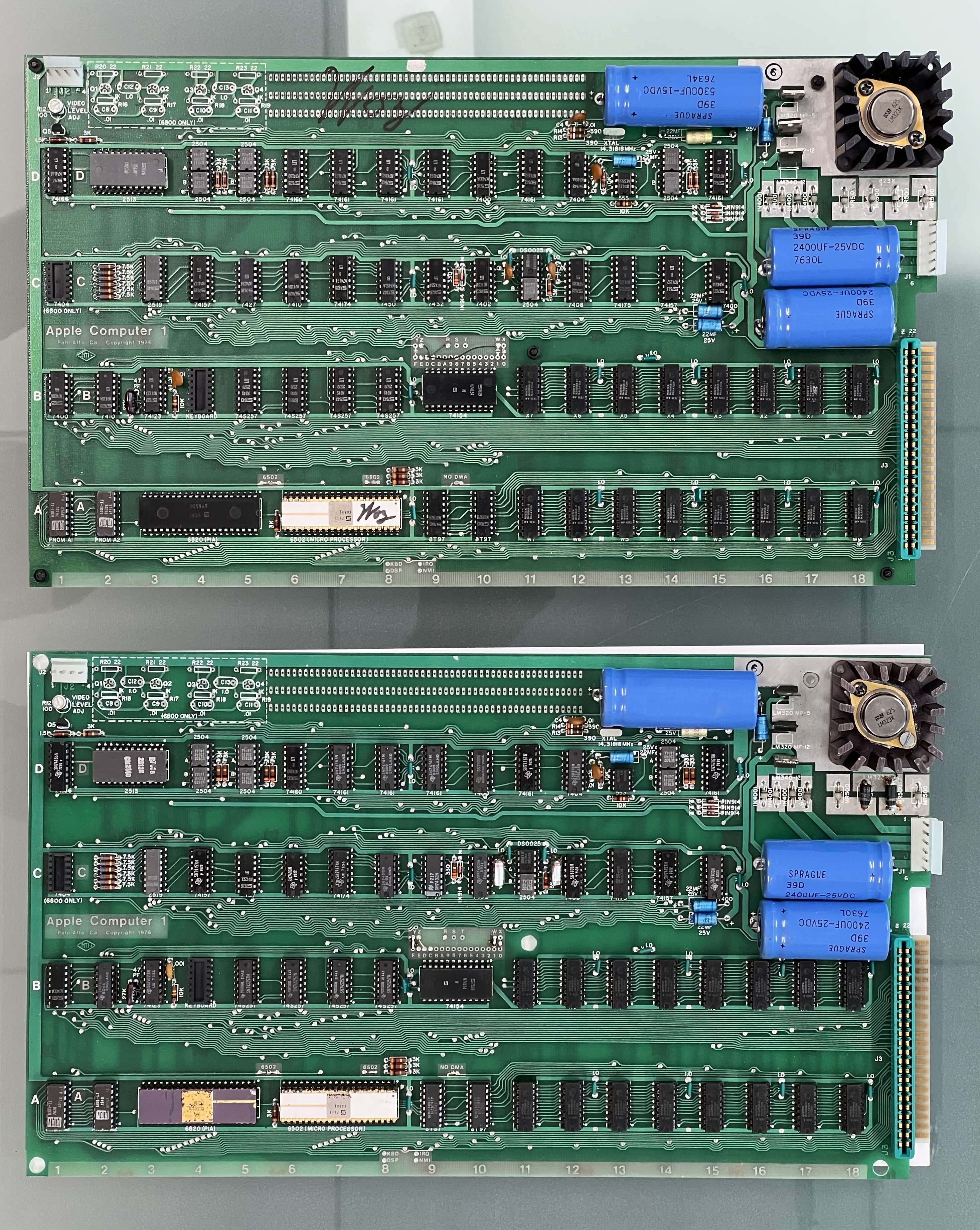
Turns out the problem exhibited by the shift registers was due to the DS0025. We suspected that early on, but the replacement didn't help. On a whim we tried a third one after exhausting all other options and that did the trick.
The board is now running well even after four hours of continuous operation. We ended up replacing 31 components, removing 4 resistors that had been added by the previous owner, and reflowing a few solder joints. All of the replacement components are period-correct and are the correct Signetics parts for an NTI board...except the 74S257's which are TI parts from 1977. I was unable to find 1976/1975 Signetics versions of these.
1B44C39F-A4DE-4058-A943-971507F64163.jpeg
4CE8DC1E-56CC-462B-9B92-5F4B6480CD4B.jpeg
6A303D02-CF01-4CBD-96E0-8AA65AF559E4.jpeg
This is how the board is now post restoration. I'm proud of the work we've done, but if anyone sees any additional that could be made let me know. Actually, I still need to make time to go to the hardware store and find the correct machine screws for the heatsink...I'll try and do that this weekend.
89 Schlumberger Apple-1 FRONT.jpg
89 Schlumberger Apple-1 BACK.jpg
Well done! ... and thanks for posting those hires photos too.
Question: Do you plan to touch up the trace to the back side of the board at location D-3? (E-3 if it were marked...)
Translucent Green paint is available and can be masked and sprayed/blended to cover it up fairly well.
Reference: https://www.ebay.com/itm/113385076489
I'm pretty sure that's a manufacturing defect present on quite a few boards so I will leave it as it is.
I'm planning to mount the board on a wooden base. Here is the layout I have come up with so far. Any suggestions for improvement of the layout?
Apple-1 wooden base board design.jpg
Apple-1 wooden base board design 2.jpg
In post #27, fingerz wrote:
"Any suggestions for improvement of the layout ?"
Uncle Bernie answers:
I think the fan is not needed in such an "open" configuration. I have seven Apple-1 clones running 24/7, open boards, never a problem with overheating.
Being a fan-less "silent" computer is an essential feature of the original Apple-1 experience. Same for the Apple II. Put a fan in and it's not the same user experience.
I think Steve Jobs would agree if he was still among us. He always wanted the "zen" of silent computers.
From a practical standpoint, I think mounting an Apple-1 with a keyboard on the same base in which the keyboard does not obscure parts of the motherboard, leads to an unwieldy solution. It depends of course for which purpose the finished machine will serve. For a display in a museum you would need to protect it from curious fingers by adding some translucent enclusure and your layout would be fine, allowing patrons to see the whole thing.
One member of this forum (macintosh_nik) has a more compact layout with a detached keyboard. If wear and tear on the original keyboard connector is a concern, add a keyboard connector on the base plate into which the cable from the detached keyboard plugs, so the original connector on the motherboard is not being stressed.
- Uncle Bernie
Adding a fan because Steve Jobs' "zen" keeps overheating is an Apple tradition that spans decades.
The Apple 1 was designed by Steve Wozniak, not Steve Jobs. Woz was the engineer and he would know by design that the Apple 1 5V section needed a fan.
Past examples of discolored boards under the 5V regulator makes obviouss. My vote is you keep the fan and preserve the board. The 2 Steves had that argument in past. Personally I get it, having a nice quiet computer is preferred, but I think the Apple 1 goes a bit outside of that by design. Analog 5V supplies need cooling annd everyone knows it.
Here is a SUGGESTION of how I would lay it out, keeping the electrical cord in the rear. The scale of the switch & pilot are not accurate but you get the idea. Be sure to leave enough room for the add-on board connector and board space.
Apple-1 wooden base board design.jpg
In post #30, macnoyd wrote:
"Analog 5V supplies need cooling annd everyone knows it."
Uncle Bernie's point of view is different:
Macnoyd probably meant "linear 5V supplies" (vs. switchmode 5V supplies). An "analog supply" would be something which feeds analog circuitry. Different requirements / specs. Let's be more precise with naming subsystems, please. Beginners may get confused and what not. The regulators in the Apple-1 are "linear regulators". They stabilize the output voltage by making the voltage difference between the unregulated input voltage and the regulated output voltage disappear ... into heat. Actually, if we want to be precise, the excess power (said voltage difference multiplied by the current) turns into heat.
You can calculate this. A typical Apple-1 draws 1.5 A on the +5V side. On the 5300uF filter capacitor you typically have +11V (which is a lot more than the LM323K needs). The voltage difference is 6V. Times 1.5A is 9 Watts. Which are converted to heat. A typical finned heat sink of that type has a natural thermal resistance of about 5 Kelvin per Watt. So in a convection style air flow situation, expect a temperature increase over ambient air by 9 Watts x 5 Kelvin / Watt = 45 Kelvin. Which if the room temperature is 22 deg C (72 deg Fahrenheit, sweating !) means the heat sink will stabilize at 22 + 45 = 67 deg C. This is well within the commercial temperature range of 0 ... 70C and an absolute nothingburger for the LM323K (die temperature is a little bit higher, the die to package thermal resistance is also there).
If you don't believe my math, take a thermometer to your Apple-1. You will see no more than 45 Kelvin increase over room temperature. If the heat sink was properly mounted, using the right nuts and bolts, with the right torque, and thermal grease with no voids.
OK, my math is rule of thumb. I could show you the actual voltage as measured by an oscilloscope and write down the nasty integral equations. And I could show you the whole thermodynamic model. But for what purpose ? The rule-of-thumb math above is good enough. There is no danger. The heat sink on the LM323K is adequate for convection cooling. If you increase the air flow by means of a fan you can get the thermal resistance down to half of that.
The real problem with the Apple-1 regulators is the +12V regulator which runs at a waaaaay to high input voltage and closer to its thermal limit where it would shut down to protect itself. But still, I never needed a fan to mitigate that. (Do not touch the metal tab of the 7812 - you will get a blister).
As to Woz being an engineer, his Apple-1 power supply design would not have made it through any design review in the industry. They would have sent him back to the drawing board. Or, if his boss were a psychopath, they would have fired him. But for his defense, I can see how it may have came about to run those regulators at input voltages being way too high. When Woz designed his computer (before it became named the Apple-1) he may have had only those particular transformers (and filter capacitors) at hand (in his lab junk bin ?). Which worked. With no problems whatsoever. And then, after they had founded Apple Computer Company, and Steve Jobs had reeled in that $50000 order from BYTE SHOP, there simply was no time left to revisit the power supply to optimize it. It could be done. Just reduce the transformer output voltages and reduce the filter capacitors, and save a lot of money, and avoid a lot of heat and a lot of costs.
But still, there are no thermal issues with the Apple-1 power supply as specified in the Apple-1 manual. Yes, it is very, very inefficient. But still far from any device limits. You can easily run a typical 7812 at +125C tab temperature. The built-in thermal shutdown to protect the device from thermal runaway (pass transistor SOA) kicks in at far higher temperatures you can never reach in an Apple-1.
Now, the deterioration of the PCB material of $1 million originals due to the elevated temperatures is another topic. But rather than adding that nasty and loud fan, I'd specify a transformer having a lower output voltage, and be happy. As a rule of thumb, the positive linear regulators of that family need only 2.5V minimum voltage differential when trying to start up from -55 deg Celsius. But be aware that you need to look at the input voltage with an oscilloscope - the "valleys" are the limit. Once the system runs, the heat generated will increase the die temperature and the required voltage differential drops even further. BTW, satellites and probes in outer space have a small Plutonium-240 heat source installed to allow the start up of their electronics after being powered down for prolonged periods of time. No issue for earthbound Apple-1, though.
Conclusion.
You don't need a fan on the Apple-1. Period. If you want to preserve one of the priceless originals, don't power it up. The ICs will die from a multitude of deterioration mechanisms long before the heat will make the PCB material crumble.
This is the final layout that I settled on for the board and other components. The only thing left to do is make some wooden wedges to mount the keyboard.
CF50DD5C-BDFB-44E1-A429-48B140F01C77.jpeg
Any plans for sides & cover?
No plans for any cover, that will be up to the future owner to figure out. My limited experiences with acrylic have not turned out well so I'm avoiding going down that path. If you have suggestions for a design that would work well please let m know.
For now this is the finished product and it's basically the best I'm able to do.
_DSC0437.jpg
Schlumberger Apple-1 image 1.jpeg
50A6F0BA-F2AB-4149-B454-D4FA24A137D5.jpeg
B85A1CBE-E1CC-4420-BCD8-A7333F3441B6.jpeg
True work of art. Thanks for sharing!
Looks sweet!