I have almost completed my Apple Computer A including the Datanetics keyboard and case. This is my 3rd build with the last two using Uncle Bernies Kits and Mike Newton boards. Both are working great! The Apple A is also from Mike and Uncle Bernie and is working minus the upper DRAM bank not "talking" yet. It will run Uncle Bernies Prom pin 14 Dram test and WOZ's test program.
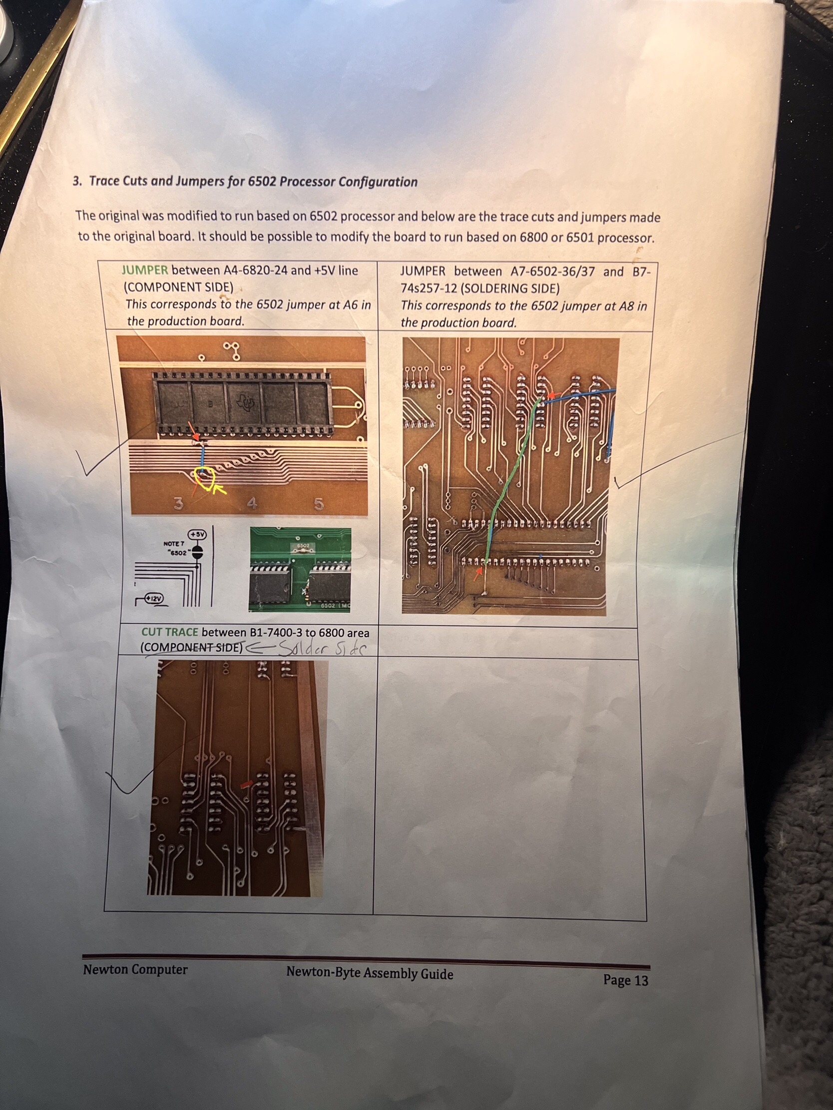
On page 13, of Newton-Byte's Apple Computer A Prototype Assembly Guide, I believe I found a mistake. If the JUMPER between A4-6820-24 and +5V line is soldered to the second VIA, as pictured in the assembly guide, the computer will not work. It will put 5v plus the clock on CPU pins 36/37, PIA pins 25, makes B7 warmer than its neighbors and makes the computer "dumb" with only the CLR working. Looking at the pictures of the original/broken prototype, I finally noticed that the +5V is in the first VIA not the second.
When the JUMPER is cut and or moved the Prototype is working!
Is this an error in the Assembly Guide or have I missed something?
You are correct, +5V should be fed to pin 24 of PIA and that's the first via hole for 6502 to work. I haven't updated the guideline after I corrected that in my own prototype board. Thanks for bringing up.