Hi All,
I'm stumped with this power supply. Hopefully someone can help me out.
Symptoms
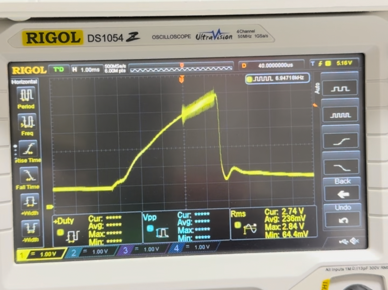
When I power it on underload, it makes a 6khz buzzing sound. It sounds similar to the noise made when you plug in a working power supply without a load, but the click is 10x~20x faster. Here is the waveform that is generated when plugged in under load:
The Power Supply
When I bought this power supply, a couple of the parts were pulled off/missing. Specifically, the main power transistor, the power switch, and the cable grommet.
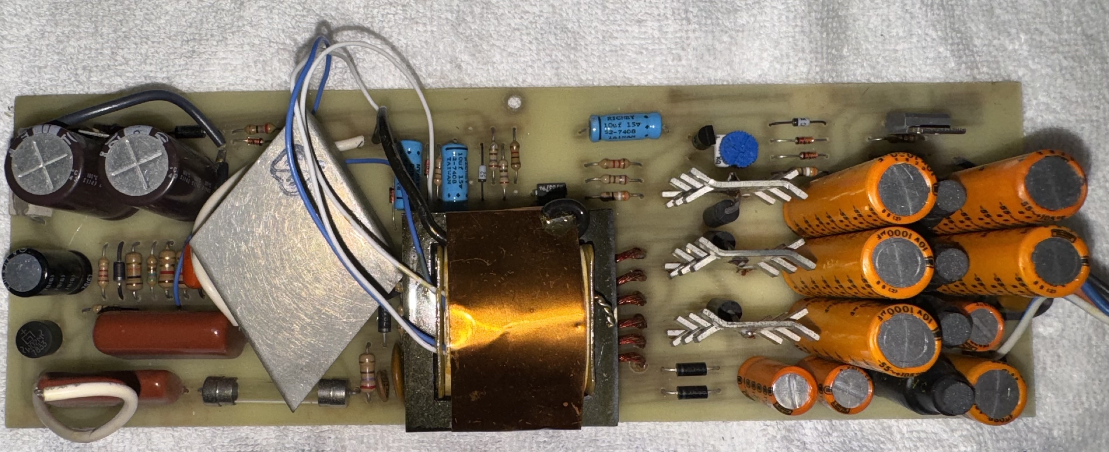
One of the first things I did was replace all the capacitors with high quality nichicon replacements
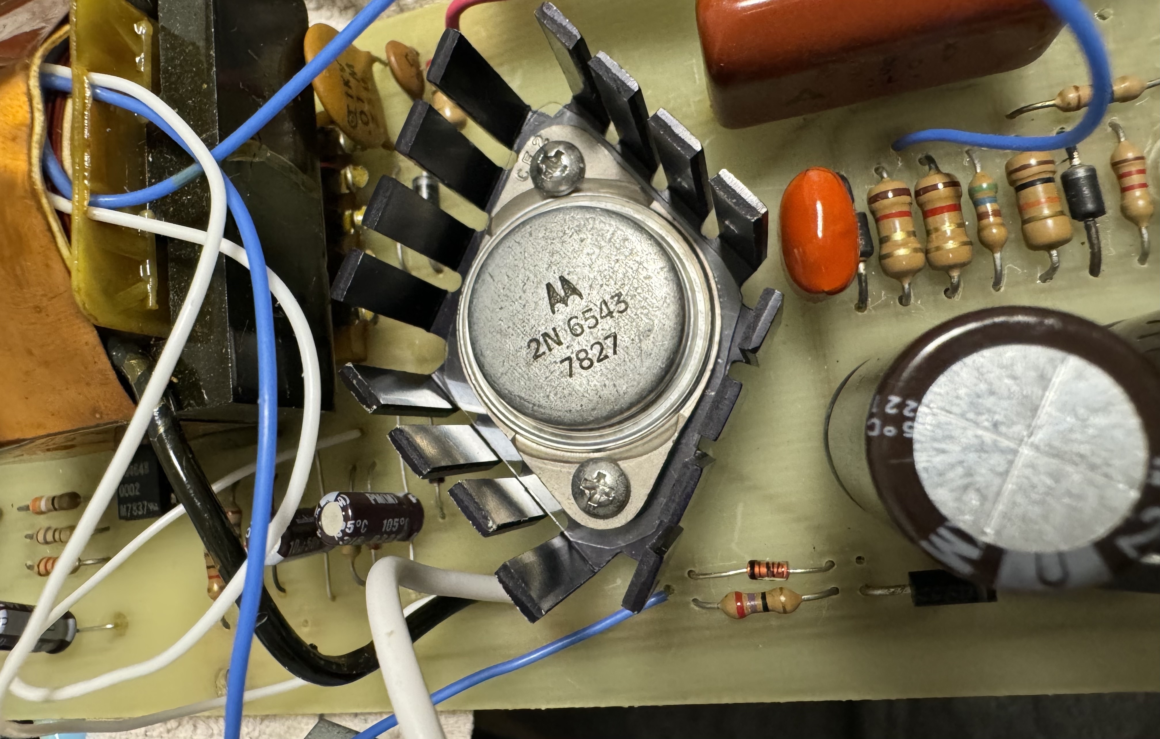
I also got a replacement power transistor and put it in (yes, I did put in the cover afterwards and connected the wire that goes to the cover):
Troubleshooting
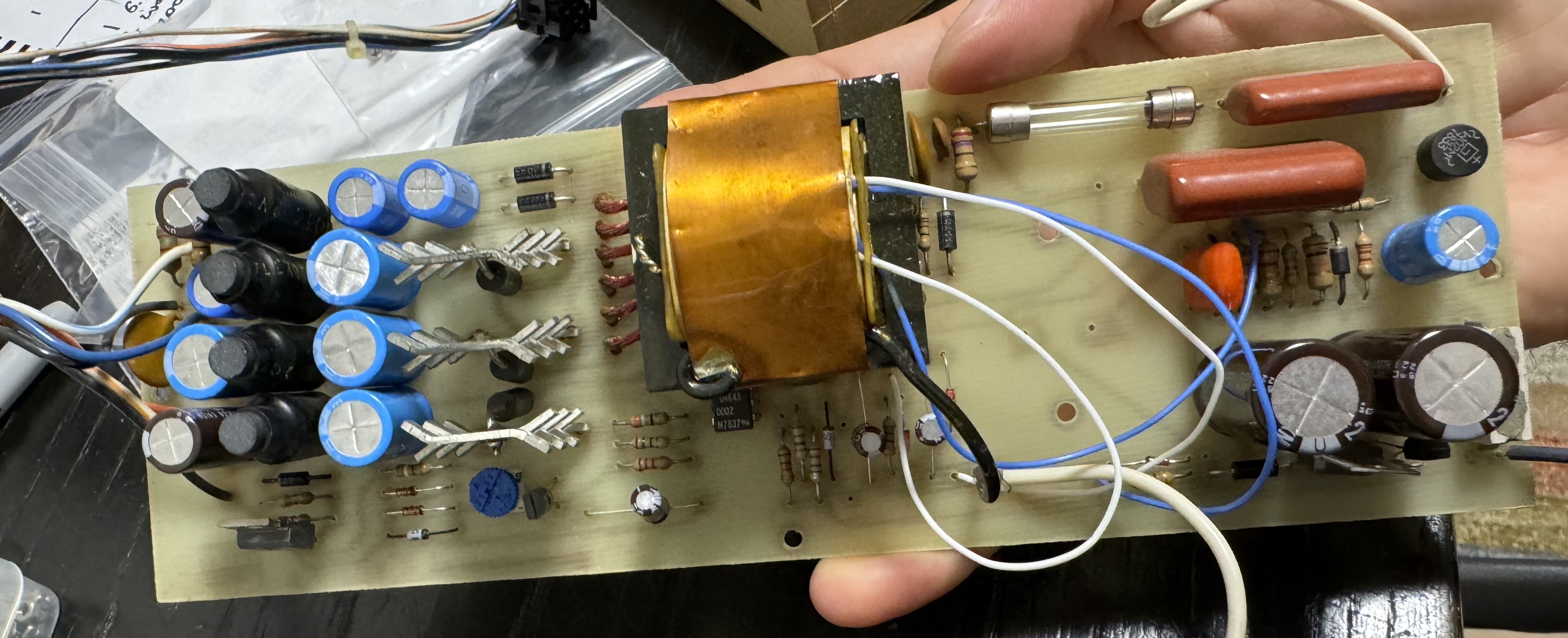
I have a second working power supply with the same design (layout is a bit different, but all components are the same). I re-capped both of these at the same time with same capacitors. I went though and compared all the capacitors.
- I checked the value of every resistor against the 2nd working power supply, all are the same.
- I checked the diodes and transistors using Diode Test mode on my multimeter (in both directions) and complared between the two power supplies, all values are the same.
- I checked for shorts in all capacitors, none found
- I compared the resistance and diote test values for the IC on the two power supplies, they are the same
- I check power transformer for shorts, the transformer between the two power supplies match exactly
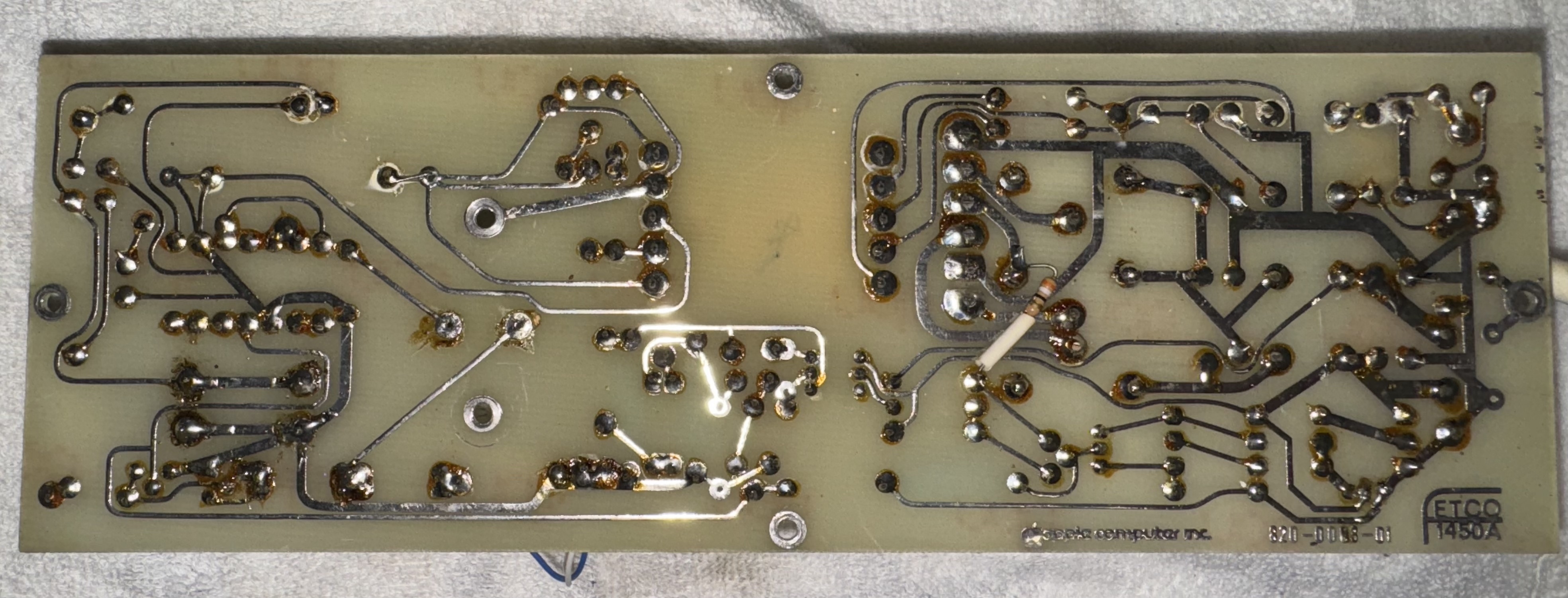
- I washed the bottom of the board and double check for any shorts.
If helpful, I can post a video of the sound it makes when plugged in.
Only noticable difference between my 2 power supplies is the one that works has 2x 100uf 200v capacitors, while the non-working one has 2x 220uf 200v capacitors.
You said you replaced caps with "high quality" ones. If you did not replace them with high quality low ESR caps then it may be a problem.
Leakage is the main problem with caps in switching PSUs, not shorts.
The two 220uF/200v caps are twice the capacity as the originals and could change switching timing. I'd have to look at my schematic to say for sure. I recently re-cap'd my Apple II Rev 0 supply and made sure to use 100uF/200v low ESR replacements.
Definitely the problem is not the caps in this situation, if they are brand new. None of them need to be low ESR. It just helps with longevity, since they run cooler and the longevity is also a function of the temperature. You can even put crappy cheap caps, as long as they are new and not defective, the PSU will run fine for few years. That being said, you should always check the capacitance and ESR of new caps before soldering them, no matter how expensive they are.
Also if the original caps were of certain capacitance, there is no reason to change it when recapping. So if they were 200uF originally, keep the new ones the same value.
What I would do instead is start comparing the oscillograms from the SAMS books.
I always try to pick the lowest ESR and longest life Nichicon caps. I doubt this would be the issue, as the other PS works fine with the same caps.
Note that I replaced them with the same as the originals. The originals on the earlier Rev board use 220uf and the originals on the later rev board use 100uf.
There is a chance that maybe the 220uf aren't actually originals. Maybe someone years ago ran into a problem and tried to replace original 100uf with 220uf (that's all they had laying around?). I see a couple other same revs boards do use 100uf, seen here and here. Let me try this next.
Unfortunatelly the SAMs book I did find for the power supply is for a later revision, which is quite a bit different.
If 100uf instead of 220uf caps don't work, I'll move on see if maybe replacing the octopcupler helps.
@andydiags, could you let us know what resistive loads you are placing on the +5V and +12V supplies?
In the 2nd "here" post references you made, the 2nd one had my load spec that worked well of:
"I made a +5v and +12v load resistor set providing a 4.6 ohm load for +5v and 34.2 ohm load for +12v."
The +5V load should be above 500mA if I remember correctly.
I've been using a 2 channel load tester. It however died on my this week. Since I know the power supply doesn't jump over on voltage (and I might get scolded for this), I'm using an actual Apple II as the power load right now. I don't turn it on for more than 2 seconds at a time.
Couple updates on the progress (or non-progress), using LaserMaster's diagram for reference.
CamBam+ A2M001-3615-PCB-ComponentSide_0.jpg
Looking at the pics of the bottom of my board, it does look a bit like C1 and C2 may have been replaced in the past. I pulled the 220uf's and put in 100uf 200v into the non-working board, this unfortunately didn't solve the issue.
I also tried to replace Q2 and Q5 from my working board; this also didn't help.
Next up, I'll try to replace AR1, Q1, and Q4. If that doesn't work, I'll need to go back and triple check all the components using a multi-meter.
A question and an observation:
Question: Where was the scope probe connected in your first photo, and the image is too small to read much of the stats on the scope display? If I squinted it looked like the peak-to-peak volatage on the waveform was like 2.4v or so. Could you post an image with much higher resolution?
Rather than replace AR1, you should be able to test the diode and the opto-transistor in place.
It would be helpful to know what the resistive load in Ohms your were using on +5 and +12v outputs in order to determine voltagle and current delivered to the loads.
If you are having to use the Apple II to load these two supplies, with the PSU disconnected from the motherboard, you should get the actual resistance from the motherboard's power connector's +5v pin and GND and then the +12V pin and GND, in order to determine they are enough loading to satisfy the PSU outputs on these voltages.
Check out pages 21, 22 and 23 of "W. Gayler - The Apple II Circuit Description" on how this PSU works.
The probe is connected to one of the IC chips on the Apple II. Here's a video of the waveform: https://youtu.be/ACeOQanNPIw
I already did the diode test on the opto-transistor and it passed. But I also tested out every other component in place and they all look fine. My guess is that one of the transistors or diodes may have gone out of spec and misbehaves under load. I replaced the opto-transistor last night, board still doesn't work.
I'll go back and review the book, thanks.
Now that you have an almost identical working PSU you don't need a SAMS book. Plug them in side-by-side and you have an oscillogram at every single point.
Fixed! Ended up being Q1, the 2N3904 transistor. Replaced it and it boots perfectly now! Thanks for the help everyone.
IMG_3839.jpg