A few tests for a non-booting Disk II controller
I confess that my disk controller stopped booting after I installed another shrouded header, but investigation led me to a simple cause and an absurdly-low-tech solution: bambooIn the process of diagnosing it, I contrived a handful of techniques to gather data about the fault:
- Monitor commands to verify 6 of the 8 latches in the 9334 or LS259 chip. (failed)
- Monitor commands to verify operation of the LS323, LS174, and both 6309 or LS471 chips. (passed)
- Makeshift test to individually verify electrical signals from latches Q0 through Q3. (Q0 Q2 Q3 passed, Q1 failed)
- Using a flashlight for "candling" of circuit traces. (fault located)
- Using a bamboo skewer to remove debris from circuit traces. (fault cleared)
Monitor Commands to verify 6 of the 8 latches in the 9334 chip
The following procedure verifies correct operation of 6 of the 8 latches in the 9334 chip. If the test passes, then latches Q0 through Q5 are all working properly. If the test fails, then it won't pinpoint a specific cause -- it will merely indicate that there's a fault somewhere that prevented the test from passing.This test uses FloppyEmu as a diagnostic tool, attached as Drive 1.
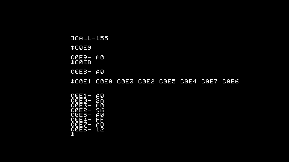
- Test Q4: In the monitor, type C0E9 <return> to start the disk drive. If Q4 is working, FloppyEmu should turn on its green disk-activity LED, and the word "READ" should appear on its display.
- Test Q5: In the monitor, type C0EB <return> to switch to Drive 2. If Q5 is working, FloppyEmu should turn off its green disk-activity LED, and the word "Read" should disappear. If Drive 2 is attached, it will switch on.
- Test Q0-Q3: In the monitor, type C0E9 C0EA <return> to start the disk drive and switch back to Drive 1. FloppyEmu should turn on its green disk-activity LED and the word "Read" should appear on its display. It should also read "Track 00".
Note: If you initially interrupted booting by pressing RESET after you turned on the computer, it might cause the following test to fail on the first attempt.
- Increment the track number with the command C0E1 C0E0 C0E3 C0E2 C0E5 C0E4 C0E7 C0E6 <return>. If latches Q0 through Q3 are working, FloppyEmu will increment to "Track 02".
Monitor Commands to verify operation of LS323, LS174, and both 6309 chips
The following commands verify correct operation of FloppyEmu and several other chips on the disk controller. This requries latch Q4 to be working in the 9334 chip.
- On FloppyEmu, select a bootable disk image.
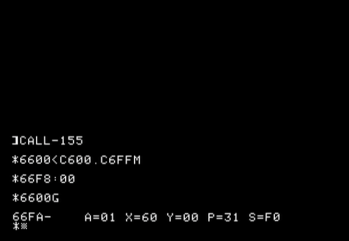
- In the monitor, type the command 6600<C600.C6FFM <return> to copy the bootstrap firmware into RAM.
- Type 66F8:00 <return> to insert a breakpoint into RAM copy of the bootstrap firmware.
- Type 6600G <return> to run the RAM copy of the bootstrap firmware. FloppyEmu should show its green disk-activity LED and the words "Read" and "Track 00" on its display. If the computer beeps and displays "66FA-" followed by assorted register values, then the LS323, LS174, and both 6309 chips are all working correctly. If it doesn't respond, then there's an indeterminate fault somewhere.
Test individual electrical signals from latchs Q0 through Q3
The following test uses the disk cable and an LED to test individual data latches Q0 through Q3.
- With the computer turned off, connect one end of a disk-drive ribbon cable to the disk controller, and disconnect the other end from its disk drive or FloppyEmu to expose its female header.
- Test Q0: Insert an ordinary LED into the pair of holes corresponding to positions 1 and 2. Turn on the computer so that the controller tries to boot from the floppy drive. If Q0 is working, the LED should flash rapidly for 2 seconds and then go out. If the LED doesn't flash, reverse the polarity of the LED and repeat the test. If it still doesn't flash when trying to boot, Q0 might be faulty.
- Test Q1: Same procedure, but this time insert the LED into holes 3 and 4. If Q1 is working, the LED should flash rapidly for 2 seconds while trying to boot. If you try the LED in both polarity orientations and it still doesn't flash, Q1 might be faulty.
- Test Q2: Same procedure, but this time insert the LED into holes 5 and 6. If Q2 is working, the LED should flash rapidly for 2 seconds while trying to boot. If you try the LED in both polarity orientations and it still doesn't flash, Q2 might be faulty.
- Test Q3: Same procedure, but this time insert the LED into holes 7 and 8. If Q3 is working, the LED should flash rapidly for 2 seconds while trying to boot. If you try the LED in both polarity orientations and it still doesn't flash, Q3 might be faulty.
Use a flashlight for "candling" of circuit traces
Shine a bright flashlight through the circuit board from the reverse side, move the light around, look for unexpected shadows or bridges between circuits.
Use a bamboo skewer to remove debris from circuit board
If you find (or suspect) any stray debris, solder splash, or metal whiskers, use a wooden dowel or bamboo skewer to scrape them away.
- S.Elliott's blog
- Log in or register to post comments


