

| Attachment | Size |
|---|---|
 2026-05-31-09-56-24-518.jpg 2026-05-31-09-56-24-518.jpg | 2.78 MB |
| 2026-05-31-09-56-44-222.jpg | 3.01 MB |

Hi everyone. After a few days, I’m back again to talk about the Applied Engineering RamFactor. I’m still looking for the piggyback module to expand it to 4MB of RAM, but today’s issue is a different one.
I’ve bought, received, and installed a compatible battery—specifically this one: https://www.pilebatterie.it/index.php?controller=search&s=MUMP3-8+. I powered on the RamCharger using +110V through my step-down transformer. The green “battery ok” LED comes on, the yellow “Backup” LED comes on, and when I switch it on, the green “AC ON” LED also lights up. Fortunately, nothing exploded and there was no magic smoke from burnt components.
Now I’m left with a doubt. I’m starting from the assumption that I’m totally ignorant when it comes to electronics, so before making mistakes I think twice and try to gather all the information I can. I need to rebuild the 4‑pin connector that links the RamCharger to the RamFactor. I need the correct pinout—the more detailed, the better. Please assume you’re dealing with a complete beginner.
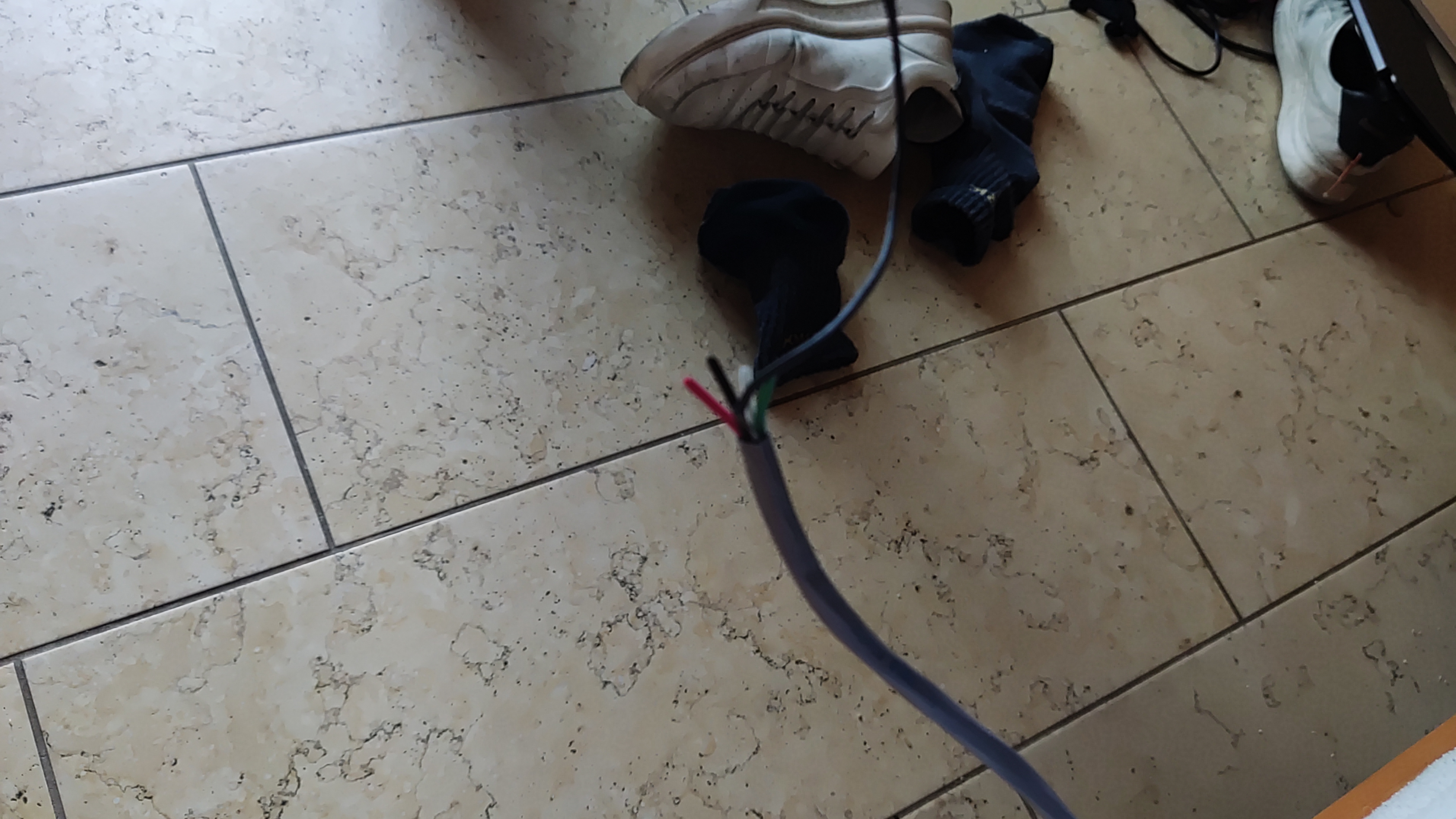
From the RamCharger I get 5 wires: 2 black wires, which are surely ground, one red wire, one white wire, and finally one green wire. The black wires surely need to be connected together, I think. Can you help me with the exact pin assignment from left to right for the 4‑pin connector on the front of the RamFactor?
Thanks in advance to anyone who can help.
delete please
delete please
Does this help?
Screenshot 2026-05-31 at 07-05-56 Macintosh Apple II Applied Engineer Ram Factor Ramcharger Memory Expansion Card #1799891304.png