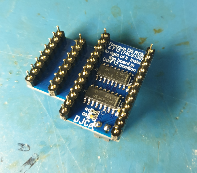
Hi all,I built an SMD Apple ROM replacement board for Apple ][, ][ plus and ][ europlus.NOTE : This is not a new design - well I've substituted in the 39SF010A flash chip (most use a 27c256 eprom), but the overall concept has been around a while. This is the first SMD one I've seen though, and certainly the most compact!This board replaces all 6 ROMs on the motherboard - you can leave most of the original ones in the sockets as it will overide them - install the board by removing the D0 ROM plus the 74LS138 to the right of it (position F12), then plug this board into the vacated sockets. It takes up no more space that the outline of the 2 sockets it plugs into.
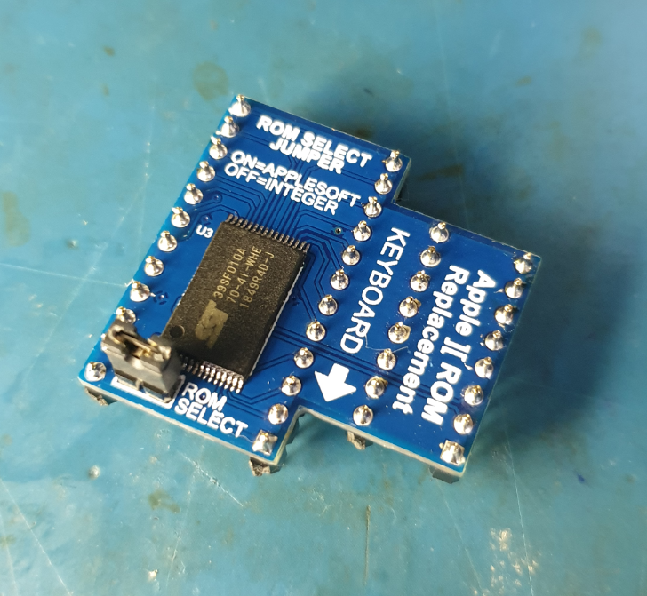
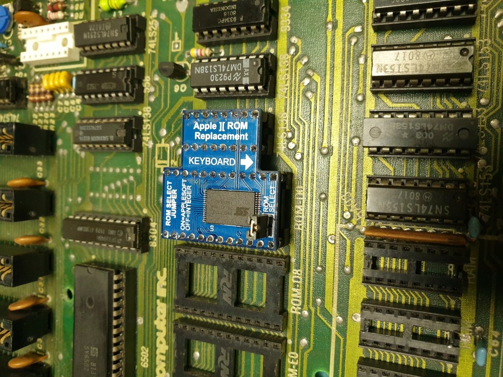
There is a jumper that allows you to select from 2 different sets of ROMS - Applesoft Basic with Autostart F8 ROM (as per the Apple ][ plus, ][ europlus), or Integer Basic with the non-autostart F8 ROM as per the original Apple ][. If you have a Language Card with the Autostart F8 ROM on it, that will take over from the onboard ROM as per normal.With the Integer Basic ROM set I've included the Programmers Aid ROM.The ROMs used :APPLESOFT D0 - 341-0011APPLESOFT D8 - 341-0012APPLESOFT E0 - 341-0013APPLESOFT E8 - 341-0014APPLESOFT F0 - 341-0015APPLESOFT F8 - 341-0020 AUTOSTART MONITORINTEGER D0 - 341-0016-00 PROGRAMMERS AIDINTEGER E0 - 341-0001-00INTEGER E8 - 341-0002-00INTEGER F0 - 341-0003-00INTEGER F8 - 341-0004-00 NON-AUTOSTARTThis is a handy board to have when troubleshooting a system as you now have a set of known good ROMs - especially given the pin rot that some of the original 40 year old ROMs seem to get (the legs get very fragile and can snap off easily - originals are a 9316 masked ROM and are expensive to replace - original masked ROM sets seem to fetch high prices on eBay).It also allows you to remove all your originals and put them in safe keeping!Here it is installed :
Cheers,
Dean
Hi Dean,I would like to understand if your object can be of help to diagnose my problem with an Apple II Europlus (see my latest posts).If so, where can I buy it and how much does it cost with economic shipping to Italy?
I'd buy one if it used IC pin header instead of machine pins. Those will ruin the motherboard sockets.
I wanted to know if the SMD Apple ROM is compatible with the 16K Language Card
Correct - they are too big - especially for the vintage AMP/RN sockets used. Worse still, they were supposed to be 0.5mm but turned out to be 0.6mm! 0.5mm is still way too big for these sockets - I'm looking at 0.4mm headers ATM.
Yeah - the language card F8 ROM will override the one on the flash chip as per normal behaviour (the slot inhibit line disables the flash chip as per it would with the regular ROMs).
This is a fantastic addition to Apple ][ hardware. I want one!
I would like to see a few things added / changed if this is still in the development stage.
1. Can the board be made green to match the Apple ][ motherboard color?
2. Can you add or change the select jumper to a 3-way surface mount slide switch, which would give 3 ROM set choices?
3. Can these be sold as a kit? (I know, not many can solder SMD's that small)
4. (long-shot) Can the boards be made colorless? (some say off-white)
Do you plan to release the artwork so we can make our own?
Comment: It's OK to use round pins IMHO because the connection is better, but I understand how it spreads the socket pins.
I'd probably buy two. Let us know when you have a workable, finished product available.
Nice work.
I was hoping that someone might one day clone the Apple ROM card, but this seems a better option, as it won't eat up slot 0.
P.S. Is it flashable, with custom images? That'd be a rather hot feature, but I don't see any sort of interface on it. Perhaps something to consider for Mk II. one other thing, if you ever update the design, it'd be wise to position the ROM select jumper to where it is in-between slots. A long card would potentially bump into that 2-pin header.
I advise using a right-angled ROM-select header for the production boards. Most people will likely put that on an external switch.
One more suggestion... (gotta have yet one more, right? ;-) )
Fill the Integer D8 position with "The Inspector" ROM. It's a handy utility to have, especially with the AutoStart ROM turned off.
"Dr. Watson" takes up the D0 position, which is also the same address as the Programmer's Aid, so you'd need a 3rd choice for that. :-)
This all makes me curious how hard it would be to use a soft-switch to bank different ROM contents into memory, perhaps using I/O reads from the keyboard; or to select which ROMset you want via a menu or a hotkey on startup. Sort of OT, but an interesting notion.
This would itself need to be a routine in-ROM, though, or at least stored in memory via a custom ROM and may be a bit of an issue. In theory, you would need to load the custom ROM, which then selects the desired set and overwrites itself. That last part seems like it'd be rather tricky and probably error-prone, unless you have a 64K machine, as you could jump to a routine in a higher address range, have it load the desired set, then jump back; but clearing the memory used for this routine probably wouldn't be easy; it could be overwritten, but I don't think it can be safely zero'd after loading the ROM images and executing the jump to start them.
File under: Would be nice
One more suggestion... (gotta have yet one more, right? ;-) )
Fill the Integer D8 position with "The Inspector" ROM. It's a handy utility to have, especially with the AutoStart ROM turned off.
"Dr. Watson" takes up the D0 position, which is also the same address as the Programmer's Aid, so you'd need a 3rd choice for that. :-)
Thanks - that is awesome feedback!! To answer your questions (and start some further discussion on features) :
1. Yes I can do green soldermask. Blue soldermask is kind of my thing, but I agree that on an Apple ][ motherboard it stands out like dogs balls! Green (or possibly Black) would blend in better.
2. This is slightly tricky because I used a jumper rather than a switch intentionally - so that an external switch could be added easily. However this is a 1mbit ROM with a couple of unused address lines - if I add a second jumper you can have 4 ROM sets selectable. a 3rd jumper would give you 8 ROM sets selectable, buts that's probably getting silly. This will lead on to your last question which I'll come to shortly :)
3. Yes they could be sold as a kit - with a preprogrammed flash chip for those who are either a) experienced at soldering or b) want to be experienced at soldering :) Its not hard - the tsop is a 0.5mm pitch, however once its tacked down you can just drag solder each side - takes a few seconds plus a few more to remove any bridges (you need good flux for this - I recommend BGA gel flux). The 74LS138s are the same - easier because of the increased lead pitch so you tend to get less bridging but you could also solder them pin by pin. The resistors and capacitors are 0603 - small but not crazy small.
4. I'm not planning to release the gerbers just yet - let me get the additional features on there and I'll review that again :) I understand international shipping is expensive - especially if the assembled PCB is AUD $20-$25 or so, and the shipping is half again or more. Some sort of group buy would help with that though - I could get a LOT of them in a small box with tracked international shipping.
Ok - back to the ROMs. When I built this I decided to ground the unused address pins as I thought that by including Applesoft ROMs, plus the Integer ROMS (including programers aid) I'd have covered off everything (excluding J plus - thats a differnet kettle of fish due to character set etc).
BUT you have opened my eyes to these other ROM's that I've kind of heard of but know nothing about. Custom programmability is a little bit of a pain due to the wiring of this thing (spanning 2 sockets) - I program the flash chips before soldering them down (using a 14mm tsop32 -dip32 adapter) and have pulled the Write Enable line high on the PCB. To make them re-programmable is possible but I'd have to add a zero ohm resistor or jumper to unlock the WE line, plus some custom programming adapter socket board to adapt the pinout to a 32pin DIP for programming in an eprom programmer. Basically a lot of additional mucking around for something that probably not a lot of people would use? I will take a look at it though and have a bit more of a think about it. If I add the additional ROM slots though, and we get the ROM contents right, then there probably wont be much demand for custom contents. Is that fair?
Im very keen to discuss the ROM contents that youd like to see - lets work on 4 different sets for the moment - I'll add a second jumper to make this happen.
Timelord wrote:
P.S. Is it flashable, with custom images? That'd be a rather hot feature, but I don't see any sort of interface on it. Perhaps something to consider for Mk II. one other thing, if you ever update the design, it'd be wise to position the ROM select jumper to where it is in-between slots. A long card would potentially bump into that 2-pin header.
I advise using a right-angled ROM-select header for the production boards. Most people will likely put that on an external switch.
Thanks Timelord - some more great feedback there. Yes the right angle in headers is a great idea - this board is very low profile so a right angle header should clear any long expansion cards etc. Great point.
In regard to the programmability - please see above - I'll have a bit more of a thing about it - it would require another PCB as a programming adapter at minimum but also likely some additional components on the main PCB to jumper the programming function. If I get the ROM's right then 99% would probably be satisified and the 1% that want custom could potentially remove the flash chip and install another?? Anyway I'll think about it some more.
Thanks again guys for your feedback and suggestions!
This is a good idea that has been going around for a while...
I have seen several versions of this flash ROM solution. The common problem (which this version seems to have solved) is that due to the extra height, most peripheral cards on slots 5,6 or 7 will not have enough clearance. Also the typical pins that are found are too thick for the motherboard sockets.
For one of my Apple II's, I build a ROM adaptor with 4 banks. It has 3 used banks as follows:
Bank 0: Applesoft
Bank 1: Integer BASIC with Programmer's Aid ($D000) and Inspector Watson ($D800)
Bank 2: Wozanium pack (Apple-1 emulation)
Bank 3: available
This card is intalled permanently directly on the motherboard without sockets so it presents a low vertical profile. (see pic below)
A more flexible and practical solution is to use the "BrainBoard" card developed by Mike Willegal, which has the same functionality as these adaptors and will work with or without the original ROMs installed and the banks can be selected with soft switches or the on-board DIP switches.
I have extra blank PCB's for these projects, PM me if interested.
IMG_6259.jpg
IMG_6187.JPG
Ok - I can add programmability using a custom programming adapter - I've updated my schematic but haven't updated the board yet - possibly might have to grow the PCB a little bit - I'll see. I think I can get away by adding just a jumper or zero ohm resistor.
In regard to the pin issue I'm using either 0.4mm thick pins (which should be fine) or 0.25mm thick pins (which will absolutely be fine but may be a PITA to work with). Slot clearance shouldn't be an issue with right angle jumpers (which I could move to the other side of the PCB if I have to but I think will be fine as is - will confirm on my test mule tonight :) ) The flash chip is less than 1mm thick!
That Brain Board is a Slot 0 ROM card, right?
I'd be interested in some PCBs.
Yes, The BB card goes on slot 0 on a II or II+.
Details are on Mike's website www.willegal.net
Another idea I have seen used to keep component height low for connectors, is to edge mount them.
You have to pick the right thickness of PCB, but if your spacing is just right you can clip a pin header onto solder headers on the edge of the board and solder them to each other. Not only do you get less height, but you automagically get a "right angle" connector effect.
(Visible on the DB9 connector here, as an example.)
It's a bit of stuffing around to set it up in Ki / Eagle, but it's a neat effect to bring Z height down.
Chesh
Thanks - I've taken than on for the new board. Has 8 ROM images selectable and is re-programmable via a DIP32 adapter in an eprom programmer :)
Still cleaning it up but it will look like this pretty much :
2020-05-20_16-58-29.png
+1 on that one Dean.
You could go even further by using a tiny header size rather than the 0.1" spacing header. But you've got the right idea here.
A couple other switch considerations if using 4 ROM selections... These are all very low profile and allow you to preset the board.
https://www.ebay.com/itm/153454427834
https://www.ebay.com/itm/264622385530
https://www.ebay.com/itm/163474931367
Using a set of flat pads like that saves pennies, and helps to promote damage later in the product life, whereas through-hole right-angle connectors will be almost the same height profile and are more stable. If you are having these boards assembled in China/SE Asia, that overlapping part might also be a problem for their automation processes.
Apple firmware cards and Brain Boards (which are modified derivatives of the Apple firmware card) work in any slot and you can put several in the system. If they are placed adjacent to each other, when selected they will disable lower priority boards using the Apple II bus's DMA in and out signals. If I remember correctly, higher numbered slots have priority.
Mike Willegal
I did consider the 1.27mm pith and 2.0mm pitch headers, but figured that 2.54 is easier for people to make up an IDC cable at home and connect to a switch board. (for external switching).
The low profile keeps it well out the way - even though most people will have a short Disk ][ Interface card in slot 6 (which would come nowhere near it) - configuring the jumper like this keeps it nice and low - I'll use the jumpers with the little tail piece on them to make then a little easier to remove/place however the way to go is an external switch (which is why I havent put SMD switches on the PCB).
Manufacturing wise, I'll be hand soldering these - I doubt I'd sell more than 50 all up so not bothered - I consider myself to be pretty decent at soldering. At work we have a pick and place and reflow oven, but for the first batch I'm just going to totally hand assemble.
As far as strength goes, the 6 quite large SMD pads are very strong - I used the same setup for the Pseudo DB-19 on my Switcheroo! (https://forums.overclockers.com.au/posts/18486491/) - I should have posted a thread here for that one too!
This is where I'm at - does the legend make sense? There are 8 banks 000 through 111 (eg.010 = bank 2, 110 = bank 6) - jumper on is a 1, off is a 0 :
REV0.png
I keep flip flopping between ROM Sets and ROM Banks on the legend - I guess all the same in the end. Now I need to get some input on the ROM sets that people would be most interested in putting on there so I can build a ROM image.
I have some ROM sets that I will send you shortly.
I would like to buy some boards from you that are the colorless (some say white) boards if I can.
I'm willing to buy a small batch. Also some green boards. Minimum batch size for both.
Let me know on that. In the mean-time, I'll collect the ROM sets and send you the descriptions.
Rev0 Green.png
A work of art :-)
My PCB order has been submitted - green soldermask. I'll test this one out, and then perhaps do another run in another colour. I did add slightly to the legend - added a small "4 + 2 + 1" directly above the 3 jumpers to help with the math when working out the rom set number :)
Oh - J1 is a 0402 resistor pad - I'll just bridge it with solder, and its easily removed for programming (solderwick).
Anyways - time to build some ROM images !
Hi Dean,
congratulations on your work.I like this forum, where you can get to know artists like you or iwg1962, with its retro style Apple IIe Diagnostic ROM Card
See your PM. I can send others if you are looking for more. (I've got a pretty good collection. )
I've designed and ordered some programming adapters - got these in white mask, black silk just because I haven't done any boards in that colour before :)
The adapter allows the SMD ROM Replacement to be programmed in an EPROM programmer. I *might* use one, though I have a tsop adapter. Be handy for reflashing though while getting the ROM image sorted. Ultimately not many people would probably need one, so long as the ROM images loaded cover off most of the bases.
White PCB.png
Colour wise, they should look like this :
White.png
Bob, can you share the contents of the ROM images that you are proposing?
Be clear to the company producing the boards that your client wants no colour for the PDB, as there is such a thing as white PCBs. Those are a shiny white, not the old 1970s colourless PCBs, that he wants.
Check your mailbox. (ROMS sent)
Also, TimeLord is correct. (directly above) There is a difference from colorless and white.
Colorless is preferred, but you are the person creating and ordering, so it's your call.
I want you to know that this project is an awesome contribution, regardless.
I am willing to fund the colorless version AND the green version if you want. Just let me know.
Couldn't the EEPROM be programmed in circuit? Granted not everybody would use it but that would make it much easier to re-program. Shouldn't be too hard to write the programming software.
And the switch board - using the same ALPS switches I use on my Switcheroo! PCB :
romx.png
I even have a name for it now - lol - probably not too original, but neither was Switcheroo! :)
I'm pretty sure the colour PCB you guys are talking about is a transparent solder mask with black FR4, and white legend. OSHpark offer that as an After Dark board (https://pbs.twimg.com/media/ECDpXR0UYAE_PqH.jpg)
The transparent mask does look pretty cool . I'm thinking about putting all 3 of my boards together on a small panel like I did for Switcheroo! and Pseudo DB-19 - be nice to do it in the clear.
These boards have been ordered. I have the ROM sets from Bob, and will start created some initial ROM sets that I can flash on, along with a quick reference sheet with the ROM set numbers and descriptions :)
I was just going to put three toggle switches on perf and wire them up on jumper lead wire/ribbon. :D
It is easy to build a shell for toggle switches, so that I can put it on the side of the unit with no fear of shorting.
Yeah - for the price of the PCB though, I thought it would save a lot of mucking around and I can just stick rubber feet under it or 3D print an enclosure :)
I'll look at getting one of these babies: https://au.mouser.com/ProductDetail/Grayhill/94HBB08T?qs=ls7QRyWmRk67N6Qq31S%252BcA%3D%3D
(I'm a rotary dial fan, so sue me! :-)
That would work pretty well - its pretty small though? I could look at implementing one of those - ideally something a little bigger (that one is only 1cm x 1cm approx).
Rom sets so far :
0 = Applesoft Basic1 = Integer Basic with Programmers Aid @ D0, empty D8 socket, no autostart 2= Integer Basic with Dr Watson @ D8 / The Inspector @ D0, no autostart3= ??4= ??5= ??6= Applesoft Basic modified for lower case7= Apple 1 Emulation
Any other suggestions to fill slots 3,4,5? Or a preferred order?
1. Integer BASIC + AutoStart ROM.
Would populating D8 with the autostart ROM still work with this design? I'd still think that having AutoStart available for both AppleSoft and Integer BASIC is prudent.
2. Diagnostics ROMs:
I cannot stress enough how useful it is to have a ROM-based diagnostics tool. Here's the Apple set, although perhaps something better exists now.
https://mirrors.apple2.org.za/ftp.apple.asimov.net/emulators/rom_images/077-0022%20077-0023%20Apple%20Diagnostic%20Card%20-%20ROMs%202764.zip
3. Apple ][ J-Plus
The J-Plus uses a very specific ROMset to allow Kana characters to function, and I would think that this board would appeal to people in Japan who may want to convert a standard ][+ to a J-Plus.
https://mirrors.apple2.org.za/ftp.apple.asimov.net/emulators/rom_images/Apple%20IIj%2B%20ROMs.zip
Changes:- the monitor REGDSP (display registers) routine has been removed- the RDKEY main loop has been modified to flash an underline cursor- the RDKEY main loop now checks for ctrl-T to toggle katakana output
Notes:- all changes are in the F8 ROM- REGDSP was removed solely to make room for the new underscore cursor code- the RESET handler already asserts the annunciator states on RESET (no change)- katakana output toggling is handled by the inverse mask byte at $32
Some other things worth considering:
https://mirrors.apple2.org.za/ftp.apple.asimov.net/emulators/rom_images/Research-A%20modified%20F8%20ROM%20%28CTRL-RESET%20and%20%27-%27%20goto%20monitor%29%2C%20Screen%20Address%20Calculator%2C%20Cassette%20Port%20AD%20Converter.zip
Something else to consider, although it'd be for a future revision, is a simple jumper to select the AutoStart ROM to be installed with any set. (This may conflict with some, but it could reduce the overhead of needing duplicate sets just to enable AutoStart.)
awesome thanks - yeah the applesoft rom set would include the F8 Autostart ROM, but if you have a language card then that has the autostart anyway and would override the flash rom as per normal. It will also override the non-autostart rom in the integer rom set - youd have to remove the language card to experience non-autostart.
Diagnostics sounds like an excellent idea - I'll definately include that - which ROM address should they be installed - F8/F0?
Jplus - yeah - I think you need the japanese character generator (correct me if I'm wrong), but yes - handy for people who have a J Plus.
Thanks - that's amost a full set now :D
What about the people who want autstart, who don't have an Apple language card (only a 16K card), but who want Integer BASIC by default?
Can you not map autostart to the Integer BASIC ROMset as an option?
OBD would make this a killer app upgrade. I'm unsure how they are mapped, but I can hunt about for details if no-one else here knows.
Ah yes - good idea - autostart f8 with integer set. Do I create 2 of these - one with dr watson and inspector, one with programmers aid? There would be 4 integer sets of I did that, 2 applesoft, apple 1, and a diagnostics - 8 sets.
I would cast a vote in favor of that combination.
Too bad we can't have separate F8 ROMS in the mix. (now I'm REALLY starting trouble! <grin>)
That's a great starting point anyway, and fills the 8 slots. I can start there and if anything else come up can revise.
I've been able to locate manuals for both Watson and The Inspector ROMs (thanks Michael and Paul for helping me track down the Inspector manual!) and have realised that I had them assigned to the wrong address locations. Inspector is installed at D8, whilst Watson goes at D0.
An integer basic ROM set with the Programmers Aid at D0 can also have Inspector at D8 (this will be one configuration I'll go with).
The starting point :
0 = Applesoft Basic - autostart F81 = Integer Basic with Programmers Aid @ D0, The Inspector @ D8, non-autostart F82= Integer Basic with Watson @ D0 / The Inspector @ D0, non-autostart F83 = Integer Basic with Programmers Aid @ D0, The Inspector @ D8, autostart F84= Integer Basic with Watson @ D0 / The Inspector @ D0, autostart F85= Diagnostics ROMs (I need to work these out - there are two ROMS - F8 and F0 I assume)6= Applesoft Basic modified for lower case (requires replacement character ROM as well)7= Apple 1 Emulation (Woznium Pack)
Does anyone know anything about the diagnostic ROMs? I'll assume they go in at F8, F0 but perhaps they are designed to replace D8 D0 in an integer basic system, which might make more sense?
Dean, where did the Diagnostics ROMs come from?
I've been searching for info regarding Apple ][ " Diagnostics ROMs" but find very little on it.
Can you share the code? I'd like to give it a look-see. Maybe I can tell you more.
Hi Bob,
Hmmmm - yes - I think they are actually IIe ROMs looking at the size. Bugger. Are there diagnostic ROM's of some sort for a II/II+? That would be very nice to include. I thought I saw a reference to Apple II dead test ROM's somewhere - will see if I can find it.
Also I wonder what other ROM's were created back in the 80's to install in D0/D8 positions in an integer basic system - like the Watson/Inspector combination created by Omega Microware.
I have a collection I will review tonight, but The Inspecor / Dr. Watson ROMS were premiere EPROMs back in the early Apple ][ / Integer basic days.
The documentation was well written and therer was a nice load of utilities, with or without a Disk ][, though a lot was geared around the Disk ][.
Programmer's aid was also a good DOOO ROM choice. It was dependent upon your needs.
My opinion, but the Dr. Watson chip became more a choice of the Program Cracking community, whereas the Programmers Aid was more for Software Developers.
I have a collection of "Fourth" EPROMS and a few other F8 EPROMS, but I don't see those as really useful as the others you have on the list.
Stuff like that, we can load to the language card.
I don't know that there was ever a ROM code in the DOOO-FFFF memory space for the Apple ][ or ][ plus that performed diagnostics. Not that it can't be put there, but I do know of some diagnostic code that was made for the ROMPlus board that occupies the COOO - CFFF memory space. Not sure you want to go there. The possibilities are there if you want to. Happy to share it if interested.
I certainly hope we can find some sort of diagnostics to the A][, A][+ as I have a very unhappy one that if I could get diagnostics working without having to have any other cards in would make me very very happy :-)
Pages