Transmitting a simple datagram via Video Vapor
For every horizontal line of video the Apple transmits, the video scanner consumes exactly 65 clock cycles to access exactly 64 bytes of memory. (One of those 64 bytes is accessed twice during HBL, consuming one extra cycle.) Therefore, if I take those previously-contructed memory-access maps and cross-reference them against the schematics in the Apple II Reference Manual, we can organize the video scanner's memory accesses into eight 8-byte "octets" whose contents are being streamed onto the data bus like a DMA stream:
- Each line of visible screen memory is scanned/streamed in five octets, always accessed sequentially while transmitting the visible part of the signal, for a total of 40 contiguous bytes accessed in 40 clock cycles. So, just by accessing memory to trransmit a video signal, the video scanner accesses (and thus refreshes) 120-of-128 rows of a 16K DRAM chip, or 240-of-256 rows of a 64K DRAM chip.
- During HBL there are 24 invisible bytes being scanned/streamed in three octets, which are accessed in 25 clock cycles. This is when the video scanner is obligated to access the so-called "screen holes" (aka: "hidden 8") which contain the rows of DRAM that were missed while transmitting a video signal.
So, mentally organize video memory in this simpler scheme -- as 5 visible octets and 3 invisible octets. Imagine sampling the visible stream of data. If the data stream from visible memory is sampled at 8-cycle intervals, we will obtain exactly 1 sample from each of those 5 octets. Now let's pack some data into those octets to meet the following criteria:
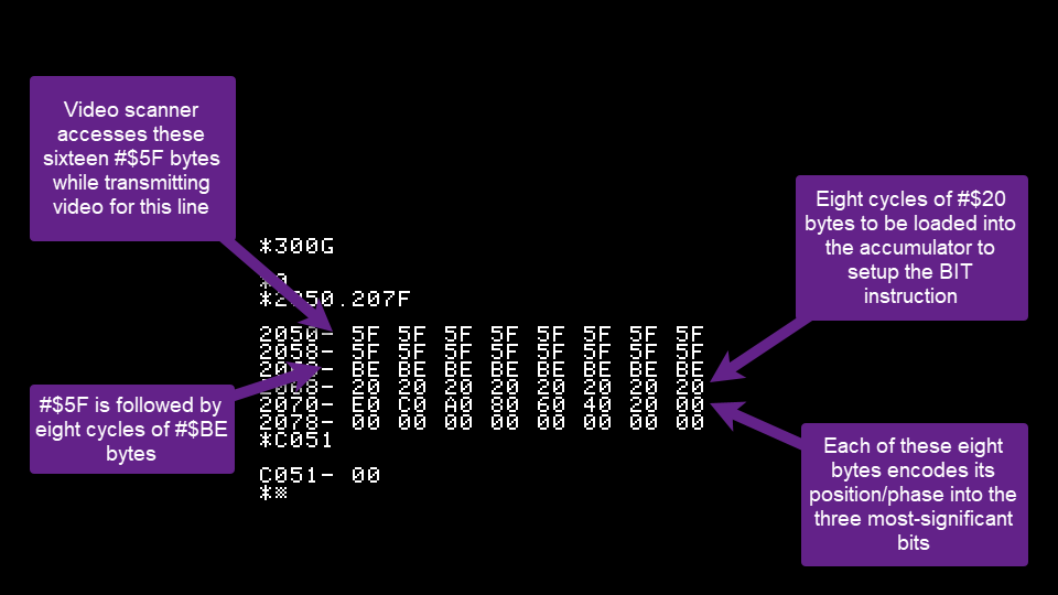
- The first 2 octects contain a recognizable start-of-line indication, for which I've arbitrarily chosen $5F. A vapor-reading routine can use this to detect that the video scanner has begun transmitting a line that contains a data payload. By filling 2 octets with this code, we allow 16 cycles for the vapor-reading routine to react to that start-of-line signal.
- The next octet contains a recognizably-distinct value to notify the sampling routine when the scanner has gotten past the start-of-line signal and can transition into reading a meaningful message from the data stream. I chose the byte $BE because it can be loaded into the accumulator in just two clock cycles by using an ASL instruction to transform the value $5F that was used in the previous step. ($5F is binary 01011111, which ASL shifts-left into $BE or binary 10111110)
- The next octet contains $20, a single bit which will be loaded into the accumulator for use n the interpretation of the data payload in the last octet. There isn't time to verify its exact value at this stage due to the tight cycle counts, but it can be checked later (if desired) because the accumulator will be preserved from here onward.
- The final octet contains eight distinct values, assigning a unique value to each byte that identifies its position within that octet. This is our data payload, the "message" that we've transmitted via one row of video memory: a single-cycle-accurate indicator of the video scanner's timing.
Now to try it out!
Let's build a routine to build our datagram in video memory. Based on video scanner memory maps, lines 64-191 each start with two octets of memory that are accessed only while the video scanner is transmitting them, so let's start our datagram at $2050, the left edge of line 128.
That routine worked on the first try -- it filled memory at $2050 with the desired pattern of bytes.
Somehow, it just feels "wrong" that it worked "right" on the first try!
Next, add a routine to sample the vapor stream and read the datagram when it detects it.
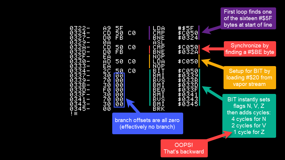
The routine loads $5F into the accumulator and compares it to vapor by reading the graphics-mode soft switch at $C050. This IO address's only documented purpose is to switch-on graphics mode when accessed, so it doesn't return any IO data. Since there's no IO data from that address, the processor instead receives the last byte that the video scanner accessed on the data bus.
Upon matching the value $5F, meticulous cycle-counting ensures the rest of the data is read at exactly 8-cycle intervals so that the processor reads 1 byte from each of octet of visible memory. The routine samples for $BE to ensure it has passed the start marker, reads $20 into the accumulator, and executes a BIT instruction against a byte in the last octet to set the N, V, and Z flags in the 6502's status register.
Finally, it calibrates itself to the video scanner's timing by executing seven strategically-chosen non-branching branch instructions. All branch-offsets are 00, so the branches themselves don't affect the instruction pointer, but they do affect processor timing. Each branch instruction adds 1 cycle if the specified condition (N, V, or Z flag) is met because the 6502 requires 1 extra cycle to add the branch offset to the instruction pointer.
Once again, it seemed to work on the first try.
But I couldn't really be sure because my routine doesn't do anything to demonstrate whether it really received the datagram, nor does it demonstrate whether it really syncrhonized its timing to the video scanner. Not yet, anyhow.
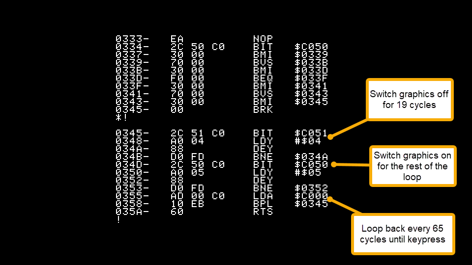
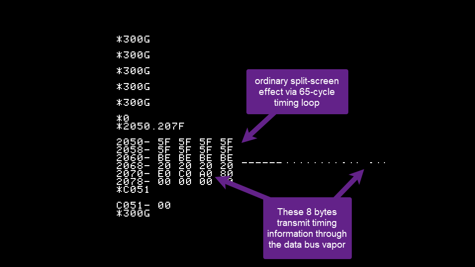
Okay, let's add a simple 65-cycle screen splitting routine to demonstrate whether the routine is correctly synchronizing itself with the video scanner. At this stage we merely want to verify that it synchronizes itself in the same way each time it is run, so don't worry about where the screen will be split.
And it works on the first try! It displays 18 columns of text, then hires graphics.
And it works on the second try! It display 18 columns of text, then hires graphics.
And it almost works on the third try...except it displayed 20 columns of text, then hires graphics. So it's not quite working.
I tested ten times and made a tally. Five times the screen displayed 18 columns of text, and five times it displayed 20 columns of text.
That's a rougly 50/50 split, suggesting a bug in the lowest bit.
Aha! The logic of the Z flag is opposite to the others: when that particular bit is set in the vapor stream, the Z flag is cleared.
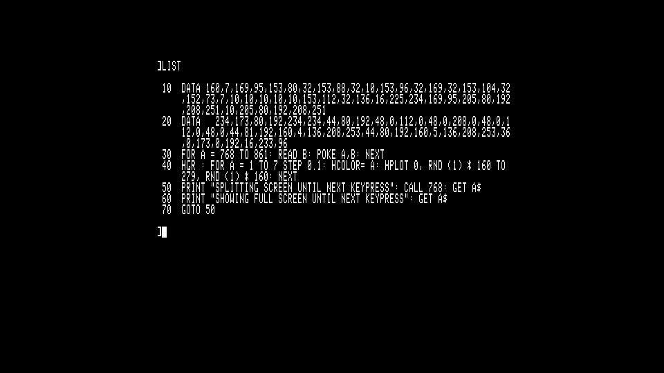
Let's incorporate that into a BASIC program to allow more rigorous testing. I embedded the machine code into DATA statements, drew some arbitrary graphics, and added PRINT statements to prompt the user to toggle between split-screen and full-screen modes.
And now it really does work consistently. Every time the routine is called, it splits the screen at exactly the same column.
It's really nothing new to use vaporlock to split the video screen, as documented in previous blogposts like Side-by-side graphics/text windows and in the 'instrument selection' feature in ACHUS software based multi-voice synthesizer.
But the screen-splitting routine confirms that we really did transmit a datagram through the video vapor channel, and it confirms that the datagram could pass 3 bits of phase-information via the 6502's status flags, and it confirms that the 6502's status flags could adjust execution timing by 0-7 cycles with single-cycle accuracy.
All those attributes are required for my next project, to devise a unified platform-independent routine for reading the status of the Apple's four video soft-switches. Hopefully, a software-only retrofit to add the Apple //e's ports $C01A~$C01D to an Apple ][ or Apple ][ Plus, a novel method of using those addresses to read those bits of data correctly...consistently across Apple ][, //e, or //c.
- S.Elliott's blog
- Log in or register to post comments


