This is a picture of my SE/40et. SE/30 + Asante network card + right angle PDS adapter + Daystar IIsi adapter + 40 Mhz Turbo 040 card:

I have a couple more pics in my image gallery.
In this shot I’ve got my Rasterops 264 SE/30 color video card held next to the left side of the chassis to show that there is enough room for this card to fit inside the case:

Using a diagram from Gamba’s site, I edited it to show my configuration as well as the missing piece to make it work together. Given that the open PDS slot on the Daystar IIsi card is pointing the wrong way, if I could get a PDS extension cable I could make connection to the Rasterops video card that I would mount to the chassis with a metal bracket.

I’ll have no problem making the bracket to hold the video card. Does anyone know if a PDS extension cable exists? I have googled with no luck. I think this could be made from pieces available from digikey (male and female PDS fittings) and quite a bit of patience to solder 240 connections to 120 wires. Seems that this could be done with 3 strips of 50 pin scsi cable. Does anyone know someone up to the task?
THx
Von
And you're running all this off the stock SONY PSU without any voltage tweaking? Because I know that when I installed my Daystar Turbo 040 40MHz with my MacCon Ethernet card (via TS adapter) along with my 7200rpm HD, I had to open the PSU case and adjust up the voltage POT. Even then the voltage was at 4.8v most of the time. Your HD seems to be an ancient, low-power model, but the addition of that video card means you're probably drawing just as much power off the PSU as I am.
Just curious if you've had any power-related problems with your setup.
Ok going slightly ot, do you need to adjust voltage?? On my SE/30 everything is fine stock but with the following added:
IIfx rom
128mb RAM
7200rpm 4.3gb HDD
Micron Xceed Color 30HR
Micron Xceed Gray-Scale 30
The screen shows VERY faint horizontal lines slowly moving up the screen. They are spaced maybe 1" apart. This started happening with the addition of the 7200RMP hdd, and it persists with a different analog board and psu as well.
So, is this an artifact of not having enough power? If so how do you adjust the PSU and how much do you adjust it?
The machine fires up as it normally does using the stock Sony PSU. It has an IIfx ROM and 80MB RAM so it starts with a broken looking screen that turns to happy Mac after a few seconds. After boot up it runs fine however I have noticed 2 annoyances in this configuration:
Isn't there an adjustment on the analog board to deal with the moving bands?
I doubt there's ever been such a cable as timing issues on the bus would probably make such a long link very unstable.
How about unsoldering the connector from the PDS adapter and installing it on the other side of its PCB? Hmm, or would the slot pinout be backwards . . . yeah, I guess it would, darn it.
Have you 'bench' tested the combo anyway to see if the whole megillah will actually work?
dan k
Von & 003,
You appear to have similar problems. In the case of 003, this is simasimac, which can easily be fixed by replacing all the capacitors on the logic board. Von, you may need to do the same. There is no specific setting on the analog board that will magically cure the line moving up the screen. I would suggest you first try relocating that HD, as I can see in your photo that the location you've chosen could be causing problems. But in any case, replace those motherboard caps!
That is not simasimac. Terminal simasimac occurs on power up when the entire display is of horizontal black and white bars. Their problems are almost certainly hard drive interference.
Hmm... How would I go about fixing the hd interference? ERS paper? something cheaper?
Take nothing for grantid. Don't take my words at face value or anyone else's. Remove that HD from your machine and see what happens. If nothing different happens (i.e., you still see the same problem), then I believe my diagnosis is correct in that you need to replace those logic board capacitors. And believe me, I read posts all the time where people are spending hours and hours trying other solutions that ultimately don't work. These machines are old, guys. Those caps have long since leaked much of their fluid, even if you don't see it on the board. And no, simply sticking it in the washing machine is not a fix. That will fix shorting or capacitance across pins, but it will not restore full capacitance to those electrolytics. You need to replace the caps to ensure your machine is functioning properly. This is paramount for those of us who have anything other than a stock machine. The more RAM and PDS cards you add, the more important those capacitors become.
Any yes, I've replace the caps on two SE/30 logic boards with my own hands. It's not that hard. The hardest part, if you live in Japan like I do, is to find the caps in the first place since we don't have Radio Shacks here.
My caps are all replaced with tantalum ones. Even those two large ones that are on their side.
In the event that all your caps are replaced and you are still having problems, then the root cause is either the HD you are using or its mounted location, or something is wrong with your analog board. (I doubt anything is wrong with your PSU, but you should check the voltage levels for the 5v and 12v lines at the external floppy drive connector to be sure).
So test the voltage level, and also pull your hard drive to see if that has any effect.
I'm pretty sure it's the HDD, because I have tried a few different analog boards and PSUs, all with the same effect. Plus, this all started with the addition of the 7200rpm hard drive. How would I go about testing the voltages?
Yank that HD out of your computer and boot off a floppy! You should also try simply moving the HD out of the SE/30's case with a long set of cables and see how it fairs in that situation. Guessing is not a good idea. You need to test.
To test the voltage, you need a DMM. Analog or digitial will do. Here is a photo I shot which clearly shows the points on the connector you need to test:
http://www.kiramek.com/21test95/voltage_at_floppy.jpg
I tried without the hard drive. The lines go away. So either it's interference or it is not enough power. I will see about the power, I ordered a digital multimeter off e-bay yesterday. In the picture showing which hole to test for voltage, is that the only one you need to test? And what exactly should it's voltage ideally be?
EDIT:
BTW, I just noticed the picture of your SE/30. How on earth did you mount the hard drive on it's side??
My photo is showing the point to test the 5v line. If you are seeing something less than 4.85v, you really need to tweat the POT inside the SE/30's PSU.
Without a link specified, I cannot say which photo you are referring to. But assuming it is a photo of my machine, what you are seeing is in fact a secondary power supply, not my hard drive. I added that secondary PSU to power only the HD because my HD requires over 2.5A on the 12v line and over 2A on the 5v line. This was pulling down my SONY PSU in the SE/30.
In that diagram I made the connection look really long. I checked around locally and after a couple of calls didn't find anyone who could make me a cable. That got me thinking about another way to solve the problem with the shortest possible connection...read on.
Even if unsoldering from the IIsi adapter could work, it would be too tall to fit in the case.
I have not tested this all together however, assuming I can make all the connections, I'd start with no internal drive, floppy disconnected and then boot from my external drive.
I unplugged the drive and moved the SE/30 downstairs away from my CRT monitor and the moving line is nearly gone.
Can anyone point me to a guide on how to replace the motherboard caps and all the needed part numbers?
I believe this question is to me. There are 2 holes in the bottom of my chassis between the PSU and the floppy drive. I was only able to get one screw to fit in and hold the drive and it is awfully close to back of the monitor. I didn't want to drill any more holes in the case. If I was able to eliminate the magnetic interference (perhaps with that foil mentioned in link in my last post) and not bring the PSU to its knees, I'd think about an "L"-shaped bracket to hold the drive and use the stock holes in the case.
OK, to make the cable I initially described I would have needed some PDS connectors. As I was tracking down these parts I came across the right angle PDS adapters and a version of the PDS fitting sans the right angle. Being a Lego (HA! funny how L.E.G.O. is morphed to "lego" by the text editor) fanatic as a kid (and adult) I got to thinking about using a combination of straight and right angles to make my needed connection.
Here is what I am talking about:

The light blue connectors are right angle.
The green connectors are non-right angle.
Going this route would give me the shortest possible connection from the open PDS on the IIsi card to the RasterOps video card. Since I am emotionally, spiritually and financially compelled to try to make this all work together, what is another $60 get all the pieces! My order should arrive early next week and I will update with thread with the results. If it doesn't work, I'll have some extra right angle adapters...
Sure:
http://www.biwa.ne.jp/~shamada/fullmac/repairEng.html#SimasiMac
THx for the pointer to the guide JDW. When I boot with my fx rom I get the "Early Symptoms" pattern across the entire screen:

When I replace the fx rom with my original se/30 rom, the screen looks perfect. I have cleaned to fx rom connection points. Could the cause of the "Early Symptoms" pattern that last only a few seconds (even less when I am running the Turbo 040) be related to my RAM? I have 4 sticks of 16MB and 4 sticks of 4MB. I'm pretty sure that the 4MB sticks are towards the back of the case. Just curious if that could be the problem as looking at replacing the caps is a bit over my head.
Those horizontal stripes are normal when using a IIfx ROM, as I have previously reported in another forum here:
http://www.68kmla.net/viewtopic.php?p=32788#32788
I also reported having those vertical screen artifacts on my SE/30 too, in this forum:
http://www.68kmla.net/viewtopic.php?p=74430#74430
And here is a photo of what my screen looks like when those artifacts are displayed:
http://www.applefritter.com/files/SE30_screen_garbage.JPG
But if your Mac boots after those horizontal stripes go away (with the IIfx ROM installed) as my SE/30 does when the IIfx ROM is installed, then you don't have much to worry about. But if those bars never go away, then it's not the ROM but rather something to do with the capacitors or something else on the logic board.
Yeah thats normal I get that also with the IIfx ROM. JDW I got the multimeter today and I tested around 4.915v on the +5v rail. Is this cause for concern? I also tested some of the other holes on the floppy port, and I got the +12v rail. It was 12.3v, is that to much? How sensitive is the adjustment pot in the power supply? And does it affect all rails?
Good to know on the artifacts I am seeing!
WRT to the first thread you list, does running an IIfx ROM in a SE/30 essentially drop the functionality of the superdrive to 800K or less? I just realized that with he fx ROM, I can't read/write/format high density disks but everything is fine with 800K.
(1) I reported the 1.4MB floppy incompatibility in my own setup here:
http://www.68kmla.net/viewtopic.php?p=34873#34873
http://www.68kmla.net/viewtopic.php?p=48778#48778
http://www.68kmla.net/viewtopic.php?p=53786#53786
http://www.68kmla.net/viewtopic.php?p=53921#53921
As you can read from those 4 posts, I first thought the Daystar card had nothing to do with it, but later my extensive testing shows that it does. However, the Daystar Turbo 040 is compatible with 1.4MB floppies if you use the stock SE/30 ROM.
I was told that perhaps the Daystar 50MHz 030 accelerators don't have this problem so I bought one off EBAY to test. It hasn't arrived yet, but I will make my report when it does. Too bad about the Turbo 040 incompatibility though, as my Turbo 040 blazes at 40MHz!
(2) As to the voltages, yes, those are perfect. Even if your 12v line rises to 12.5v or falls to 11.9v, it's nothing to worry about. The 5v line is good to go from 4.75v to about 5.15v.
(3) Von, are you saying that you see both the vertical artifacts and (b) the horizontal lines? If so, your setup is the same as mine. There is nothing to worry about the horizontal stripes if you're running the SE/30 with a IIfx ROM, but I am a tad bit concerned about the vertical artifacts. The reaason is because not everyone reports them, and I want to know the technical reason why they appear. Because they are not clean stripes like the horizontal ones, it indicates something wrong with the motherboard. But interestingly, I've not found a problem with my system yet, even thought those vertical artifacts display at startup. And by the way, those artifacts display on my system, even in the stock condition, with no PDS cards and the stock SE/30 ROM.
The vertical artifacts are exactly what I get with the IIfx ROM. I do not get the the horizontal stripes. I have tried with two different logic boards and different power supplys and analog boards and it's the same. I read somewhere that the vertical artifacts are caused by the IIfx rom not expecting the video rom of the SE/30, not sure where I read that but I vividly remember it.
While I would certainly love to see the original source of your information, I can attest to the fact that I currently have the stock SE/30 ROM in my machine and yet I still see those vertical artifacts. I think this quite clearly proves that it is either NOT the IIfx ROM causing the anomaly or the IIfx ROM is causing the same set of chips to freak out as is clearly the case on my logic board without the IIfx ROM. One cannot argue that my stock SE/30 ROM exhibits the same problem as the IIfx ROM though because I have 3 different SE/30 ROMs and they all respond in the same way (i.e., they don't fix the vertical artifacts). Also, when I first bought this SE/30, it had a different logic board and PSU and analog board it in. At that time, I didn't see those vertical artifacts, even with the IIfx ROM. But when the IIfx ROM was in the machine, I did see those horizontal bars. But with my IIsi ROM, I never saw those horizontal bars.
With that said, I am still very curious as to the technical root cause of the vertical artifacts. I want to know because if it is a logic board or analog board problem, such obviously needs to be fixed. I'm one of those people who are bothered by little creaking noises in a car, so you can see I'm obviously bothered by this little screen anomaly too, even though it doesn't seem to be causing me any trouble.
One more thing I would like to add is that if I put in a bad RAM configuration (e.g., 4 SIMMs in only Bank-B, etc.) I don't get a normal Sad Mac with chimes of death and an error code. I get no sound at all and those vertical artifacts instead. But there is technically nothing wrong with my sound circuitry because when I boot to the Finder, I can hear sounds at full volume.
So I would suggest you willingly setup a bad RAM configuration to test this aspect of your SE/30. (No, it will not harm your machine.). See if you get a Sad Mac and/or chimes of death. You SHOULD get that with a bad RAM configuration. But like I said, in my case, I get only silence and the vertical stripes instead.
For the life of me I can not remember where I read that about the video artifact. When I use the SE/30 ROM I do not get the vertical artifacts or horizontal bars. I seem to recall that when I had a bad RAM configuration, I got those same vertical artifacts AND the chimes of death. I do not remember if that was when I used the se/30 rom or IIfx rom. I do not want to test again until I replace my logic board with the socketed one that is having new caps installed because the RAM I am using bumps over the frame whenever I put in or take out the logic board because it is to tall.
First, regarding (3): I get the vertical artifacts only at boot up and the look exactly like the photo that you posted in this tread previously.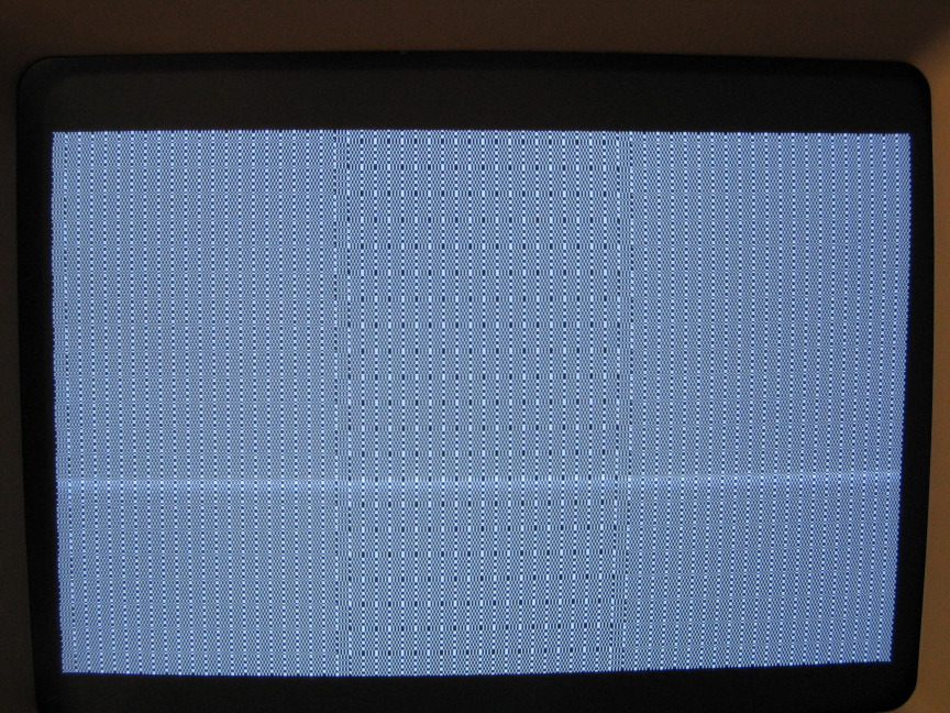
I get no horizontal lines at all. My vertical lines only appear with my fx rom. With the stock se/30 rom, i get no artifacts vertical or horizontal lines.
Regarding the Daystar 030 50 mhz, I have 2 of these: one is a universal cache with no fpu and the other is a power cache with fpu. The latter is residing in my IIsi and the plan is to use that in the SE/30 if I am ever able to get my hands on a micron with grayscale. To test to see if se/30 + fx rom + 030 50mhz is compatible with high density disks, I put my universal cache sans fpu into my setup shown at the very beginning of this tread (but without internal hard drive). At that point things got interesting. When i tried to boot I didn't get the standard "boing" sound, rather it was a really static version of the normal startup sound. Then the machine would not recognize the SCSI bus and i got the disk with the question mark. I inserted a 7.5.5 Network Access boot disk and then got happy mac and the machine continued to boot. As it was nearly through loading the OS from the disk it threw an error (i didn't copy the exact words) along the lines of disk not recognized, cancel, eject or initialize. Since I knew what would happen with doors 2&3, I opted for door #1. I clicked "cancel" and got the same box again. I did this 3 more times with the same result. On the 5th time clicking "cancel", the box went away and the boot up completed with the network access disk which by the way was a high density disk. After the system was booted, the disk was present on the desktop and I could browse its contents. I shut down and restarted and got the same result, scary static startup "boing", scsi bus not recognized, had to boot from network access disk, 5x on "cancel" and then boot. My larger concern was that i had toasted my motherboard with the scary startup sound and external scsi not recognized.. I shut everything down and returned several hours later and replaced the 50mhz 030 with the turbo 040. Booting got my normal "boing" and external scsi drive was recognized...WHew! Note: in all cases with cold boot with Daystar 030 i got the vertical artifacts.
Now the SE/30 is running booted to 7.6.1 and when I insert the high density network access disk and now it can be read. It seems to take a long time before it appears on the desktop but it does appear. For fun I inserted a 6.0.8 boot disk that is on a high density disk and after some time this disk can be read. When I insert a non-boot high density disk, I get asked whether I was to initialize or eject (but no cancel). All very interesting...
Von, since you seem to have virtually no trouble with the Daystar Turbo 040, I guess we can rule out the IIsi PDS adapter as being the cause. So this takes us back to the motherboard capacitors again. While I would expect both the 030 and 040 cards to freak out if logic board capacitors were to blame, the fact is that the quirky audio you describe when using the 030 card seems related to bad capacitors. But then, you say that SCSI disks are not being recognized either. Now that would not be related to the capacitors. Could this SCSI problem be related to a missing Daystar CP/Extention at startup on the SCSI boot drive? Also, what happens when you try the 030 card with the stock SE/30 ROM?
Very interesting to hear you get those vertical artifacts even with the 030 card. I really want to know the root cause of those! The "Repair Macintosh SE/30" website claims these vertical artifacts are "early signs of SimasiMac," but I disagree. I mean, I've replaced all my motherboard caps with tantalum capacitors and I still get these vertical artifacts! Replacing the caps fixes SimasiMac, hence, there must not be a direct correlation between the vertical artifacts and SimasiMac. From what I read in your posts, it would seem to be related to the ROM SIMM connector. (Not the "ROM SIMM" itself necessarily, because as I've said before, I get those vertical artifacts even with my stock SE/30 ROM and no PDS cards attached.)
see posts here regarding Stratos Twin Spark adapter and reverse engineering aspirations.
I read that. There was some talk about trying to reverse engineer it but there didn't seem to be any success or progress and the thread eventually died. I have a TwinSpark adapter ordered by the way. How long does it take to ship?
Aspirations are everywhere on this site and 68kMLA, but it's a rare event when someone truly produces something new. Manabu Sakai produced something new and decided to charge and arm and a leg for it. He knows most North Americans are all talk and no walk ("aspirations"), so he continues to charge nearly $200 for the TS Adapter and sleeps well at night doing so.
I'm not defending Manabu in saying this. Rather, it is my hope to inspire others to do more than just "aspire" to greatness. Greatness takes hard work.
As to the shipping, I would think you would get such answers from Manabu Sakai, as he is the seller. If you've paid, he'll ship right away (most likely by EMS), which means you should have the board in 3-4 days.
In the thread linked to in an earlier post, I did pretty much defend him. When you look at all the costs associated with such a project and trying to predict how many of the product to have on hand or might eventually sell at a price not below the cost of materials and time to assemble, his price is not so outrageous.
If you figure there's about $40 in materials in each of his boards and he has about three hours of prorated time invested in each board (1 hour reverse engineering, 1 hour board layout and design, 1 hour asssembly) his price starts to look more reasonable.
Then consider the conundrum of ordering printed circuit boards. If he orders as few as five, he'll be charged about $50 - $80 each for the boards. If he orders as many as 200 the price will drop to something more like $15 - $20 each. It is not a complex board but board fabricaters charge by the square inch.
But, if he orders 200 boards he must invest $3000 - $4000 up front and hope he sells enough units to make up the cost.
One way to help make up the cost (and relieve that anxiety of his) is to charge a largish price so that his costs are covered with the sale of not too many units.
How many of us can afford to have $4000 tied up in such a project? That's what it takes to get the costs down to the point where he's making a decent profit (or getting paid for his time).
The economics of these small quantity projects is not heartening.
My experience for these comments is based on making a run of Beige G3 ROM DIMMs and my current IIfx 16MB SIMMs.
Well, JDW is probably right. Still stings a bit though. I did (do) have aspirations to reverse engineer the PLD on the PDS adapter. Trag is the voice of pragmatism, but that still doesn't make me feel any better about the cost. I've been keeping an oar out of this thread, since I've got ideas and no results. I do have a working IIsi adapter now that I didn't at the time of catmistake's thread reference. So reverse engineering without stepping on Manabu's toes is a possibility. What I need is time. With the lack of any true skill, I have to make up for it in time invested. So, that being said, I still intend to reverse engineer the PLD, and if successful, get it into the public domain. Trag is right. In a niche market like this, how many of these are you really going to sell (maybe a couple of dozen)? If you can't sell many, then they have to cost $$$. I'd rather the design be out there like the ROM SIMM design on Gamba's page. If you can make it-props to you, if not, buy it from Manabu.
my $0.02
mike
Trag, I agree with most of what you say. But we both have to admit that costs come down over time, whether we like it or not. No one would argue today that just because Apple spent millions developing the Macintosh in 1984 that now, in 2007, a Macintosh 128k machine should cost the same $2,400 that it did (assuming one could find one new) back in 1984. Why? Because everything depreciates over time. The lone exception is Manabu Sakai.
Now, when I see someone talking about Manabu as being overpriced, I hesistate to chime in with them because most of these people would have complained about poor Manabu from day-one. I disagree with that stance. For indeed, when these items were newly released, they would have been worth every penny. But Manabu has been selling them for many years, with no updates, and not so great support in English either, and yet being sold at the same prices he released them at when he first released them to the world! And so, in light of this, we can see that Manabu Sakai, as of the date of this writing, is overpriced -- and this remains true even if one has a hard time finding similar items elsewhere.
It would be also good to note that Manabu is not responsible for designing every product on his site. I've pulled up some of his Japanese PDFs and found some logos on the products shown which contain a name. Googling for the name pulls up a company in China. That same company still displays the products Manabu sells, albeit under their own brand. So this proves Manabu has imported some off-the-shelf items from Chinese suppliers. This should further illustrate that he is not, in fact, spending all the R&D himself.
Why am I saying all this? To discuss "good business in general." Manabu would likely have been able to sell through all his stock (mostly "dead stock" now, I assume) had he been a good business manager and reduced his prices over time. You will never please all people that way, but you will show consumers that you are acting in accordance with other businesses. I do this myself in my own business. I also give discounts on a case by case basis. This causes many of our customers to go away happy and they bring us other customers via word of mouth. If only Manabu Sakai could do the same.
Nevertheless, Manabu has "the right" to do whatever he likes, even if none of us like it. (And part of my own "not liking it" is the reason behind my own personal quest for a 4GB SSD SCSI flash drive that is reasonably priced: http://www.dvnation.com/forum/mboard.php) But if you have the money to pay for Manabu's goods and if you really could use what he has, and if you don't need all that much support in perfect English, then Manabu will satisfy your need. I've bought several items from him myself in the past, so I say this out of experience.
We also must remember, Manabu's business will not last forever. There will come a time, for whatever reason, it ends. MicroMac anyone? Then, the very small number of people who had ordered the TwinSpark adapter will now own something even more rare than the IIsi adapter -- the ONLY adapter ever made SPECIFICALLY for the SE/30 which allows the use of an accelerator AND another PDS card with ZERO modification to the structure of the SE/30. If (when) that day comes, these TS adapters will be extremely rare and would most likely fetch quite a pretty penny on e-bay.
That's an interesting point and I mostly agree. However, the fact that prices come down over time is based on circumstances which may not apply in this case.
Why do prices come down over time? There are several reasons.
1) Technology/efficiency improves and it becomes cheaper to make the item. *** This one is unlikely to apply in the case of a homemade/handmade item. However, it might apply if the Twinspark is coming from a manufacturer in China.
2) Once the non-recurring costs of a product are covered it is reasonable to sell it for some amount above the marginal cost to produce each unit. *** In this instance this would apply if enough units have been sold to cover Manabu's initial investment of time and (most) of his money. I do not know how many units he has sold, nor how many he originally produced. If he produced 200 units, at his current prices I'd say he could lower his price comfortably after selling 30 to 40 units. Has he sold that many? More?
3) If one has a large profit margin, one will often lower the price to maintain a high or at least steady demand. *** This is only a good strategy as long as you don't start losing money on each sale, unless your goal is to liquidate and take a loss.
In my own case, I usually use Ebay and let the "market" set the price. In the case of the Beige G3 ROMs, I used regular auctions to find out what the regular price seemed to be and then sold at a fixed price until demand wained. Then I would use a couple more conventional auctions to find the new market price and then go back to fixed price at the new level.
I guess this more or less follows what you describe as good business practice. My thought was that I was selling an item for which demand would quickly be outdated so I better unload as quickly as I could consistent with getting a good price.
However, in the case of an accessory for the SE/30, is demand likely to change much over time? The machine is already so far beyond its expected life, I would expect the demand to be pretty stagnant. There will be some group of people with an interest and maybe a very few new people entering the interested group. So why hurry to sell all his units?
The only reason I could see is that the demand is likely to be tiered. There are folks who will pay his price. There are other people who are interested but who will never pay the price he currently has. If he would like to sell to the latter market, then he needs to lower his price.
Then there are folks like me who are interested but think it will be way more fun to invent my own solution. If I could just get out from under these IIfx SIMMs, I could move on to the next project...
Well then please invent a 3.5" NAND flash drive with a 50-pin SCSI interface in a 4GB size that costs around $200 or less!
Yeahhhhhh. That's not going to happen.
Once I finish assembly on the IIfx SIMM circuit boards that I have on hand, the time available for projects will go into redesigning the Daystar IIcx adapter to see if it can be made to fit inside the SE/30 with room for a PowerCache or Turbo040 on top.
After that, I'm either going to try to clone the external floppy drive for the Outbound 125, or I might get serious about a new video card for the SE/30 using FPGAs. But given that I seem to spend 1.5 - 3 years on each project between meandering research and education and then drawn out production, no one should hold their breath.
I have this fantasy... Of a new combo card for the SE/30 which would plug into the PDS slot and provide dual video output, IDE drive support with a connector for 2.5" drives, and (really dreaming) USB. The latter is really dreaming because I suspect that the effort to develop usable drivers would be a much larger programming project than I could complete on my own.
For USB getting HID events and translating them into Mac System calls shouldn't be hard. Getting it in the system to be functional at boot, as a new system ROM or a card ROM would be the biggest hurdle, and that should be possible, but at a possible expense of breaking compatibility somewhere.
I wanted to provide an update for those reading this thread many weeks or months from now...
I just noticed that all the posts about SCSI on the following forum were deleted as of today:
http://www.dvnation.com/forum/mboard.php
(I had posted this link earlier in this thread.)
I would therefore be extremely cautious of the seller in light of this, especially because he had written some very positive posts in that thread. It's clear now though that he cares little about the classic Mac community. Probably best to acquire your flash drives elsewhere on the net.
My hope though is that Apple's continued interest in NAND flash will cause more manufacturers to use NAND flash in the future, which will pave the way to flash drives in most computers, not just notebooks. That will not only drive prices down close to what they are now in the spinning disk world, but it may also open the door to a 3.5" SCSI NAND flash drive solution too. At least, I hope so! Our classic Macs would love us for using that! Low power, no noise, no heat!
That looks really clumsy, fragile and failure prone to me.
I've been trying to get my head around the geometry of dankephoto's suggestion too; EDIT/ after further thought and simulations with props, yes, it looks like the pinouts would be reversed.
Here's a suggestion that makes the chain shorter but keeps the correct pinout orientation:
Unsolder the PDS connectors from the video card and the top slot of the IIsi adapter. Swap them over, so that the IIsi has an upward facing right angle, and the video card has a normal connector.
If you can source a second right angle connector, mount that facing upwards on the video card.
Then you would only need two right angle adapters to make the connection.
Another suggestion: take the sockets out altogether and solder /a/ ribbon cable/s direct from one card to the other.
However I can understand you not wanting to do any soldering on these relatively rare cards.
I gather the original problem is that the video card won't fit horizontally without colliding with the CRT yoke?
That soldering job would be over my head and I would like to keep the components stock. Even if that solder job worked, it would be too tall for the case.
THe first thing I tried was to have the rasterops card go horizontally and it collides with the tube...if only the pds pass-through on the daystar card was a few farther back towards the back of the case, it would have worked.
I have made progress on this original topic and will report back after my ski trip is over.
A ribbon cable connecting the cards was my original idea however I could not find anyone to do the work...
I have made good progress on this:

More to come...I'll post some photos after I get some sleep.
Von, I see you have a Daystar Turbo 040 and a non-stock ROM in your SE/30. I have the same setup (and my Turbo 040 has the latest ROM revision as well). Unfortunately, I found that on my machine, when I put in the Turbo 040 AND a IIsi or IIfx ROM, my floppy drive goes nuts. It still reads/writes 400k and 800k disks just fine. But it won't read/write 1.4MB floppies. But if I yank the Daystar (or put back in the stock ROM), the floppy drive goes back to normal and HD floppies work fine again.
Could you test this on your setup?
Assuming you have the latest ROM revision on your Turbo 040, and assuming that your system can read/write to 1.4MB floppies, then I can only assume the incompatibility in my setup lies with the TS Adapter (from Manabu Sakai of ARTMIX Japan).
Thanks!
Oh, I meant also using the right angle adapters to reach the other card, just fewer of them.
Making, or getting made up, a short PDS ribbon cable is possibly your best bet. It would leave the cards stock, let you mount the last card anywhere convenient, and connect them with the smallest possible number of connectors. I would be willing to bet that a short enough cable would present fewer problems than all those right angle connectors.
I agree with you on the ribbon cable. I tried several iterations with the connectors with mixed results. My 2/27 diagram unfortunately did not work as the last u-turn to the video card would not fit. My 3/7 screen capture used this configuration in with the internal hard and floppy drives are removed (booted from my external hard drive):

The top card is a Daystar IIsi Dualport Adapter that I recently acquired on ebay (sorry dankephoto).
In order to get everything to fit I had to use another Daystar card mentioned here and shown below.

This card supplies 2 PDS ports of which I used only 1.
I had to use the second Daystar card as when I tried to get the Daystar Dualport on its back using connectors as shown here:

The system would not boot. When I removed the Turbo 040 it would boot and the Rasterops video card was functional. I don't think the 040 liked that many connectors...
In this screen capture:


It is the same working configuration as above except that there are 2 additional straight connectors beneath the Asante network card in order to give enough lift for the hard drive to be mounted to the floor of the chassis using existing holes.
THere are also 2 additional right angle connectors to get allow the video card to fit. This allowed the system to boot from the internal hard drive.
When I attempted to remove the hard drive and raise the network card with 3 straight connectors so that the floppy drive could fit, the system would not boot. Again, I think the issue was too much of a gap between the motherboard and the Turbo 040.
I put the system back together sans floppy drive but added a cover for the floppy drive slot and added a LED to the hard drive:


That looks like this from the outside:
My next step will be to try and build the PDS extension cable using 2 of the straight connectors. I will shoot for the shortest distance between the Daystar Dualport adapter and video card...something close to this:

I'll report back on how it turns out.
Those PDS connector pins are very thick. I don't see why it wouldn't work, even if you had three times that many connectors. Again, because those pins are so thick, there is not much added resistance in between the logic board PDS connector and the Daystar Turbo 040. I can only assume you had a bent pin somewhere?
Alo, there's signal degradation and timing skew over longer distances. The PDS wasn't meant for more than a few inches. Getting it to a foot or so introduces a lot of possibility for small errors to build into to trouble.
Again, if we are only talking a foot or two feet, there is not much resistance being built up in those thick metal pins. Perhaps if they were a 5th of their thickness, yes. But these pins are thick.
The only thing I can think of is inductance. This is a concern as there are high speed signals being sent and received through the PDS connector. And you are putting a lot of "turns" in the middle with those connectors. Inductance would cause signal degradation, as Jon mentions. And the only way to eliminate inductance of that sort "easily" would be to have a straight line of sight path, which in this case is impossible.
Von's setup has been an interesting test, however, as it shows that other SE/30 "PDS card solutions" such as the TS Adapter from Artmix could have problems too. Although the TS Adapter only uses one 90 degree angle, still that is not a straight path and boards you attached to the TS adapter are separated by several inches from the logic board PDS connector. It is therefore theoretically possible that some signal errors could be introduced into the circuit with the use of such an adapter, possibly causing a crash/bomb now and then. I have a TS Adapter myself and while it works well for the most part, there is a crash now and then I cannot explain. I suspect the root cause may be the same (inductance) as that which prevents Von's setup from working with the Turbo 040 installed.
The pins on my connectors are thinner than the male pins in all of my PDS cards. Remember these connectors were meant to be be soldered to a board, not snapped together. The straight connectors do snap together nicely. THe right angles to have much more play once the are inserted.
In the "The system would not boot. When..." photo above there are 9 connectors that make 5 90 degree bends. At 120 pins per connector, that is 1,080 possibilities for trouble.
The working system with internal hard drive has 2 straights below the Asante card, 3 right angles + 1 straight to connect the 2 Daystar cards, 1 right angle to get the 040 horizontal and then 2 more right angles to fit the video card in. That is 6 connectors and 4 right angles before the 040 works, then when I remove the HD and add 1 more straight under the Asanate to fit in the floppy, it fails.
I still need to go to Radio Shack and buy wire to start making my cable. I looked at trying to make the cable from a 50-wire scsi cable and an older 40-wire IDE cable and decided to go that route in case I make a mistake part of the way through the job. Can someone make a recommendation on the gauge of wire to get?
THx
I know that some people are using IDE cables for use with relocating the VRM on old G4 Cubes (read about all that on CubeOwner.com). But I for one feel that such is just too thin. With the power consumption of a Turbo 040, you can't go wrong with using 18 AWG wire, but that's awfully thick for multiple strands. I wouldn't advise thiner than 20 AWG though.
The original Mac 128k used 22 AWG to route wires to the logic board. Pina's book advises strongly to replace with 20 AWG or 18AWG for machines that have been upgraded in any way. This is partly the basis for my own recommendations to you.
Pages