
Anonymous
User login
Please support the defense of Ukraine.
Direct or via Unclutter App
Active forum topics
Recent content
Navigation
No Ads.
No Trackers.
No Social Media.
All Content Locally Hosted.
Built on Free Software.
We have complied with zero government requests for information.
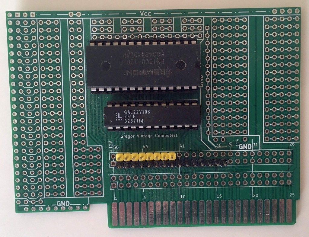
I would like to present a prototyping card for the Apple II computer,which I designed and have been using for some time.This card comes in handy when I want to quickly build or design a new device.It can also be used to construct other cards—for example,based on a schematic diagram.Furthermore, it allows for the execution of custom code during the computer's startup process.No additional tools are required to write programs;the built-in ROM monitor and/or BASIC are sufficient.The card is ideally suited for creating or testing software for any Apple II expansion.It is equipped with 8 KB of memory divided into four banks of 2 KB each.These banks can be switched via software; they are mapped to the $C800–$CFFF address range.A 256-byte segment of the fourth bank remains permanently visible in the $Cn00–$CnFF range.Bank switching is performed via software.After a system reset, writing to the card is disabled, and the memory in the $C800–$CFFF range is disconnected.It can easily be unlocked via software to enable writing.Once unlocked, the card behaves like standard RAM,allowing for free modification of its contents using, for instance, the built-in monitor, BASIC, or an assembler.Any access to address $CFFF causes the card to disconnect from the $C800–$CFFF range;however, it remains visible in the $Cn00–$CnFF area (where *n* represents the slot number).
The card retains its contents after power is turned off and does not require an additional power source to maintain the data.
It looks very nice, but my suggestion would be that the prototyping area maybe could be a little larger, as there isn't enough room to put sockets for larger chips someone might want to hook up like a 40 pin DIP or something like an ESP32 or RPi Pico module for example.
But the ability to program an EPROM or EEPROM and have it be addressable on a card like this is definitely super valuable.
Many PCB manufacturers offer good pricing if the design fits within 100x100 mm—hence this limitation.Of course, there is nothing stopping you from designing a larger PCB; I simply didn't need one—at least not for now.
If more surface area is required, I attach additional boards using a simple connector that allows for either a permanent or detachable connection between two PCBs.
I have included example PCBs for ICs in DIL packages and for the STM32H750 module.
DIL_1.jpg
STM32_1.jpg
STM32_BASE.jpg
That solution looks like it would be workable, but I'm not sure all those extra connectors to hook the two boards together don't pretty much negate any cost savings from the smaller base board.
So is this something you are planning to sell, offer a kit or publsh the designs so other people can fab them?
These connectors aren't essential for the connection; I actually needed them for a project I was working and used one of the extra PCBs.However, following your suggestion, I designed a new PCB.
Screenshot (729).jpg
That size ooks great! Lots of room to work with.