The first working(-ish) homemade MMU
Back in early march, I dug out my old Apple IIe computer from my parents's garage. That was a fantastic find and I wanted to play again all those games from my childhood. Unfortunately, the computer did not power on. While searching on the internet, I was sidetracked while reading on the MMU and IOU and their lack of replacements. And then I foolishly though that attempting to re-create the MMU and the IOU with a FPGA would be a good idea. Surely, it can't be that hard...
I was surprised at first that this hasn't been done already but, as I read and struggled with the old schematics, I understood. They're incomplete, sometimes inaccurate and absolutely obscure, hostile and ingrate to those who weren't involved in the IIe's development. A fool's errand, and anyone except the most obsessed by the IIe would see this as a waste of time.
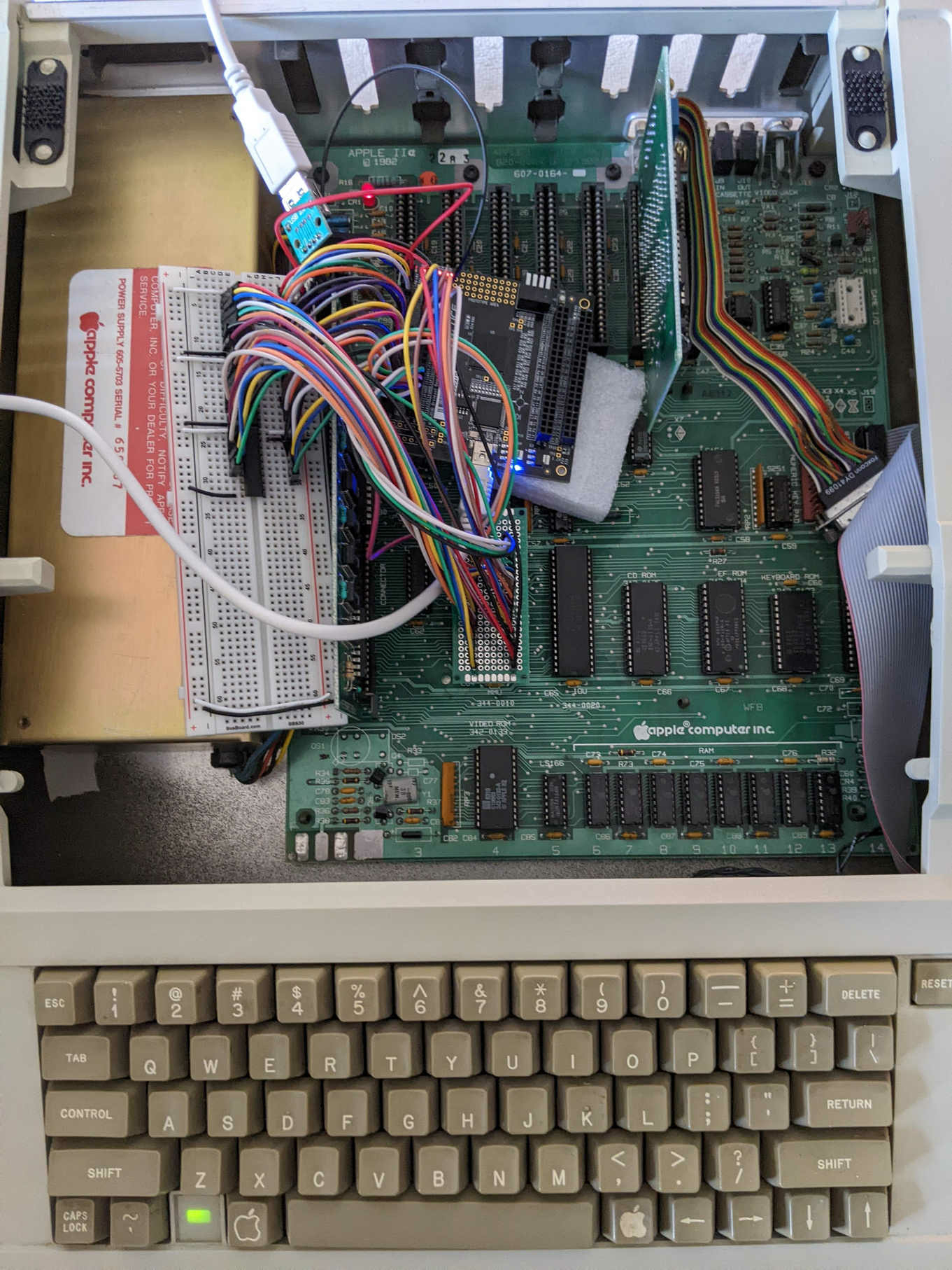
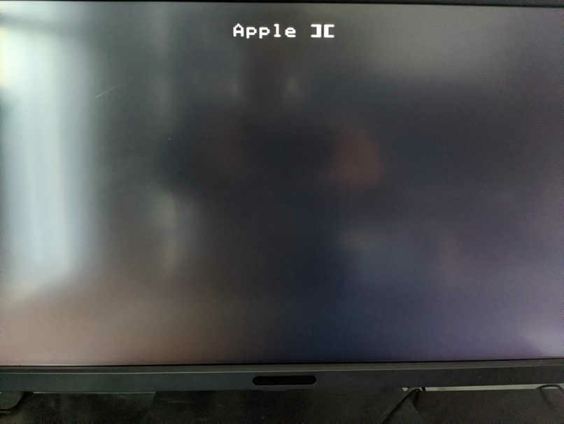
So after two months spending most of my free time on this, here is, to the best of my knowledge, the first homemade MMU:
The homemade MMU displays the booting screen with the beep. I can drop into Applesoft, but it can't load a disk; sometimes it loads a few sectors and hangs, other times it drops into the monitor. I think it's either a timing problem or the fact that the outputs of the homemade MMU are 3.3v and it's not high enough. I used a Lattice MachXO3D FPGA and the +5v inputs of the MMU are converted to 3.3v through 3x 74LVC245, and the 3.3v outputs of the FPGA is direclty fed to the Apple IIe motherboard.
My code is based mostly on the logic schematics, but often I had to confirm the behavior with the ASIC schematic and the books I could find. Sometimes I even had to hook the oscilloscope and confirm with an actual MMU. Anyways, I will upload my code on github, but before I'd like to make sure the problem I have is not a problem with the code.
- frozen signal's blog
- Log in or register to post comments


Comments
Sounds like a fun project!
Sounds like a fun project! You still have space on your breadboard: you could add a 5V powered 74LS245 to boost the MMU outputs before feeding them to the mainboard... ;-)
Sooner or later someone had to start work on a MMU/IOU replacement. In any case, that's going to be a good start!
Very exciting! Here's a link
Very exciting! Here's a link to frozen signal 's earlier MMU discussion, for those finding this post from the front page.
Question about your IOU VHDL
Hello FrozenSignal,
I've spent quite some time trying to make a software emuation of the IOU, especially fof the video signal generation. I have reproduced all graphics modes but still, I find something quite strange in your VHDL and I wonder where it comes from (different Apple model ? PAL vs NTSC ?). I have looked at the code here : https://github.com/frozen-signal/Apple_IIe_MMU_IOU/blob/master/IOU/VIDEO_GRAPHICS.vhdl
(I try to reproduce it here but I thing the forum doesn't handle the typesetting correctly)
begin
if (rising_edge(PHI_0)) then
-- IOU_1 @B-1:R5-12
PGR_TXT_N_INT <= (MIX and V2 and V4) nor ITEXT; -- Called GR in "Understanding the Apple IIe" by Jim Sather
-- IOU_1 @B-2:N6
-- The value of PGR_TXT_N_INT is GR+1 in "Understanding the Apple IIe" by Jim Sather
if (PGR_TXT_N_INT = '0') then
SEGA <= VA;
SEGB <= VB;
else
SEGA <= H0;
SEGB <= HIRESEN_N;
end if;
SEGC <= VC;
LGR_TXT_N <= PGR_TXT_N_INT; -- Called GR+2 in "Understanding the Apple IIe" by Jim Sather
end if;
end process;
In particular, I understand the following:
- The expression (MIX and V2 and V4) nor ITEXT means GR and is valid at any time (exactly what one can find in Sather's book)
- PGR_TXT_N_INT aka GR+1 exists only internally to your architecture and only during a rising PHASE0 (so almost an instant). So basically GR+1 is totally local to this part of the IOU.
- LGR_TXT_N is a copy of GR. It will hold its value for at least one PHASE0 cycle. That effectively makes it GR+1 (plus one, not two).
Do I understand your code correctly ? If yes, it means there's no such thing as a GR value delayed by 2 cycles.
Thanks!
Stéphane
Hi, this is a great project!
Hi, this is a great project! Has it been finalized with MMU and IOU being fully emulated? I am interested to participate as a tester if needed.