Hi guys,
I'm unsure how to setup the RAM banks on the apple 1 or what the letters mean. I already havea 64KB RAM and rom card installed as well. What do the numbers and letters mean here?
Hi guys,
Please support the defense of Ukraine.
Direct or via Unclutter App
No Ads.
No Trackers.
No Social Media.
All Content Locally Hosted.
Built on Free Software.
We have complied with zero government requests for information.
~ Est. 1999 ~
A pillar of corporate stability since the second millenium.
© 1999-2999 Tom Owad
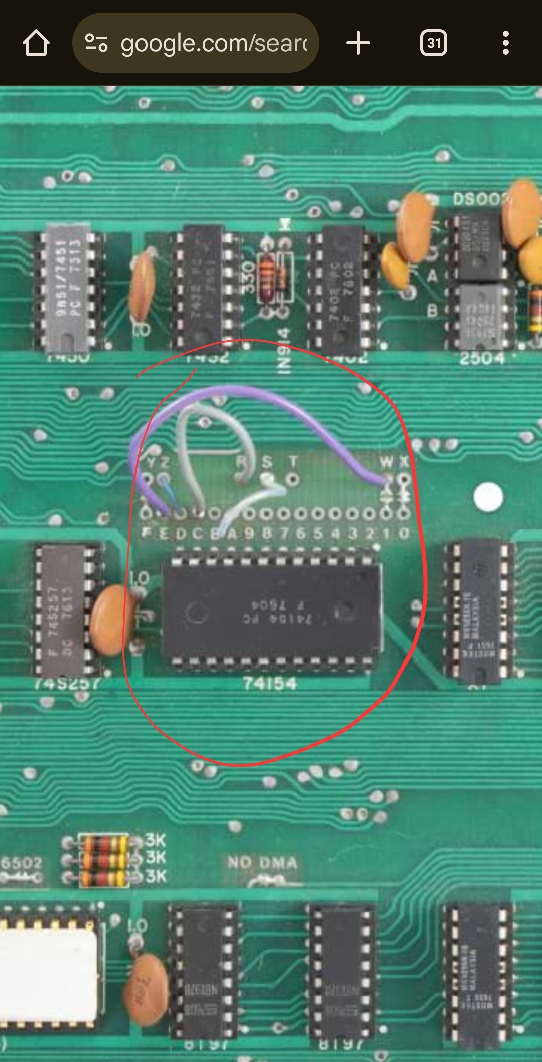
The Apple I schematic tells the tale. The points "FEDCBA9876543210" are each 4KB chunks of the 6502's 64KB address space:
"F" is all the addresses that begin with the nibble F; in other words, $F000 through $FFFF,
while "0" is all the addresses that begin with the nibble 0; in other words, $0000 through $0FFF.
The other letters represent functions such as RAM, ROM, and I/O.
W and X are the two banks of RAM on the board. Y is the PROM on the board. Z is the 6820 PIA I/O chip on the board.
R, S, and T are signals that can be used by peripherals in the expansion slot.
Jumper wires map each of these functions into the chunks of memory the user desires. Normally the PROM must be mapped to chunk F (because it is the location of the reset vector at $FFFC which will be read when power comes on) and the RAM must be mapped at chunk 0 (since it contains the zero page and stack used by nearly all 6502 code, from $0000 - $01FF). The on-board I/O must be mapped at chunk D. The rest is up to the user based on which software is to be used.
Wire Y should be connected to F to enable the PROMs.
Wire Z should be connected to D to map the PIA to the default location used by the PROMs.
Usually wire W goes to 1 if you want the second 4K mapped to 1xxx and wire X goes to 0 if you have RAM installed in both rows and your Apple I should work without the RAM card it is recommanded to be set like this.In your picture W is wired to E that is the case when you want to load the Basic from Tape there, with your card you better connect W to 1 and set E on the RAM/ROM Card to ROM.
I would recommend to remove the violet wire and close the jumer between W and 1. That will move the 2nd 4K from Exxx to 1xxx as the RAM/ROM card below expects it.
If you want to use an ACI you need to wire R (I am confused the A1 schematic says T is on pin 21 and the ACI manual says R needs to be connected I guess the schematics is wrong) to C to map the ACI IO and PROM to the default location Cxxx. Without the ACI will be ignored.
It is unclear why in your case S is connected to A but likely an additional card was used.
Your RAM/ROM card should have the right instructions to set everything up.
Is that your card: https://www.tindie.com/products/jurassicomp/apple-1-64kb-romram-card/?
This card seems to support up to 32K RAM and and up to 32K ROM.
Let's say this card is a bit special.
And the documentation could be a lot better.
Found some information in the GitHub that might give a clue and even more confusion.You can map a ROM Block into zero, one or into two regions.
The Jumpers depend on the EPROM content.
This memory map does not fit to the jumper setting pictured above! can you post a picture how it looks for you?
On the card Jumper 0,1,D and F should be open as this regions are used by the Apple-I mainboard.
If you use the ACI C should also be open.
From the 32KA1COMPIL.json you can see the following Jumpers should be set to ROM: 2,3,4,5,7,8,9 and E
That leaves A, B, and if no ACI is used also C to be jumpered as RAM.
If you do not want to rewire W from E to 1 Jumper E needs to be open on the card as well, in this case you can set Jumper 1 to RAM if Jumper 1 is set to RAM you should not set Jumper 9 to RAM as well.
As your 2nd 4K of RAM are configured to Exxx you need to remove jumper E on the card.
Note the default config as of the RAM/ROM card pictures assumes that you have configured W to 1 and do not use an ACI.It adds 32K of ROM with one mirror 6xxx and Exxx is identically I have no clue why they are doing that.
The EPROM has a autostart function that would require to set Jumper F to ROM and remove the solder block from the Jumper between Y and F to deactivete the PROMs.
in this case the same ROM would be at 7xxx that whole card looks like a big mess the person who did it seems to have got 10 more ideas while creating it.
I can not recomand to buy this card unless you are able to build (not only program) your own EPROM or at least till there is a useable documentation.
There is also an alternative EPROM wozdle, but files are missing you can't build it.
I think this card is over priced and not very well designed and the documentation is a bad joke.
Using two 32 pin sockets would have given it a lot more flexibility and less quirks.
And before you use it bevel the edge connector with a file to not ruin the connector.
IMG_20250725_173735.jpg
IMG_20250725_180226.jpg
You absolutlely need to set the bridge between Z and D otherwise the computer part is unable to receive key presses and display output on the Terminal part.
Do you use that RAM/ROM card ord a different one?
If it is the one I pictured you need to set the following jumpers 0,1 to RAM.I guess you also need to set F to ROM to replace the onboard with the EPROM.Let me check if the EPROM has the right content for that.
I just did set D to Z but it does the same thing as before. It just glitches for a second and then it goes back to the @ symbols again! Also I have no RAM installed in the apple 1 because I set my 64kb ram and rom card to replace all the roms and ram
Also I am using a TV because its the only thing that will display an NTSC signal because I am in a PAL country and none of my other TVs detect the signal.
It is for sure for the RAM, for the ROM I just checked,
The Jumper F needs to be set ROM and at least 2 as well.
Because this ROM autostarts configured like this.Can you share the jumpers on your RAM ROM card?
May I ask if it's a German speaking country?
IMG_20250725_185044.jpg
Even without a populated computer part you should get a different pattern and the @ blinking.
_@_@_@_@_@_@_@_@_@_@_@_@_@_@
_@_@_@_@_@_@_@_@_@_@_@_@_@_@
_@_@_@_@_@_@_@_@_@_@_@_@_@_@
_@_@_@_@_@_@_@_@_@_@_@_@_@_@
_@_@_@_@_@_@_@_@_@_@_@_@_@_@
_@_@_@_@_@_@_@_@_@_@_@_@_@_@
_@_@_@_@_@_@_@_@_@_@_@_@_@_@
_@_@_@_@_@_@_@_@_@_@_@_@_@_@
_@_@_@_@_@_@_@_@_@_@_@_@_@_@
_@_@_@_@_@_@_@_@_@_@_@_@_@_@...
Please follow this guide word by word: http://www.myapplecomputer.net/docs/MimeoBuildGuide.pdf starting on Page 15
Please only populate the Chips mentiond on page 16
And check if you get the picture on page 17
If you would have been German speaking I would have recomanded a German Speaking Forum.
So far we know most if not everything of the clock circuit is working other wise you would not get a picture.
The 2513 Char ROM is working as we can you see @.
Also the 2519B Shift register is fine as we see 40 characters in a row.
So far we don't know if any of the 2504 Shiftregister are working.
When clearing screen aka shorting pin12 clear screen against pin 16 +5v of the same socket the screen should get blank what would prove the 2504 are working.
When the card is jumpered like this the computer will crash on the first instruction.
You need to Jumper at least 2 to ROM to activate the MENU.
I even would set 2,3,4,5,7,8,9 and E to ROM
What tools do you have? DVM, Oscilloscope, Logicanalyzer, EPROM-Programmer (what type) Retro Chiptester?
FB_IMG_1753466838104.jpg
The Char ROM actually seems to work (@), but from the looks of the screen I suspect at least a problem with the 2519.
If you can buy the parts for this project you easily can afford an oscilloscope. Here the proof:https://aliexpress.com/item/1005006019697163.html
https://aliexpress.com/item/1005008143605070.html
Not that I would recommand any of them but both should be enough for this task.
@peo2000 I asume the 2519 working fine otherwise we would not see 40 characters in a row.
Removing IC-C4 would give the posibility to set bit patterns on pin 4, 7, 9 and 12, easiest with two resistor between 1k and 10K between one of the listed pins and pin 8 (GND) and another between another listed pin and pin 16 (5V). Pin8 (GND) -[10K]- Pin4 (Za) and Pin16 (5V) -[10K]- Pin12 (Zd).
That should change the @ to H or N depending how the 2513 reacts on open inputs.
A none working 2504 on position IC-C11B would have the effect that nothing blinks and only @ are shown.
The cursor is not blinking, we already know that, so first thing to check would be pin 3 of IC-D13 an analog voltmeter should clearly go up and down even a DVM should switch between zero and around 5V.
The terminal section is definitely not working.
And before that, it doesn't make sense to discuss any memory/RAM/ROM mappings or substitutions.
I would first rip out the entire CPU section (except B2), and on the top half everything on 2513/2519/2504, checking them step by step.
Without 2513/2519/7x2504, there should be an "endless carpet" of non-blinking "█".
With the 2513, the "carpet" should be non-blinking "@", as shown in the above post.
Then with 2519, there should actually be a 40x24 "frame" of blinking "@"s, which you can temporarily blank with Clear Screen.
After that, they should continue blinking.
If you now plug in a 2504 on C11B, you would be able to permanently delete the blinking content with Clear Screen, and only a single @ would blink.
...I would try to achieve this first...
That basically following the setup guide as proposed before. http://www.myapplecomputer.net/docs/MimeoBuildGuide.pdf page 15+
Does your Multimeter have a Frequency Counter?
If not think about getting at least something like that:
https://www.aliexpress.com/item/1005007383299753.html
And to test more static levels a logic probe is very help full:
https://www.aliexpress.com/item/1005007695539190.html
Why do i need a frequency counter? Is it for the 14.31818MHz crystal or for a clock signal?
I also get a voltage swing on pin 3 of the 555 timer from about 2.4V to 3.9V. Idk if its good or not
IMG_20250725_205207.jpg
I really start to get pissed, how about answering instead of asking questions?
No one is interested in that undiveded 14.31818 MHz but if the fractions are correctly appearing on serveral pins, and as you don't have porper tools for such a project we need to get creative as you prefer to pay money for stuipd nonsence like an Apple 1 instead for proper equipment.
Back to topic for example it would be a good idea to check the characterclock on Pin 6 IC-C3 that should be about 1,95 kHz. Because we have NTSC 15,6 kHz line frequency and a character is 8 pixels wide.
The cursor pin3 IC-D13 should blink with 2Hz.
For this the logic pen would be fast enough but for the characterclock that is named line 0 because it is only on every 8 lines for that reason the reading can be anything between 243 Hz and 1,95 kHz.
To really see that you would need an oscilloscope or a logic analyzer a cheap one is https://www.aliexpress.com/item/1005007096801617.html is around 5€.
The logicanalyzer software can also measure Frequencies and display them.
It should be 0V half a second, 5V half a second alternating.
What kind of DVM is that? Seems to be too slow to be usefull.
Try a low current LED and a resistor calculated for 5V it should blink like the cursor.
Why is there a resistor over the big upper capacitor?
Don't worry too much about your cursor timer for now; an average value of around 2.5-3.9V measured with a DMM is quite plausible, depending on the meter.
You should first get your video output under control.(See my previous post)
BTW, you have the really hard-to-get components on the board. I don't understand why you don't also install RAM and PROMs. If you need PROMs, someone here will surely help you. I can even burn some for you...
My 64KB RAM AND ROM card HAS ROM already programmed with firmware. I have configured it to work by replacing all ram and roms using the jumpers on the expansion card
My 64KB RAM AND ROM card HAS ROM already programmed with firmware. I have configured it to work by replacing all ram and roms using the jumpers on the expansion card
I expect at least one if not all AM2804 broken or fake.
If all seem to be broken there is a chance that the DS0025 is not delivering a propper clock that could be checked either with a frequency counter or even better with a logic analyzer.
Also the 2519 is not proven to be good.
No one cares for your ram rom thingy we even asked you to remove it and the CPU and all other ICs in the lower half beside B2.
And you configured it wrongly, as already mentioned CPU will crash on first instruction.So far I identified that Jumper F 2 and 7 need to be set to ROM.E on ROM if you want Integer Basic at Exxx.
We will take care of your RAM ROM thingy when you sucessfully fixed the terminal section.
Peo2000 gave you in post #17 valuable information how to debug when the picture does not show up as shown on page 17 in the Bring Up Guide.
Im really sorry to say this, I dont understand what you want from me. Which ICs do you want me to take out?
Perhaps you should first familiarize yourself with the architecture of the Apple-1 and understand the most basic structures. You can actually find quite a bit of information on this, not only in this excellent forum, but also in numerous videos that explain it very quickly and easily.
In a very, very quick way: The Apple-1 basically consists of two unusually independent sections. The upper half of the board is essentially a simple video terminal, which is connected to the lower half, the processor section, via a serial connection. This also makes it possible to first put the often more challenging part, the terminal section, into operation independently of the function of the processor section.
The suggestion was therefore to first remove all chips of the processor section in the lower two rows A and B, except for the 7410 in position B2, in order to initially concentrate only on the functions of the terminal section.In the top two rows C and D, all chips should remain populated except for those responsible for storing the characters on the screen, which can then be fed in step by step to see what changes, as described in my post #17.
Okay i get it now. May I also ask what is the NO DMA jumper for?
The NO DMA jumper prevents that the DMA Signal is floating, it needs to be opened when a DMA capable card is installed. see Note 13 on schematics.There are no DMA-cards for the Apple-1.So far I identified that Jumper 2, 3, 4, 5, 7, 8, 9, E and F need to be set to ROM.
0, 1, 6, A, B can be set to RAM.
D needs to be open.
If ACI is installed don't set Jumper C.
Here is a map what is in the 32KA1COMPIL.BIN0000-0FFF (8000-8FFF) 1st 4K RAM if no onboard RAM needs to be set to RAM, RAM at 8xxx is inpossible same time1000-1FFF (9000-9FFF) 2nd 4K RAM if no onboard RAM needs to be set to RAM, RAM at 9xxx is inpossible same time2000-2FFF (A000-AFFF) MENU + Files, needs to be mapped as ROM, ROM at Axxx is inpossible same time3000-3FFF (B000-BFFF) Files, needs to be mapped as ROM, ROM at Bxxx is inpossible same time4000-4FFF (C000-CFFF) Files, needs to be mapped as ROM, ROM at Bxxx is inpossible same time5000-5FFF (D000-DFFF) Files, needs to be mapped as ROM, ROM at Bxxx is inpossible same time6000-6FFF (E000-EFFF) 4K RAM, ROM inposible or unused7000-7FFF (F000-FFFF) Apple ][ monitor, Mini-assembler, WOZMON FF00 patched with RESET VECTOR SET to 2000 (same ROM as Fxxx but other part used)8000-8FFF (0000-0FFF) Files9000-9FFF (1000-1FFF) FilesA000-AFFF (2000-2FFF) 4K RAM, ROM inposible or unusedB000-BFFF (3000-3FFF) 4K RAM, ROM inposible or unusedC000-CFFF (4000-4FFF) 4K RAM, can only be used if no ACI card is installed, if installed configure to unused!D000-DFFF (5000-5FFF) IO needs to be configured to unused!E000-EFFF (6000-6FFF) BASIC ROMF000-FFFF (7000-7FFF) Apple ][ monitor, Mini-assembler, WOZMON FF00 patched with RESET VECTOR SET to 2000 (same ROM as 7xxx but other part used)That 'resistor' is used to discharge the 5600uf 25v capacitor because it can hold the charge for quite a while.
Here is what I have done:
I replaced the 47pF ceramic capacitor at location B3 for the 74123N with a silver mica type as that's what I saw in one of the photos of the apple 1.
Then I got a better signal on the screen but still I cannot reset the @ symbols when i press the clearscreenbuttonon the PS/2 keyboard adapter. I have configured the 64Kb ram and rom adapter to replace both the ram and rom. I dont know if it's configured incorrectly or if there's something wrong in the system. I wish someone else could have a look at this as I'm really not experienced with memory and stuff
Why? Are you telling us that?
If you want help, do what you got told and don't try everything else.
Rip out your RAM ROM card put it aside.
Rip out all chips in the lower half beside B2.
And follow instructions.
If you don't do, than I am not gona help.
I have tried taking out the CPU section and testing without it but nothing seemed to make a difference to the screen
I wish someone else could help me. I'm kinda struggling.
You need to read over all of these posts again. Post #12 refers you to the mimeo build guide with specific instructions to diagnose the startup screen of the Apple 1. Removing all the shift registers and installing them back in as per the instructions will provide information to anyone willing to help you further.
Justin
Everyone is struggeling to help without information. Taking the CPU part out will not make it work.
To find what is not working you need to minimize the variables that can cause issues.
Unfortunate it looks like that you don't have any equipment that is required for such a project.
You only seem to have the skill to measure voltages and resistances but it's not even proven that you know how to propper setup and use a DVM.
We have no idea what kind of DVM you have, can it measure frequencies?
We don't know if you at least have a Logicprobe that can show Hi/Lo/Impules?
We know that you don't have an Oscillospe and think they are expensive equipment, so we can assume you have no clue how to operate them and what unexpensive models would be very helpfull to diagnose here.
We assume you don't have a Logic Analyzer either, some single parts you bought for your Apple I are far more expansive then the simple model that would help here very much.
We have no idea where you got your parts, so far we just know you did buy them of your own, so chances that some/all 2504 are broken or fake are very high. Same for the 2519.
Unfortunate the Retro Chip Testers do not support these chips and even if they would you likely don't have one.
And to me you give the picture of a Jobs Apple Fan Boy and not a Old School Woz Apple Fan (who would say Apple died after the Apple IIgs, when Apple started to go fully commercial and started to be the company for people that don't like to think for them self).
For me no one who is not interested in how Woz got that thing to work deserves having a working Apple I.
I would suspect the AM2804's as well, what is their source? You could try swapping some of those and observe for different screen behavior, it could be that a couple (or all) are broken. Double check your clear screen/reset wiring (see attached). I agree it is hard for people to help you here if you do not 'follow' their instructions and report back on this. Only then a proper diagnosis could be made. Let's keep calm and be nice to earch other.
https://github.com/renatasdgt/1024bit-shift-register-ic-tester/tree/main
This tester can at least identify broken or fake shift registers as use in the Apple 1.
I'm relative sure it can not do a certification test that would approve the chip is 100% in spec but that usually not needed.
2519 could be tested with some little code changes and a different/modified test PCB.
Picture borrowed from Forum64: https://www.forum64.de/index.php?thread/156948-apple-i-nachbau-testger%C3%A4t-f%C3%BCr-die-2504-1404-2804-schieberegister
IMG_5952.JPG
Here you find a good schematic for the Apple 1:
http://retro.hansotten.nl/uploads/apple1/a1%20circuit.pdf
From the info you gave us we can assume the green marked parts work.
The red marked parts are the parts that are likely related to you problem, the parts include all expensive chips relevant for the terminal section beside the 2513.
If the red parts are proven to be fine the yellow parts need to be investigated.
Without proper measurements, parts tests the only recommandation we can give you is get known good parts for the parts in red and maybe in yellow and try with them.
That is surely more expensive then buying measurement equipment or part tester.
If you wounder about the blue part that is relevant when the blinking and clear screen part is working.
IC C9:A in the blue area should be marked yellow as well.
We don't even know if the board is soldered propperly, are there forgotten solderjoints?, short circuits?, cold joints?
We don't even know for sure if the green marked parts are working 100%.
We don't know if you used HC or LS parts somewhere, and if you have any fake chips in your collection.
Screenshot 2025-08-09 075734.png
What I would do? get the 2504/2804 tester I introduced in my last posting.
Let the people know what knowledge and test equipment is availible, if I want that someone helps me.
Answer the questions that got asked.
ok... ive lost patience. ive bought a rom adapter and now i will use an AT28C64 with a single bank eeprom adapter because i dont think my 64kb ram and rom card works. also i have no ram so i bought some mk4027j-4. Hope that will do something.
Also, i used all 74xx series ICs when possible. i did not use hc or ls series or s series or something. there are also no bad solder joints
also, im really bad with using oscilloscopes. i have no clue how touse them properly
Beside the two 74S257N I guess, what is okay.
I really recomend you to build the 2804 tester and check your 2804.
As long as the Terminal is not working don't even think about the rest and your RAM/ROM Card.
Do you have anything to find out if on IC D11 Pin 12 (CL) you have a 1,023 MHz clock signal? Through Refresh waits the effective Frequency is 960 kHz.
That is needed for the Computerpart.
If you use your RAM ROM Card your complete Computer Part (lower two rows) should work with 5V only, not saying you should cut the other voltages.
This Apple 1 Clonehttps://github.com/DutchMaker/Apple-1-Mini uses the the same Arduino nano as the 2804 Tester.
If you connect the Arduino nano (programmed with https://github.com/DutchMaker/Apple-1-Mini/blob/master/code/firmware/SerialIO/SerialIO.ino) as follows and the ~1MHz clock is working you should be able to use a PC or Mac as keyboard and screen.
Even if the Terminal part of your Applle I is not working you should be able to test you Computer part and your RAM/ROM card like this.
MC6821-Nano IO-Adapter.jpg
If you lift pin 37 of the 6502 out of the socket and connect the output of a 1MHz oscillator to it, you should be able to run the Apple 1 with row C and D completely unpopulated as long as you use a RAM/ROM replacment as your RAM/ROM card.
It's maybe a good idea to have a look to this:http://retro.hansotten.nl/6502-sbc/apple-1/a-one/ you could use the 6821 the 6502 the EPROM and SRAM form your card to populate this PCB.
It would require to program a ATMega32 and an ATiny2313 it that would be an option for you.
I replaced one of the 74s257 because i accidentally installed it into the keyboard socket lol. Also my oscilloscope cannot measure frequencies in the MHz range as it only has a 200KHz bandwidth and i cant afford the high end models.
Build a prescaler really easy get a 74HCT4040
Connect 5V to Pin 16
Connect GND to Pin 8
Connect TTL Signal to measure to Pin 10
Pin 9 Signal divided by 2
Pin 7 Signal divided by 4
Pin 6 Signal divided by 8
Pin 5 Signal divided by 16
Pin 3 Signal divided by 32
Pin 2 Signal divided by 64
Pin 4 Signal divided by 128
Pin 13 Signal divided by 256
Pin 12 Signal divided by 512
Pin 14 Signal divided by 1024
Pin 15 Signal divided by 2048
Pin 1 Signal divided by 4096
If you want to measure 1MHz select select divide be 8 your Oszilloskop should now show 128 kHz.
Right here is a youtube video about my problem so you can get a better understanding: https://www.youtube.com/shorts/XbmJSzqk_rk
That video does not provide any extra info.
The answer is still the same:
Get some tools and start working.
How to ACTUALLY Use an Oscilloscope (Beginner-Friendly Guide!)
The alternative buy a set of 2804 and DS0025 that are garanteed to work.
To be on the save side get also a 2519 or a 2519 replacement.
Pages