
Over the past years, on every April Fool's Day, it has been my pleasure to show you one of my foolish Apple-1 projects.
The projects are "foolish" not because they don't work (they do work fine !) but in the sense that they were designed for a vintage computer microcosm which is so small (in terms of number of people involved in it) that such projects are expected to not find much interest, meaning: adopters who want to build one example for themselves. So why design and develop a project almost nobody else is interested in ?
Here is a quote from the late Steve Jobs:
"Stay hungry, stay foolish"
- Steve Jobs
Of course he did not mean that we should starve ourselves, or behave like fools - this would be illogical. What he likely meant was to never be statisfied, be always hungry for new ideas and improvements, and allow yourself to pursue "foolish" projects - because these won't have much competition. Most people are conservative - especially when it comes to investing time and money into projects - and so they prefer to follow well trodden paths. Which only can lead to boring "mee too" projects, not to disruptive breakthroughs. Under Steve Jobs, Apple created lots of disruptive (aka "foolish") products which turned out out to be stellar successes and made Apple Corporation one of the most valuable companies in the world. Just as one example for "foolish" in this sense: a google search tells us: "the colorful, translucent iMac G3 (released in 1998) is widely credited with saving Apple from near-bankruptcy". And when it was in the concept phase, there were plenty of naysayers who claimed: "nobody would buy that, it doesn't look how a personal computer should look !".
WHY THIS PROJECT ?
Yet another color graphics card for the Apple-1 ? Why ? Did the first one (called "GEN1" in the following) not work ? Or were there other problems ?
Before I will go into these technical details, allow me first to tell you why I think having a color graphics card for the Apple-1 may be important, at least for a few hard core aficionados. In his autobiography "iWoz", on page 187, he tells us:
" The Apple II, ..., was a phenomenal improvement over what I'd done before. I knew I wanted to have a computer that did color, for instance. I had built the Apple-1 from the beginning with chips working at the frequencies you would need to generate color on an American television, and I had planned to add color. But though I'd designed the Apple-1 so I could add color to it, I decided it would be better to design a fresh computer instead. "
So here you have it from the horses' mouth: the Apple-1 was not meant to stay B&W forever. Woz had planned its clocking scheme and the video signal divider chains such that it could produce color at a later time, after some minor hardware upgrades.
But we all know it never came to that. The Apple-1 had too many quirks and was soon phased out. Then came the infamous "buyback decision" to purge the Apple-1 from the field and to destroy them - which wasn't a "buyback" at all: as the story is told, instead of getting their money back, the deal was that for each Apple-1 sent back (to be destroyed, mind you !) the owner got a voucher for a brand-new Apple II at a discounted price.
And the surviving Apple-1 were essentially orphaned by Apple.
With the hindsight of 50 years, this rises the most powerful (and most feared) question in the Universe:
" WHAT IF ... ? "
So, what if Apple had not orphaned the Apple-1 and had continued to provide upgrades for it, such as new slot cards, one of which could have been a color graphics upgrade ? After fixing the reliability issues, of course, which had doomed the Apple-1 for a long time. But I've shown that by adding just six resistors, the Apple-1 DRAM works much, much more reliable. And I've also shown that a slight mod to the ACI input stage, its readback reliability from cassette tape could also be greatly improved. But none of this happened back then and instead of fixing the Apple-1, they decided to kill it off. Which from a business standpoint made sense, but still leaves a sour aftertaste. The brand new Apple II was the much better and much more capable machine, as Woz had learned his lessons from the Apple-1. The rest is history, as they say.
If you study the Apple-1 video circuits you will find that they are almost the same as in the Apple II, even using the same IC types (horizontal and vertical counters 74161, video shift register 74166, character generator Signetics 2513).
It would be possible to tap into these signals, use them to address a small (8 kBytes) graphics bitmap RAM, add a color burst signal, and get full color bitmap graphics. But doing this on an Apple-1 would need lots of ugly flight wires.
50 YEARS FAST FORWARD
Now, with the hindsight of 50 years, we can ask the "WHAT IF ..." again and add a color graphics capability to the Apple-1, just as Woz had intended to do half a Century ago. Of course, this color graphics system must use Woz' technology to be faithful. Which means such a color graphics card must be Apple II compatible. Just taking some old color graphics LSI chip from Commodore or TI would not meet these criteria. Others have done that and the reception was poor.
THE GEN1 COLOR GRAPHICS CARD
April 1st, 2023, I showed my GEN1 color graphics card, see this link:
https://www.applefritter.com/content/glimpse-uncle-bernies-apple-1-color-graphics-card
... which worked fine (at least for me) but it did have some drawbacks: when I started that project, I had adopted the self imposed doctrine that the color graphics card should plug into the Apple-1 expansion connector (not the sole slot, which is needed for the ACI) and must not require any trace cuts or flight wires added to the Apple-1 motherboard.
Alas, in the development phase of the wire wrapped prototype it turned out that some of the quirks in the Apple-1 foiled that plan. Some flight wires (but no trace cuts) were still needed.
So I had to drop the doctrine but now had a solution without using Woz' 'long cycle' trick for which he got U.S.-Pat. 4,136,359 "Microcomputer for use with video display". Adding a 'long cycle' would have required trace cuts and many flight wires to the unused NANDs in the 7400 at location C15 of the Apple-1 motherboard. As a side note, this patent for the Apple II was filed 11th April 1977 - just one year after the "Apple Computer Company" was founded and about 5 months after Woz began to wire wrap the Apple II prototype (AFAIK this started in November 1976). So the Apple II design and development phase happened at lightning speed - and this was only possible because of the lessons Woz had learned with the Apple-1.
For the Gen1 graphics card, I did use an alternate solution needing no 'long cycle' despite I knew - from my professional background having designed ICs for TVs - that this made the video signal unfit for modern, LCD based flat screen TVs - but I also knew it would work perfectly fine with CRT based, analog color decoder based TVs or monitors. Little did I know that it got so difficult (and costly) for other people to procure these old TVs/monitors in the 2020s.
The worst issue was that due to yet another lovely Apple-1 quirk: the 'write-through' concept I wanted to have for TEXT and LORES graphics pages turned out to be infeasable to do - these reside in the lower 4k DRAM bank of the Apple-1 motherboard, and one nasty Apple-1 quirk is that the address bus on the slot and the expansion bus gets scrambled whenever on-board DRAM is accessed, rendering the address useless for any expansion card. So the Apple-1 DRAM had to be disabled whenever the graphics card is plugged in.
All these technical compromises were ugly, and I was not satisfied.
GEN2 COLOR GRAPHICS CARD IMPROVEMENTS
In past 3 years I figured out a trick how the 'long cycle' could be implemented with no trace cuts on the Apple-1 motherboard and with only one short flight wire added. This allows generation of a better NTSC standard conforming video signal which also works with many LCD based TVs and monitors.
The 'write-through' was enabled by using an address latch and a VMA signal coming from the graphic cards which delays the scrambling action just long enough to capture the unscrambled address. I'm not 100% sure yet if the timing for this trick is not too tight to be viable for all Apple-1 (the tolerance of the 74123 oneshot time period plays a big role) but there also is a Plan B needing only one diode more on the graphics card and no further mods to the Apple-1 motherboard if the write through would not work.
Better period correctness of components used
I also found a way in optimizing and repartitioning the logic such that it could be implemented with MMI PAL16R6 which appeared in Y1978. The GEN1 card needed the programmable macrocells of the GAL16V8 which appeared in the mid 1980s. And I'm in the process to redesign the video ROM and associated logic to work with 2716 EPROMs. Which I think are more appropriate for a graphics card which might have appeared in Y1978, if Apple had decided to do that (2732 EPROMs were available in Y1978 but still very expensive compared to the older 2716 types, this is why even the Taiwanese Apple II cloners used 2716 EPROMs until the early 1980s).
Last but not least, I succeeded to throw out all the blanking signals and their associated logic. This fixes the quirk of the Apple IIe that it can't make a proper orange colored vertical line at the rightmost edge of the visible screen.
CURRENT STATE OF THE WORK
The prototype works but is not yet complete. The adoption of the 2716 without losing the lower case character set requires a re-write of my software which generates the video ROM contents. So at the moment I can only show HIRES graphics because this is the only graphics mode in the Apple II which does not require a video ROM to translate the video byte into appropriate dot patterns.
I also don't have any 74LS258 TTL in my stockpile and must order it, which has to wait until I have accumulated an order large enough to make economical sense. I have hundreds of 74LS257 in my basement, but I need its inverting cousin (the 74LS258) to avoid adding yet another IC package.
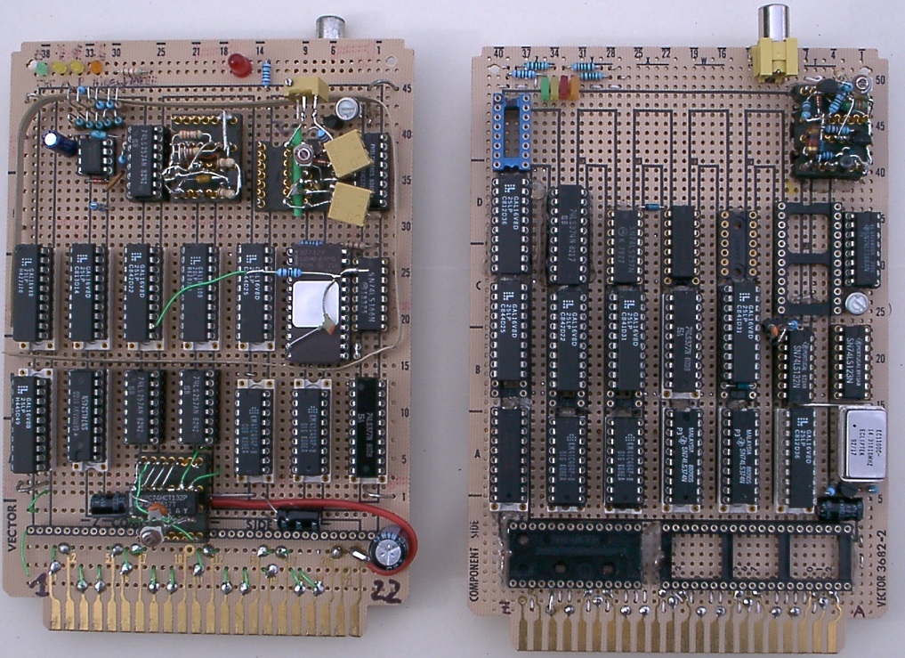
Here is a closeup of the GEN2 (right) and the GEN1 (left) graphics card:
and here is the backside of the GEN2 card:
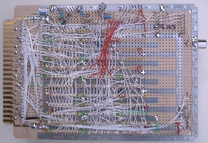
... the bunch of red wires are the bypass of the unpopulated video ROM. These will be removed later, once I have the 74LS258 and the video EPROM.
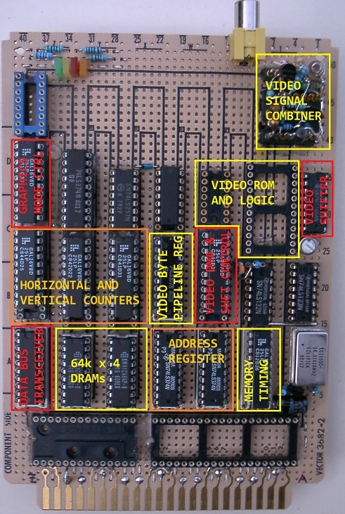
Here are the function blocks of the card:
Here is my Apple-1 work bench:
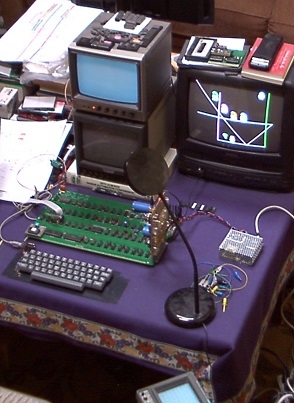
You can see that I use a switchmode power supply (the metal box with holes on the right hand side) which produces exactly 8V to feed the 5V/3A regulator on the motherboard. Linear regulators (like the LM323K) turn excess voltage into heat (actually, the power = voltage drop over them times the current is turned into a temperature rise that depends on the thermal resistance in K/W of the regulator/heatsink assembly) and without any forced air cooling the Apple-1 is not able to handle the extra load of the graphics card when using transformers that have much more excess voltage than the switchmode power supply. Another lovely quirk of the Apple-1 which needs to be taken into account when plugging power hungry expansion cards in.
Here is a screen photo of the test picture seen on the consumer TV in the above photo when displayed on a professional video monitor:
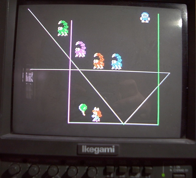
... alas, the photo looks terrible, and the real visual on the screen is much, much better. Seems that my old Y1998 digicam has its limitations when it comes to taking snapshots of pictures on TV screens. With a classic mirror reflex camera using chemical film I knew how to take such pictures. But nobody does that anymore. Another dying technology.
OUTLOOK
So far for today. Y'all have to celebrate Apple's 50th birthday. In the next few weeks I'll continue the work and complete all the functions and tests and then post here in this thread again about the final results.
And then - if there is enough demand - I might design a PCB. The "form factor" of which is t.b.d., but I think a long vertical PCB running along the right edge of the Apple-1 motherboard would look nice. It should not exceed the height of the ACI card, though, because of the many custom made enclosures out there. But any builder who had the foresight to leave a little bit of empty space to the right of the Apple-1 expansion connector should be able to fit such a PCB in.
Comments invited !
- Uncle Bernie
I actually logged on to see if your 4/1 announcement would be here, and believe it or not was wondering if it would be a video related thing, looks cool. Sorry I don't know enough about Apple I to say much more!
Thanks for the detailed description and photos; it looks quite good from the outside. Of course, I’d love to see a ready-to-build kit with gerber files and firmware straight away – I’d definitely put one together. Otherwise, it’ll just become another half-finished project in the ‘someday…’ category. Please don’t get me wrong, I really appreciate your involvement and the effort you’re putting in, but in my view you should consider giving the whole thing a finished look. There’s a huge difference between projects you can only read about and projects you can actually build and use.
Very nice project, I'd like to see it completed, too.
My friend Nino and I did something similar back in 2021, using the TMS9918A (although it's from 1979):
https://www.applefritter.com/content/graphic-card-apple-1
Reference page:
https://p-l4b.github.io/graphic/
The project is open sourced under CC BY 4.0 license.
Boards, schematics, gerbers and code are free to download.
Enjoy!
Claudio - P-LAB
PS in the video the famous "puzzle game" has been obscured on purpose to avoid any copyright issue. ;-)
In post #3, 'macintosh_nik' wrote:
" Of course, I’d love to see a ready-to-build kit with gerber files and firmware straight away – I’d definitely put one together. Otherwise, it’ll just become another half-finished project in the ‘someday…’ category. "
Uncle Bernie comments:
The problem is, as always, the small size of the Apple-1 microcosm. I've explained this many times here on Applefritter: if there are only 2-3 people worldwide who are interested in building one of my projects, then it's simply not worth my time to design a PCB for it. And as I don't use CAD schematics (only hand-drawn scribbled ones optimized for Wire Wrap) I could not hope to give these to some volunteer who then would redraw them in a CAD tool to then go ahead with doing the PCB layout. And so far, no volunteer ever contacted me expressing willingness to spend his or her own time on these chores. Whoever would do these chores and makes a PCB layout could decide to "own" it and try making money with it instead of putting Gerbers on the web. And unless that person is too greedy, this could make sense for everyone involved - for builders of the project, these PCB could be much cheaper to get from that source than ordering a small number from the usual PCB manufacturers like JLCPCB. If you factor in all the costs with packing and shipping, ordering just 3 or 5 PCBs from JLCPCB makes no sense because they end up to be quite expensive due to the small lot size. And then you are stuck with 2-4 excess PCBs to need to sell off somehow, otherwise your one build will get very expensive even when using "cheap" Chinese PCB manufacturers. And I can't do that anyways as I live in the USA, with all the unacceptable tariffs on Chinese made PCBs. The ideal case would be to have "kit providers" who live in nations not having excessive tariffs, and being near other nations with prospective kit builders, to keep postage low. These "kit providers" could also own the programming equipment needed to make the PLDs and the EPROMs. This could help to keep costs low for the individual builder (never underestimate the tools / equipment needed other then the plain Bill-Of-Materials). One such kit source could be in Canada or Mexico to serve U.S. based builders, and one source could be in some country near the EU to serve the builders all over the European continent. It's important that the nation where the kit source lives has no ongoing trade war with the prospective buyers. Or worse, a shooting war, which always leads to sanctions and trade barriers. In the past years, this planet has turned into a madhouse. The recently started Iran war not making things any better. Gas and food prices going up, and all too many people worldwide are struggling with that. Would they rather buy gas and food (if they still can afford it) or buy one of these kits ? Should anyone order a lot of 25-50 PCBs hoping to be able to resell them under these conditions ?
Look, in my long life I got burned too much with investing my time and money into projects which were based on great innovations and looked very promising just to find out, after having invested many man-years and sums anywhere from $250000 to $500000, that the market demand was not there and no purchase orders could be had. Despite during the market research phase, the same potential customers gave the impression that they would love to buy the envisioned product. In the industry, this trap is called "dangling the carrot in front of the donkey". And the stupid donkey was - me ! (and sometimes, my partners in these failed business ventures, too). And don't get me wrong - not all of my business ventures did fail. And I think my success rate was better than the "9 out of 10 tech based business ventures fail" rule which has been around for a long time. Still, I can't afford to own a private jet so I'm still poor and a loser. Because owning and flying around in a private jet is the ultimate measure of success. Worldwide.
Maybe this is because I stopped developing products on my own dime and went into the semiconductor industry as a mere employee aka "wage slave", despite I could have lived well from the interest on my bonds without doing any work on a job. Where the greedy corporation would found my flights of fancy and allow me to try out novel circuits (always a risk). They got the patents for that and some of the products I designed even made them a healthy profit. But not all of the products were profitable - despite they worked fine as specified in the "objective spec". Meaning the product planners also were donkeys who fell for the dangling carrot. Only large corporations can afford such a waste of design ressources, time, and money. It's the nature of the game. Only few semiconductor products ever make a good profit. And the whole history of the semiconductor industry is full of sad stories of companies who never were profitable and soon were swallowed up / sold to larger competitors for dimes on the dollar. Despite these failing companies had great products. MOS Technology with the 6502 processor was one of them. Allen-Bradley (one of the major investors and stock holders) was fed up with the losses produced by MOS Technology and so it was sold off to Commodore in late 1976.
I lived through 50 years of progress in semiconductor technology which was an amazing run but I also saw the failed projects and companies. So I got very, very conservative with investing my own time, money and effort into anything electronic. The projects I publish here on Applefritter are just a hobby for me, to kill time while being retired, to do something useful, and keep my circuit design skills sharp. No intent to make any profit with any of that - and there is no hope to ever make a profit even if I wanted. The marketplace for Apple-1 projects is just too small. And I think that most aficionados in the Apple-1 microcosm see it in the same way. So they don't want to invest much of their own time and money either. They just want ready-to-build "open source" projects for which they don't want to contribute any effort by themselves. Other than downloading it for free and then - maybe - build it. I don't think that all of the 2-3 people who have expressed interest in my projects in the past would really build one, if the files were available.
What I have hoped for this time, being the 50th birthday of Apple, is that more people seek for the topic "Apple-1" and might find to this page and then get interested enough and in large enough numbers (two dozen or so worldwide would be great !) to motivate me to make a PCB layout for this project. I want this PCB for myself because the prototypes occupy the sole slot and are no good for anything other than the development and verification effort as such. But more adopters are needed to add the missing motivation (don't try to "bribe" me with money - for me it's worthless green toilet paper, I already have enough of owning larger quantities of that fraud than I want, but for me, there is nothing out there worth buying and not turning into a burden).
What I will do is to wait. And when not enough demand materializes for an Apple-1 color graphics card PCB, I will turn the prototype into something that might appeal to the Apple II crowd, of which there are maybe 1000 times more aficionados in the world than for the Apple-1. If you look at the photos in my post #1, you can see that I did plan for that eventuality, too.
- Uncle Bernie
The Apple-1 group on Facebook has over 1,000 members, and the parts group has nearly 600. What ‘micro-world’ of the Apple-1 are you talking about?
The problem lies in your approach to the matter. You keep slipping in the phrase ‘I’ll finish it if there’s interest’, but naturally there won’t be any interest until there’s a finished project. This situation is starting to resemble the age-old debate about which came first, the chicken or the egg.
In post #6, 'Macintosh_nik' wrote:
" ... but naturally there won’t be any interest until there’s a finished project. This situation is starting to resemble the age-old debate about which came first, the chicken or the egg. "
The first statement in your comment is not how it works in the real world. For any serious project there is first a market / demand survey to find out if anybody is interested in buying the envisioned project which at this point of time may only exist on paper. This is typical for each and every industry. Nobody will spend resources, time and money, on developing something nobody wants and for which there is no demand. When I post my projects here on Applefritter, this takes the role of the market / demand survey. And as I have very verbosely (may be too verbosely) explained in my post #5 above, even a positive outcome of such a survey does not guarantee any sales, not even one. Potential customers may just feign interest to learn what is out there being "floated" around, maybe to develop a similar product themselves, or file fake patents on the idea to block any patents by the rightful innovator (happened too me, too), and even if their motives are honest, and their interest is truthful, until the product is developed and ready for production, the market may have changed and the interest is not there anymore.
In case of this graphics card this is not about money, because I would only lose the time I would need to invest to design the layout, as the CAD tool I use (DIPTRACE) has long been bought and is paid for. A prototype run at OSHPARK would cost me maybe $100-$150 for three PCBs, and this is not an issue for me, just a bottle of Champagne less. But what I can't afford under any circumstances is to waste any of my precious RQLT (residual quality lifetime) on projects nobody wants. Even if it's only maybe a week or so which would go to waste.
And don't get me wrong - this particular project is very dear to me as I have developed it over 40 years. I started it in Y1986 when I made "first contact" with the Lattice GALs and back then the project was called "GALAPPLE", aiming at implementing a whole Apple II with Lattice GALs, 16V8 and 20V8. It was a very interesting test case for PLD development tools including my proprietary ones. But I never built a GALAPPLE. All I did is the design and simulation. For more, I did not have any motivation nor any time. My own proprietary simulation tools had become so good that it was pointless to build the hardware to prove that it works. The simulation was enough.
After I got sucked into the Apple-1 microcosm, which really is tiny - 1000 members in the Facebook forum, you say ? - I decided to do a few small mods to adapt it to the Apple-1 and I actually built the wire wrap prototypes to prove to potential adopters /builders it's real.
As to the "chicken-and-egg" problem, this is a well known trope, but does not apply here. People could see my prototypes, and comment or send me a PM ('personal message') to encourage / motivate me to make a PCB layout. I won't even take money nor would I want to produce and sell any of these PCBs. But I would absolutely hate if I spend all that effort designing a PCB and nobody wants to build it ? Guess how many people ordered my Gen2 improved ACI PCB from OSHPARK, where I put it up for grabs ?
(Another untold side of my story is how many piles of unused PCBs I have around, all for projects that did not find builders, among these some 50+ (or so) Gen2 improved ACI PCBs which I ordered before the tariffs struck. Every time I see these useless and wasted PCBs I get angry and feel stupid. But I don't want to throw them into the trashcan either).
So, what can we do ?
As I am not going to go to Facebook in any way, shape or form, maybe you go ahead and post a link to this thread there, using your own Facebook account. And tell them to post likes or dislikes (or any other idea how the PCB should look) there, in Facebook. And then, in maybe 2-3 weeks, you can report back to us here on Applefritter how much interest was generated by your post. (I never understood why people a shy to become Applefritter members, Tom Owad does not spy on you nor does he want your name, address, birth date, nor your phone number, Applefritter is much, much safer than Facebook which spies on you and sells all your data (your "personality profile") to third parties, which include organized crime, dubious spook/"Gestapo" type agencies, telemarketing scammers, etc. - this is why I never use Facebook, and for a good reason).
I'm curious how much resonance such a campaign on Facebook might bring. More than the 2-3 people my posts about my projects on Applefritter bring ? Let's see !
Do we have a deal, 'Macintosh_nik' ?
- Uncle Bernie
Perhaps the problem lies in your ‘professional approach’; whilst its principles can certainly be applied to hobby projects, on the whole it’s a completely different matter. In my view, hobby projects generally exist more on a creative level. In most cases, the average enthusiast starts a project primarily to create something for themselves; that is exactly how Woz created the Apple-1. Mike Willegal, Michael NG and Misha originally built their replicas because of a strong desire to own an Apple-1 and a lack of the financial means to purchase an original. Interest in the Apple-1 is not static; there are peaks and troughs. We all remember the last surge of interest in the early 2020s, when it seemed as though the whole world was preoccupied with nothing but building Apple-1s. There were reasons for this surge: Misha published his project as open-source, so anyone could now order a printed circuit board at a low cost; Armin produced excellent reproductions of the original manuals; and you offered the market fully ready-made construction kits, which greatly simplified the assembly process for novice builders. In other words, it is hobbyist projects that are sparking interest in the Apple-1, thereby helping to popularise this hobby. It is the popularisation of this hobby that should be the main objective, rather than the commercial prospects of individual products. That said, if a product is good and attracts a lot of interest, there is nothing wrong with trying to make a profit from it, or at least recoup the money invested.
I’ll certainly post about this graphics card on Facebook, but likes and comments shouldn’t be your main motivation; the main thing should still be promoting this hobby. If you like, I can help you sell your ACI GEN 2 cards; I’ll post an ad in the components group so that anyone interested in buying them can get in touch with you. I’m generally open to any kind of collaboration, provided it’s above board and doesn’t involve prolonged fasting :)
It’s a bit like a young writer approaching Sergei Yesenin with a notebook full of his poems and asking him to assess them and say whether he should even bother with poetry at all. Yesenin didn’t even bother to read them; he said that if you can choose not to write, then you shouldn’t even start — true poets write simply because they cannot help but write.
Hello Uncle Bernie,I made a simple post with a link to this thread.I hope that some of the 1,200 members of the group will come by here.Even though your work only interests a few people, for me it is a form of art that I admire for the simple beauty of the gesture.
Capture d’écran du 2026-04-04 13-16-34.png
In post #9, 'wirehead' wrote:
" Even though your work only interests a few people, for me it is a form of art that I admire for the simple beauty of the gesture. "
Uncle Bernie comments:
Thanks for putting this post into the facebook forum. I really cross my fingers that your post attracts more Apple-1 owners willing to build my color graphics card. If we get about a dozen or so, I will definitely design a PCB for it and make the Gerbers and all the files needed to program the GALs and the VROM available as a tarball.
I like your take that this is a "form of art". I always try to make my designs into works of art, they not only must function perfectly, but also look nice. This is why my PCB layouts require much more time and effort than "normal". And like any artist, I hate the idea that I create something beautiful and nobody cares about it and nobody wants to build it.
So let's see what comes out of your facebook post. Alas, I can't follow facebook myself as I don't want to get spied upon and sold out to crime organisations and/or nuisances (marketers).
I once considered to buy a "burner phone" for cash, with no links to my real person, just to use it to participate in the Apple-1 forum on facebook, but this turned out to be infeasable due to the activation process of such a phone - unlike the various spook agencies who do this all the time, I can't fabricate a fake persona whose data would pass muster. So, no facebook for me. Which is bad as I can't interact with this 1200+ Apple-1 aficionado community there - but maybe we found a way, at least for this project !
I'm really looking for inputs how this card should be specified in its final form, and I'm willing to listen. There are so many options ... such as taking the 14.31818 MHz clock off the Apple-1 motherboard, or providing a DIL-8 or DIL-14 metal can oscillator. Or if the ICs should face to the motherboard, or away from it. Or if the card should have a small fan on it which would blow air onto the LM323K regulator. Or if it should be a modular, dual PCB solution: a basic 48 kByte DRAM card which plugs into the expansion edge connector, and the video section being a 2nd PCB which plugs into the memory card.
And then, the software ... with Microsoft having "freed" their 6502 Microsoft BASIC, by adding the graphics commands to it, a "free", "open source", 100% compatible BASIC could be built.
And who (of the users) would port Apple II games to this graphics card ? (it's 100% Apple II compatible, mind you).
I also have an idea for a "game box" which is cheap and adds joystick ports and sound output to the Apple-1 on a very small budget.
The possibilities are endless !
The only thing that is missing - yet - is a large enough group of interested Apple-1 owners who would build the card and the game box, and port some games. This would be fun, no ?
Comments invited !
- Uncle Bernie
I'm retiring soon and I am willing to build things. A color Video board for a Apple I interests me. :-)
In post #7, 'linuxha' wrote:
" I'm retiring soon and I am willing to build things. A color Video board for a Apple I interests me. :-) "
Uncle Bernie comments:
This made me chuckle ... seems we can only do the fun things - which we always wanted to do - only after retirement. I'm also retired and this is the reason why I can design and build these things now.
Note that "a color video board for the Apple-1" won't be very interesting if it isn't Apple II compatible. My design is 100% Apple II compatible and so it is possible - at least theoretically - to port Apple II games to the Apple-1 so equipped. But this needs volunteers who actually a) build the card and b) port games to it.
Let's see what resonance the campaign on facebook initiated by 'wirehead' of post #9 brings in the next few weeks.
Until then I'll also have the development phase finished and may have some demo software ready.
- Uncle Bernie
I'll gratefully buy one, and help test, if/when they are made.
Thanks and much appreciated.
>> In post #8, 'UncleBernie' wrote:
>>> In post #7, 'linuxha' wrote:
>>> " I'm retiring soon and I am willing to build things. A color Video board for a Apple I interests me. :-) "
>> This made me chuckle ... seems we can only do the fun things - which we always wanted to do - only after retirement. I'm also retired and this is the reason why I can design and build these things now.
I went to school for electronics (they told me all I would do was repair TVs and Toasters, this was befor computers). Somehoe I ended up doing software (QA)
I'll post an off topic thread as to I am retiring, I don't want to steal this thread
On April 1st, 2026, I started this thread by showing y'all a first glimpse of my Gen2 Apple-1 color graphics card, still some components missing, which in the meanwhile were ordered, received, and installed, and it worked !
GEN2_in_Apple1.jpg
Here is a closeup of the TV picture seen in the above photo:
GEN2_charset.jpg
The "shade" effect seen in characters $40-$7F is due to the flashing effect of these characters, one of the features the original Apple II also had. It took me a lot of attempts hitting the button on the camera at the right time, until I got this effect !
Note that unlike the early Apple II, the GEN2 Apple-1 graphics card also has lowercase characters and the all important characters (such as the curly braces) from ASCII $7B to $7E (Apple text screen codes $FB to $FE). The DEL / RUBOUT character is rendered as a shade made from a checkerboard pixel pattern. This was first seen in the Apple IIe, I think.
It was not a mean feat to squeeze all these character sets (along with the LORES and HIRES graphics dot pattern translation tables) into a period correct 2716 EPROM, which only has 2 KBytes. Even the bright engineers at Apple who designed the IOU custom LSI chip were not able to do that squeeze. They needed a 2732 having 4 KBytes. But although the 2732 was available in Y1978, it still was very, very expensive, about 4 x the price of the 2716. This is why the 2732 was rarely used in Y1977/78. Its sales took off in the early 1980s, after it became cheaper, and then even the Taiwanese Apple II clone makers switched from the 2716 to the 2732. Ironically, the 2716 is harder to find today while the 2732 is abundant, and was in active production until the the end of the 1990s. Possibly due to its enormous popularity in industrial control equipment. Here is a photo of the finished 'lab rat':
GEN2_MMI_Top.jpg
You can see that all the reprogrammable Lattice GAL16V8 which were used in the development phase were replaced by fuse link MMI PAL16R6, and that the character generator and graphics translation ROM was implemented by a type 2716 EPROM (c) Intel 1977.
OUTLOOK
Thanks to the effort of 'wirehead' with posting a link to this project in the Apple-1 facebook group (see his post #9 in the present thread above), this project finally got enough "YES" and "likes" to justify making a PCB layout. I've already started to take measurements and make a cardboard mockup to plan the PCB form factor.
But much more work needs to be done to turn this into a DIY project which can be built by other Apple-1 clone owners. Just making one wire wrapped prototype of anything is easy - all the characterisation measurements, tests and mods needed to turn it into a "product" (even if it's not a "real" product, as YOU have to build it) may take more than the two months it took me from the launch of the GEN2 design to the finished prototype seen in this post.
The biggest challenge with this project is how to handle all the quirks in the Apple-1 itself, such as its often rotten / ringing signals and its evil scrambling of the addresses on the bus whenever the on-motherboard DRAM is accessed. I have developed and tested several solutions for each of these issues but before I can decide which alternative solution to adopt, I need to do extensive and time consuming testing on all my remaining dozen Apple-1 builds - each of them being slightly different. Now I'm glad that I was too lazy to sell them off. Otherwise I would not have the test platforms needed to qualify this GEN2 color graphics card design. Oh, and I will need beta testers, too, once the PCB layout is finished.
TENTATIVE COST ESTIMATE FOR BOM
I expect a BOM of around $30 if no IC sockets are used, plus the cost for the PCB, which thanks to Trump's tariffs on Chinese goods can turn out to be very expensive. I'm currently exploring ways to source PCBs from alternate Asian makers, such as from Taiwan, Malaysia, or Vietnam. But the problem with these sources is that they typically are not geared to make small prototype runs for hobbyists. Still, on the long run a solution must be found. Too many of my projects for the Apple-1 and Apple II got stuck due to the loss of JLCPCB - prior to the tariffs, they had great prices even for small fabrication runs. For instance, the PCB for my YAAK keyboard did cost $6 each, including shipping. If made by OSHPARK here in the USA, the naked YAAK PCB would cost ~$150, each, and you have to take three of them. This is why nobody (even me) wants to build a YAAK, as the naked PCB "Made in the USA" alone costs more than what the whole BOM of the complete keyboard kit should cost. Makes no sense to waste our hobby budgets on any of that. We must find a good and cheap PCB source before we can proceed.
So far for today ! (I'm in a hurry). I'll post more about the historical background and the "period correctness" of this design in the next days. Feel free to ask any questions on this project in the meanwhile.
- Uncle Bernie
I do not own an Apple 1 or replica, but this is very interesting stuff, always nice to see something old made new again with things it was never designed to do.
In post #16, 'Khaibitgfx' wrote:
" ... always nice to see something old made new again with things it was never designed to do. "
Uncle Bernie comments:
Actually, the Apple-1 was designed in such a way that it could be upgraded to NTSC color graphics, at least this is what Woz himself tells us in his autobiography "iWoz", and I think I could add color graphics to it by just adding a few gates to make the "color burst" signal and by replacing the character generator ROM with an EPROM which has color translation tables. The video counter / timing chain on the Apple-1 motherboard is perfectly fit to do NTSC color graphics. Really looks as if it was designed for this purpose.
There is a catch, however: the Apple-1 has a shift register screen buffer memory which does not allow "random access". And so no graphics "action" games could be made despite colors as such could be had. The simple add-on color graphics system would need to sacrifice some characters for colored block graphics the size of a character. And this is all which could be had.
I think that Woz did see these limitations himself, and so he never implemented such a limited graphics system for the Apple-1.
But I have a hunch (call it a hypothesis) that Woz might have experimented with adding the color burst signal to the Apple-1 and once he had it (this needs only a few gates, the TTLs for that could be put into the prototype area on the Apple-1 motherboard), he could see that all the characters on the screen got colorful, even with the Signetics 2513 character generator. These artifact colors (as they are called) may have given him the inspiration how the HIRES graphics mode used in the Apple II works. At minimum, this would have been a quick "proof of concept" for HIRES graphics which would not need more than a few hours of work for adding the gates to the Apple-1.
I think that the "weird" ways how the Apple II generates LORES and HIRES color graphics had to be tried out experimentally before the wire wrapping of the Apple II prototype started. They are just far too boldly abusing / bending the NTSC concept to be adopted without trying them out on a real TV. And the Apple-1 could have served as the test platform for these experiments.
Of course, Woz could have built the video counter and timing signal chain of the Apple II "lab rat" independently from the Apple-1, but so much of it was copied from the Apple-1 that it is almost the same functionality. So it would have been logical to hook a few makeshift color circuits to the Apple-1 to test the viability of these concepts quickly and without much expenditure. Once you have added the color burst signal to the Apple-1, you can unplug the 2513 character generator and feed bit patterns made by static wires (or mouse pianos) into the 74166 video shift register to emulate HIRES mode. Hook the clock of the 74166 to the master oscillator (14.318 Mhz, twice the DOT CLOCK) and you can fully explore all the LORES graphics colors. So in just one afternoon of lab work, all the "weird" concepts of Apple II color graphics could have been explored and verified on the Apple-1.
So far my conjecture about how the Apple II graphics modes might have come into being.
- Uncle Bernie
The 41464 DRAM chips, especially the 80nS ones, are "period incorrect".
In post #18, "transwarp2" wrote:
" The 41464 DRAM chips, especially the 80nS ones, are "period incorrect". "
Uncle Bernie comments:
Ah, my old nemesis 'transwarp2' has finally decided to poop into my threads again, as he/she/it has nothing constructive to contribute to the Apple-1 world anyways.
If you, 'transwarp2', are a complete fanatic who insists on 100% "period correctness" then dump your Apple-1 clone you may have built into the trashcan because the PCB can't be "period correct" as it does not use manually silk screened solder mask (and has other manufacturing process differences, too, which are not 100% "period correct") and go ahead and buy an original Apple-1 which then certainly is 100% "period correct". But I suspect you are too poor to buy one of those. You may not even have an Apple-1 clone at all.
My use of 64k x 4 DRAMs for this graphics card is deliberate to keep PCB area and costs down. This is a very pragmatic approach which does not hurt the "period correctness" of the circuit design itself. The design was done such that it could use 2nd Generation 4k x 1 DRAMs which were available already in Y1976. It is possible to take the 64k x 4 DRAMs out of their sockets and use DIL adapters to put on a mezzanine PCB having 100% "period correct" MK4027 DRAMs on it. To get the 8k bytes minimum needed for Apple II style HIRES graphics, 16 such MK4027 are needed. The PCB area for that minimum RAM would be larger than the whole current PCB layout itself and the costs for the graphics card build would double. For the 48k bytes the easily and cheaply sourced 41464 DRAM ICs bring to the Apple-1, 96 pieces (!) of the MK4027 would be needed. The PCB size would be larger than the Apple-1 motherboard itself.
My standpoint is that due to economic viability for the typical builder, reasonable concessions must be made as to the choice of IC components for such projects. Sure, I could implement an Apple-1 color graphics card the size of the Apple-1 motherboard itself, just to prove my point that my circuit design would work with these 4k x 1 DRAMs, but noone being sane of mind would want to build one of these, they just would be too expensive and awkward.
If you doubt the truthfulness of my claim that MK4027 4k x 1 DRAM would work in my design, just look at the Apple II manual of 1979, which still showed how the Apple II motherboard can be populated with generic type 4096 or 4027 DRAM ICs, all 4k x 1, and this would have yielded 12 kBytes of RAM in the whole machine. Woz designed the Apple II for that. Because he started that design in late Y1976 (most sources say it was in December 1976). The CPU cycle timing of the Apple II is exactly same as in the Apple-1. Even the scan line timing is the same (65 CPU cycles per scan line). There can be no doubt that Apple II style color graphics could be implemented using these generic type 4027 DRAM ICs. It's just a matter of how many such ICs people would want to solder in to get those graphics. The DRAM timing as such is exactly the same, whether the 4027 or the 41464 is being used. The latter are faster, sure, but this speed is not used in this design.
- Uncle Bernie
Hi Fans -
I was working in a PCB layout for this project for a while. It is almost done but space is running out. See here:
GEN2_graphics_PCB.JPG
The original intent was to make a PCB that is the same length as the Apple-1 motherboard is deep, and then, a small 40mm x 40mm fan would fit nicely at the right spot where it can blow cooling air into the heatsink of the LM323K regulator, and also blowing the air by the three TO-220 regulators located downstream.
Note that adding this fan is NOT necessary as long as the Apple-1 with the graphics card runs from a modified switchmode power supply which feeds the LM323K with 8V. But for those who use the prescribed transformers seen in the original Apple-1 manual (or equivalent transformers), the LM323K runs with ~10V and so it has to turn half the power consumption of the whole 5V rail into heat. This can be done without active cooling by a fan but it's not really healthy, as the LM323K gets very hot and it will sizzle and draw blisters on your fingers when touched.
So for those builds using transformers which run the regulators with excessive voltage headroom, adding that little fan is recommended, and it fits nicely on the PCB --- if you live outside the USA, you will be able to afford the extra PCB area without any financial stress. But since Trump's tariffs on Chinese goods, this is no option for residents of the USA (like me). In this case, the PCB must be ordered from a domestic manufacturer such as OSHPARK, and they charge $5 per square inch. You get three PCBs for this, but still, I consider adding the extra PCB area just to mount the fan is a waste of money. And I loathe wasting money, despite I am not exactly poor --- and last but not least, I want my projects to be as cheap to build as possible, so no prospective adopter would be turned off by excessive costs. This is the reason why I deliberately used 64k x 4 DRAMs. Not to "cheat", but to keep PCB area and costs reasonably low. At much higher PCB area and much higher costs (maybe $1000 more or so), this same graphics card design could be built using 96 pieces of 4k x 1 DRAMs. Which, due to these excessive costs, nobody would want to actually build. Still, it's a nice thought experiment to figure out how large that would get if 4k x 1 DRAMs were used.
TWO PCB VERSIONS
I decided to make two versions of the layout: a long one for those builders living outside of the USA who can order PCBs from JLCPCB without the tariff penalty, which has the fan, and a short one for those builders living in the USA, with no fan.
And for the latter version, I ran into trouble: as you can see in the above photo, in the lower left hand side corner, space is running out for the video mixer and the video output stage. I already had to "cheat" a bit, using very small SMD components hiding below the address decoder IC, to implement the color burst killer circuit for TEXT mode.
(I do not consider this "cheat" to be an offense against period correctness, because resistors and transistors did exist back then, in 1978, and earlier, with the same values, but they had much larger packages. Other than the package size, there is no difference. )
Note that it's not only the three components seen in the photo which don't fit, actually, there are fifteen (!) such components which don't fit and have not been instantiated yet - I do this layout without any CAD schematic, because a rigid CAD schematic would lead to suboptimum layout, and of course, NO "autorouter", and NO "AI" could ever make auch a dense layout on a period correct two layer PCB where you can't run two traces between pads because the PCB manufacturing technology back then would not allow that. But I use layout tricks most people don't know that these tricks exist - "bending" the circuit on the fly as I need it for the layout to be optimally dense. This is why CAD schematics are useless for me. They just would slow me down and cause less dense layouts.
OPEN QUESTIONS
OK, now here is the question for you: I am inclined to realize the whole video mixer and the video output stage in SMD, except for the few components for which no SMD versions exist. This part of the circuit will be built on a break-off PCB section which comes from the upper right corner of the PCB ... this cutout is necessary so you can still use the ACI card and plug in its audio cables. You see, I took care of everything. Actually, I made a cardboard mockup of the whole PCB with a glued in real 44 pin EDAC connector, just to get the mechanical clearances right.
I think if the SMDs are hidden from sight by mounting the PCB piece carrying them upside down, there will be no visible offense against "period correctness". Same philosophy I used to do the "Gen2 improved ACI" where all the extra circuitry was implemented by SMD components hidden from sight by placing them under the DIL socket. But I did make sure I only used components which did exist back in Y1976 function wise, but, alas, in a much larger package. 50 years ago they had no way to make these small SMD plastic packages. Now we have that packaging technology. And this was THE opportunity fo me to "hide" the extra functions needed for the Gen2 ACI. So for the casual observer, the improved ACI still looks the same as the original, botched circuit.
Comments invited !
(I will put the PCB layout on hold until I got your feedback).
- Uncle Bernie
Hey Bernie, I think this project is awesome! You're doing a great job again! I'd stick with the SMD components. A little compromise is okay. Better to have hardware that works well than a piece of visual history. Looking forward to more updates
Hi fans -
today, the PCB layout for the graphics card was finished, except for the final verifications ... as I did the layout without CAD schematics so I could "bend" the circuit on-the-fly, necessary to make this beast routable, but the downside of this method is that there is no schematic which could be used for LVS. So LVS must be done by hand, as it was done for IC designs some 50 years ago. This is called "progress", folks !
Here is the current state of the PCB:
A1_graphics_PCB.JPG
You can see this is the "short version" without the cooling fan to keep area and costs as low as possible - if I made a mistake in the routing, throwing $100 (or so) into the trash can hurts less than throwing $150 (or so) into the trash can.
I was able to avoid to use more SMD components by standing some small resistors and diodes upright. This is the same technique which was used in cheap, small transistor radios from 60 years ago. A trick which fell out of favor when machines replaced the human hands which had put the components into the PCBs before the machines could do this. For hobbyists it's still a viable method to stuff PCBs.
Note that other than the 44 pin connector, all the components are on the back side of the PCB. This is necessary to make the whole thing fit together with various enclosures I have as specimen. The cutout in the upper right corner is for the audio cable plugs of the ACI.
Cross your fingers that this PCB layout works ! It's very crowded and if any mistake has been made, it is unlikely it can be fixed.
- Uncle Bernie
P.S.: Arnaud of POM-1 fame has volunteered to put a 100% emulation of this card into his POM-1 Apple-1 emulator, see this thread:
https://www.applefritter.com/content/pom1-apple-1-emulator-cycle-accurate-c-rewrite-50th-anniversary-and-modern-development
... Which means that in the near future, you will be able to develop software for this card using POM-1, including all the features like the special flag I've added to allow software to track VBLANK and HBLANK events on the card. A much more powerful hardware feature than the VBI flag seen in the Apple IIe and IIc. I think (but have not demonstrated this yet) that using this flag, not only vertical screen splits at any scan line would be possible, but also horizontal screen splits, for instance, columns of text alternating with columns of LORES graphics. Which would be useful to make a "color peg" version of my "Codebreaker" game. We all know that HIRES graphics can render the same character set as TEXT, no problem, but it only has four colors available plus black (background) and white (useless for the game).
Great job, can't wait to get my hands on a PCB and build one.
In posr #23, 'Sarnian' wrote:
" Great job, can't wait to get my hands on a PCB and build one. "
Uncle Bernie has some news:
The manual LVS was completed this morning and only a few "bugs" were found: components which are on the PCB but somehow never made it into the scribbled "schematics" I made on-the-fly while doing the layout. These components were wired correctly, though. What I could not check is if there are any shorts ... DIPTRACE, like many other PCB layout programs, can't "see" shorts caused by stray vias or stray trace fragments in all cases. But it does "see" shorts caused by copper pours. Strange.
I've uploaded the Gerbers to OSHPARK to see if there are issues. Here is the rendering of the PCB by OSHPARK:
GEN2_graphics_OSH.JPG
Note that the "Top" side is where the connector is soldered in and this is the otherwise naked side visible from the Apple-1 motherboard's point of view. The silk screened legends are meant for debugging / measurements / IC types. All components other than the connector are on the "Bottom" side but it is so crowded that the silk screen can't be read anymore after the components have been soldered in.
You can spot where I had to "cheat" a little bit by using SMD components, but they all are hidden below an IC, and kept out of sight once the card is populated:
On the left hand side is the 74LS166 video shift register in SMD, hidden below the video ROM. This is inevitable as there is no way to put a full size DIL-16 IC in the vicinity of the VROM. The cutout which is required for the ACI audio cable plugs "stole" away the area which would have been needed for the full size 74LS166.
And in the the lower right corner there are a few very tiny SMDs which kill the color burst in pure TEXT mode. That circuit grew from one transistor and one resistor to two transistors and four resistors. So more space was needed.
The whole card is only 166 x 71 mm in size and it follows mid-range process technology design rules for trace width and spacing, which were typical for Y1976. This is a self-imposed limitation to keep the PCB itself "period correct", despite there of course are some "cheats" like the SMDs. But if you have a time machine, you can travel back to Y1976 and have these PCBs produced on a typical PCB manufacturing process of that era. Don't forget to bring with you a stash of these SMDs and a bunch of MMI PALs. These became commercially available in Y1978 but MMI had found out that they could not produce them in any useful quantity. Which also jeopardized Data General's "Eagle" project (the Eclipse MV/8000) which was started in Spring 1978 and depended on those MMI PALs to be available in quantity. Early MMI PALs came only in 20 pin packages and were the PAL16L8, PAL16R4, PAL16R6, PAL16R8 family. From my memory, so take this with a grain of salt, they (MMI) intended to sell them for $2...$3 each but they had to take $50 for the few functional samples they could make before the issues in the wafer fab were sorted out and yields became acceptable. $50 in Y1978 is equivalent to $230 dollars today (Ouch). In the same year, the 2732 EPROM was advertised in BYTE Magazine for $39.90 each ... $204 in today's dollars - even more "ouch" ! This is why i n Y1978, everybody still used the 2716, like this graphics card does. But it can be upgraded to 2732 so a manual switch can choose between two different character sets (you make them, I'll only provide the 2716 binary).
PRICE
OSHPARK quotes $91.35 for a set of three, so each one costs $30.44, which is only 44 cents over my cost target. Still, it is very expensive for most hobbyists. Because what can you do with the surplus two PCBs ? Sell them to other hobbyists ? --- I think this will not fly, because there are only a dozen or so member of Applefritter and the Apple-1 facebook forum (which has 1200 members) who have responded with "YES" ( = "I want to build one").
I will do some final cleanup work on the copper pours, re-run the DRC, and then order a set of three from OSHPARK.
Hopefully they don't take too long and cross your fingers that they will work !
I'll keep you posted about the progress (or lack thereof).
- Uncle Bernie
Here is another option for US customers: make them in China and sell them through MacEffects. They are the primary US distributor for my card and I am very happy with them. The fees are very reasonable and the payments to me are always on time. Mark is the owner. He sold several batches of my card already and is very honest and punctual. If you don't know him, you know Jonathan Adar, who can make the introductions.
Here is what we can do, if you are interested and Mark agrees of course: I can order the PCBs from JLCPCB, have them shiped to Bulgaria and then ship them to Mark. Since your PCB is almost the same area as the Dan ][ Controller, I did some estimations using Dan's gerbers and it looks like the sweet spot is for a batch of 30:
JLCPCB.png
Assuming that each PCB weighs 40 grams (based on the Dan ][ Controller once again) to ship a 1.4 kg package from Bulgaria to Mark in the US will cost an additional €29.34 + €8.90 for prepaid tariff and fees for a total of €38.24 = $44.19. This brings the grant total cost for 30 PCBs to $71.70 + $44.19 = $113.89.
If Mark agrees to this, you guys can figure out a price and how he is going to pay you. I don't need a fee for this, since Mark has sold a lot of my cards and charges me very reasonable fees. Instead he can pay my expense whenever he sells them, which is the same as the standard deal we have when he sells a batch of my cards.
In post #25, "CVT" wrote:
" Here is another option for US customers: make them in China and sell them through MacEffects. "
Uncle Bernie comments:
As much as I appreciate your inputs and hints how to deal with the unacceptable PCB situation for USA based hobbyists, CVT, this is not the way I want to deal with this. The shipping costs would double and exceed the costs of the PCBs themselves. Makes no sense to me.
Oh, and it's too late anyways as I have already ordered a prototype run of 3 at OSHPARK. Just to find out if they work ... circuit bending while doing layouts has its risks. I would hate the idea to order 30 pcs and then throw them into the trash. Even if the 30 pcs would cost the same as the 3 pcs from OSHPARK. It's about avoiding waste. I have great psychological barriers to throw things away and I'm still sitting on stacks of unused PCBs for various projects which I have accumulated over the decades. Every time I "rediscover" one of these stacks, I get angry because I see the wasted time and effort that was put into making them. But if I threw them away, then I would regret it, too, as I might need to build one of those projects later, if I can't find the one specimen that was built, or if it gets blown up in the lab.
Same happend with my BYTE Magazines which I threw out about 30 years ago and then, for my work on the Apple-1, I had to buy them back on Ebay, for very high prices. Nothing is a greater embarrassment than to have to buy again some object you have thrown away because you thought it's of no use anymore to keep it. Lesson learned !
But there is no doubt a good solution must be found when the project is finalized. Same for the PALs/GALs and the 2716/2732 EPROM which must be programmed. No every hobbyist has suitable programmers.
Furthermore, the PCB layout is not complete yet. I want to use the area that had to be taken out for the access to ACI connectors as a "break out" small bonus PCB which serves some useful function. That useful function has not been defined yet ... I might need it for improving signal quality on the Apple-1 motherboard. Or for the alternate "flashing" circuit I have explored. Or for my A2A1 keyboard adapter PCB ... the possibilities are endless. But whatever I choose to put into that available area, it must be useful for the typical builder of this graphics card.
Last but not least, I must also make the "larger" version with the fan and it's power supply electronics. This is still not finalized as it requires a lot of experiments to explore the options. There are so many small fans out there, some even have PWM speed control. I don't know yet if that would be useful. It has to be tried out with installations of the PCB in actual enclosures. And it's tricky as there are two different sizes of the Apple-1 motherboard around. The solution must fit both.
So, stay tuned ! I'll report here on the progress of the project. Ran into some problems recently, another parallel printer port was blown up while serving as the Apple-1 keyboard. I have yet no clue why this happens, how can a PIA input from the Apple-1 blow up a LPT output in a notebook ? I now have a whole pile of notebooks with damaged printer ports and none are left. And so I can't download my graphics card demo software anymore into the Apple-1, and the recent change of the soft switch addresses to avoid conflict with the ACI rendered the current version obsolete. Of course, over the next few weeks, the PCBs will arrive, I can build an example, and if it works, I can use the Apple-1 together with the ACI and the graphics card, and then continue the development of the software.
The bottom line here is, this project is far more complex and time consuming as it seems. Developing such a wire wrapped 'lab rat' into a sort of "product" which hobbyists could build with some resonable chance of success requires a lot of extra work. BOMs and building instructions must be written. And there should be some driver software available for all the plotting, drawing, and for 'sprites'. A lot of work to be done !
I hope it's worth it.
- Uncle Bernie
Oh, I didn't mean that you would do this during the prototyping stage. This is for once everything is finalized and ready for actual users. I understand your point that the cost of manufacturing the PCBs becomes less than half of the total cost, but it still brings the cost down to under $4 per PCB, while a reasonable retail price in a store like MacEffects would be at least $25 in my opinion.
Anyways, my offer stands in case you don't end up finding a better solution for US customers and change your mind.
UncleBernie, In case I haven't responded, please add me to the list of builders. Thanks!
In post #28, 'macnoyd' wrote:
" In case I haven't responded, please add me to the list of builders. "
Uncle Bernie comments:
Thanks for your interest, macnoyd, but there is no "list of builders". I could not contact most of those who have expressed interest in building this graphics card on "facebook" anyways. The thread there was initiated by 'wirehead', see post #9 above, on his own initiative. But it generated enough responses that I could justify the 3 weeks of work to actually design a PCB layout for it. It's not 3 man-weeks, though. I worked only 2-3 hours on it, after breakfast, every day since the decision to do it was made. So I'm not as inefficient and slow as the "3 weeks" seem to imply ;-)
Here is a rough outline of my plan:
Once I got the three prototype cards from OSHPARK, I will build one up and see if it works, which will take about a day, because I must revise all the PLD designs for the new pinouts used on the PCB. If it works, I'll use another card to snap photos of the building process and write a 'builder's manual'. After that step, I need a beta tester owning an Apple-1 clone and living in the lower 48 who will test if it can be built by people other than me. I'll provide this as a parts kit with the PCB at cost, and will help if something goes wrong or does not work. This is just to test the building manual.
After that I'll release the Gerbers and JEDEC files to the public. Not sure if I have the time to provide IC kits for those who have no PLD programmer. Or complete kits with all components including the PCB (which must be sourced from a place not affected by the tariffs and still be affordable for hobbyists).
For me it's tempting to make complete kits just to get rid of my excess parts stock left over from this project. The problem, as always, is that buying the components just for one build is economically stupid because the "sweet spot" for the pricing at distributors is with the higher numbers like 25, 100 pcs of te same component. They do sell almost everything at qty 1, too, but then the prices are much, much higher, due to the handling and packing costs (it costs the same to put 10 resistors in a bag as putting 100 or 250 or 500 of them in). So I always order components at quantitities where the "sweet spot" is ... and then it most cases, can't use them up for other projects.
Any hobbyist out there faces the same problem. This means that for any such hobby project, the costs for procurement of the components will be much higher than the plain BOM would suggest.
So it makes sense that hobbyists team up and one of them make a group order and then distributes the components to the team members. Which, of course, also may incur postage. USPS small parcels now cost $8 (or more) to ship within the USA, twice (!) of what it was in Y2019. USPS also wants to treat bubble mailers as small parcels. Theoretically, you could pack a kit as a "flat", i,e. a cardboard envelope, as long as it fits through the slot of their size test panel, but what if the components inside get squashed so badly that they become useless due to bent pins ? I once sent PROMs for the Apple-1 in small clear plastic jewel boxes in such an envelope and got them back in a plastic pouch, completely flatted and destroyed, with the sticker on the pouch, "We care". Sure. They should have paid me for the loss. Only then their "We care" slogan would would be no lie.
So, Houston, we have a problem. In the past 7 years or so, postage got so expensive that it makes no sense anymore to send cheap components to anyone, as the postage may exceed the value of the components. But PCBs still could be sent around as a "flat" just protected by one of these cheap mailers made from thin grey cardboard you can buy at Walmart. Alas, the trick is how to source these PCBs without falling prey to the tariff ripoff artists and their "handling fee" scam.
All these shenanigans foisted on us by anonymous bureaucrats and corrupt politicians bought and paid for by big corporations (who seek to destroy independent "makers" and small businesses, as they want us to buy their overpriced and low quality crap products infested with spyware and backdoors instead) can be dodged with enough time and effort and energy being spent on dodging them, but the big question is if its worth the time, effort and energy to do so. Not everybody can "Go Galt" and stop producing for all these parasites and leeches, and there is no "Galt's Gulch" where independent producers can freely exchange their products and services to likeminded, freedom loving individuals. I spend my evenings now with reading through the early BYTE Magazines, paying particular attention to the ads from small businesses and the component prices. These early years of the microcomputer revolution were great. The rule was "anything goes" and "there are no rules". These were the best years of my life !
- Uncle Bernie
UncleBernie, I get it, and I largely agree with your comments, but at some point, we all have to deal with cost, postage, tarrifs etc. or do without. Change is ineviable, especially in the tech field we're in.
Postage has gotten crazy expensive. Fuel too. You otta see what we pay to heat our homes in New England. I'm just glad the tax on it isn't like CA. We'd all freeze here, LOL ! ...
PCB manufacturing has taken a similar route. You'd be lucky if the board manufacturer you choose doesn't share the design with someone in China or Hong Kong. I've seen it first hand. But I digress ...
I and others who share interest in this project realize the cost will often be elevated at the build level for a veriety of reasons. Some will buy, some will not.
It depends what the cost is and what the value is to the person interested. I understand where you're coming from on a personal level, but I wouldn't worry too much about it beyond your own interest.
I see guys in car clubs who own cars that exceed $250K, yet they complain like they're going broke when the Club they're in raises the cost of club dues by $25. You get my point.
With regard to parts that are difficult to obtain like PALs, PROMS or other programmable devices, we'll all have to find alternatives at some point in time. It's already started a while ago.
I appreciate folks like yourself that keep vintage Apple 1 & 2 computers alive with innovations like this and hope you never get discouraged when the environment around us feels like they're bleeding us dry.
Thank you for your time and efforts. I'm sure many here appreciate that, including the more silent ones, like me.
... for the PCBs. Expect them in the next few days. Cross your fingers that the layout has no bugs !
Stay tuned !
- Uncle Bernie
Hey Bernie,
I hope it will work immediatly. I'm interested to support your tests. Maybe you send a plain pcb to germany too.
Or I have to wait for the Gerber files. Good luck!
best regards
Hi fans:
earlier this week, I got a parcel with the components for the PCB version of this graphics card, and yesterday the first prototype came alive:
A1_GRACARD_PCB.jpg
The prototype PCBs were made by OSHPARK, hence the purple color of the solder mask. To fit the Apple-1 motherboard, it should be green. Note how the ACI card with its audio cables fits nicely and does not clash mechanically with the graphics card. Also note how the graphics card extends below the Apple-1 motherboard - there is no other way to fit all the components on the card otherwise, so you need to have "feet" on your Apple-1, which is well advised anyways as feet or standoffs prevents short circuits from metallic debris on the table surface.
IT WORKED ON FIRST POWERUP !
Everything worked upon first powerup, except for the colors being wrong - a totally unexpected surprise. The magenta/green was swapped with orange/blue. This means that the color burst phase was off by 90 degrees. This was NOT a mistaken PHASE bit used in HIRES graphics because the LORES colors also were wrong. I had to rewrite the BURST signal equation to get the correct colors. Hmmm ... so far the actual root cause is not known and needs to be investigated. What I know for sure is that it's not a wiring mistake in the PCB. No errors were made there - not a mean feat for doing the PCB layout without any CAD schematic, and hence, no LVS, all while shuffling IC pinouts on the fly to get more optimum routability.
There also are a few cosmetic / mechanical flaws which need to be fixed (if possible at all): one oval pad hole turned out to be round and some vias hit the silkscreened legends on the solder side, despite the text was carefully placed to avoid the effect.
Still, I'm not disappointed, but to achieve perfection, a 2nd prototype spin for the PCB is needed, so be patient.
Here is a closeup photo:
A1_GRACARD_PCB_closeup.jpg
Note how densly the PCB is populated. This is about the maximum density possible with a two layer PCB using period correct design rules (like trace width and spacing). I did not want to "cheat" here, and I do have very fond memories of the TTL based computer PCBs I cannibalized for TTL ICs when I was an early teen. The only PCBs I got at this time which had denser routing were from "Big Blue" (IBM). I got some of them, too, but could not cannibalize them, as the "Solid Logic Technology" modules on these cards were elusive, no documentation to be had. I opened a few of these aluminum cans and found hybrid circuits. This was 1960s technology for the IBM System/360 mainframes introduced in Y1964. So in the early 1970s, the bad cards could be had (a friend's dad worked as an IBM service technician, but as I said, the SLT modules as such were useless for us - much more helpful was our use of his company furnished oscilloscope on the weekends).
Here is the backside of the PCB based prototype:
A1_GRACARD_backside.jpg
Note how the silkscreen legends help to get the right ICs into their sockets ... on the component side there is no room for these legends to be seen on a fully populated PCB. The cutout on the upper right corner is for the ACI audio cable plugs.
This is the "short" version of the PCB. I will design a "long" version, too, which extends the full length of the Apple-1 motherboard and has a small 40 mm x 40 mm x 10 mm fan cooling the heat sink of the LM323K regulator.
It will be your choice which version to use. I will provide Gerbers for both the short and the long version. But the long version will be designed such that it could be shortened to the short version by means of a saw. So it is not necessary to have both versions ordered, which helps to make group orders more economically viable.
SOFTWARE DEVELOPMENT KIT ALREADY AVAILABLE !
Now, if you want to start writing color graphics software for your Apple-1 without having this graphics card yet, here is a complete SDK available which includes an Apple-1 emulator that can be configured to have the card:
https://www.applefritter.com/content/pom1-dev-apple-1-cc65-sdk-2026
PLANNED FUTURE TIMELINE
I think it may take a few more weeks, if all goes well until late September / early October, before I can release the builder's tarball which contains the Gerbers and the JEDEC files to program the PLDs and the EPROM. Oh, and not to forget: I also need to write the building instructions and Bill-of-Materials. Maybe it will become early November before all this work is done.
Before releasing the tarball, I first want to go through two beta test phases:
UPCOMING BETA TEST PHASES:
Beta test phase 1 (in USA only):
I'll ship out a few readily assembled and tested color graphics cards to see if the typical Apple-1 owner can successfully install them on their Apple-1 builds.
Beta test phase 2 (worldwide):
I'll ship out a few kits for the color graphics cards which will have 100% tested and burned-in IC sets along with all the other components. This is to see if a typical hobbyist can build them. For me, the few small SMD components can be soldered by hand, but I do have the fine motor skills of a watchmaker (another hobby of mine). I fear that for some builders, the 0608 sized resistors and SOT-323 transistors may be a bit too difficult to solder by hand. Let's see if these concerns are justified. If so, builders need to team up so they can order PCBs with the SMDs already installed. Many prototype PCB houses (like JLCPCB) offer services to do that, buy this incurs extra costs for the solder paste stencil and the programming of the pick-and-place robots. The SMD components as such are very common type and certainly are in stock at any such SMD assembly facility.
TIME LIMITED CHANCE TO BECOME BETA TESTER IF YOU ARE LIVING IN THE EU
Alas, I can't send any PCBs or kits into the EU anymore, due to the obnoxious customs dictats put in place by the Brussels EU dictatorship and now being fully enforced. The worst roadblock is RoHS conformance, but it's impossible to document that for vintage components which were made decades before RoHS legislation even existed. And more recently, it also seems to be necessary now that each and every loose component in a parcel must be a line item on the customs declaration, along with the "harmonized customs code". Imagine the customs paperwork for a kit with 100 (or more) loose components. Making the EU customs declarations for a kit worth $60 might cost $1000 (or more) just for the dictated elaborate paperwork no custom officer will ever read, but insist on the paperwork being there (looks like a "make work policy" even if the work is nonsense and unproductive, typical for failing nations). Paperwork which must be done by a professional having access to the software. Madness !
So, sorry, I can't ship any kits from the USA to the EU, but I have a plan for those Apple-1 aficionados living in the EU who want to become phase 2 beta testers for this graphics card. Send me a PM (use the "send PM" button under the "UncleBernie" tag on the left side) until end of this month to learn more.
ONGOING TESTS AND FURTHER WORK NEEDED
Now, having the protoype PCBs, I can do full reliability tests on all of my dozen Apple-1 builds. Each of which is different and came about because of the requirement to test new bypass capacitor and DRAM manufacturer / DRAM lot choices for my Apple-1 IC kits. This is part of the "secret sauce" which made these kits famous for almost certain build success, and with the graphics card, I think it's prudent to cover the whole terrain again ... as there are subtle traps due to the quirkyness of the Apple-1 motherboard itself:
There is no "solid ground" anywhere in the machine and the ringing signals, power and grounds cause timing jitter, so there is no reliable timing anywhere in the machine when it gets down to 10's of nanoseconds. I designed some signal clean-up circuits into the graphics card but I'm not sure yet if the sizing of the components is optimal yet - this means that a builder might need to adapt some resistors or capacitor values to adjust time constants in case of trouble. The operational margins for these component values still need to be explored.
I also have some unexpected results from earlier tests done with the wire wrap prototype: during the development phase, I have designed two different memory timing state machines. The first one, according to measurements and theoretical calculations, with the older bipolar MMI PLDs, had marginal timing for setup and hold times on the "CL" signal it uses to synchronize its own internal CPU cycle states to the Apple-1 motherboard. But it worked despite of the marginal timing seen in the calculations. As an improvement, I designed a second memory timing state machine which uses a different synchronization strategy that does not use the signal transition with the marginal timing. On paper, this solution should be more robust and work better. But in the wire wrap "lab rat", it turned out to be worse and occasionally slips out of synchronization with the Apple-1 motherboard's own CPU cycle state machine (which is the 74161 programmable counter at location D-11). I want to know the reason why the theoretically better solution is actually worse. Note that this is not ineptitude of the designer (this means: me) - it's just fighting with the quirkyness of the Apple-1 motherboard itself. See the footnote on "power supply resonances" at the end of this post, if you are interested to learn more about this danger lurking in many digital PCBs (and also, in larger, modern ICs).
GETTING A CLEAR PICTURE
For this color graphics card PCB, I've carefully designed the power and ground network for the best robustness against parasitic resonances (as far as two layers allow), and the video output stage has some added RF filtering measures to keep the high frequency pollution away from the composite video signal. So far it looks good, and so far I found no software loop which would excite any parasitic resonances that could be seen as a faint background pattern in the picture. No such dirt effects seen:
A1_GRACARD_LORES.jpg
Here is how to read the above photo: the darker area in the lower part is due to the vertical blank captured by the camera shutter, and the pixelation is an artifact from the CRT shadow mask interfering with the grid of the image sensor in the camera ... on the display of the camera there was a really awful Moire pattern, which is still faintly visible in the above photo (darker "bow" sections). What is important is the absence of any periodic, scan line aligned, background patterns in the brighter upper section of the color stripes, which is how RF trash leaking into the video signal typically would show up. Note that the colors seen by the camera look much worse in the above photo than they really are. On the real TV screen, the colors are correct and look great !
The cosmetic penalty to pay for this robust power / ground network on the PCB is the weird looking helter-skelter rotation of the individual ICs ... the pin #1 notches don't all point in the same direction, which would look nicer, but would have compromized the performance of the power / ground network on the card. So now you know why the ICs have different orientations and why any builder must be careful following the clues: I did place white silkscreen dots indicating pin #1 for every IC, which looked adequate in the CAD tools and in the blowback renderings from the PCB manufacturer, but when I held the real PCBs in hand, I was not satisfied anymore. So I will add silkscreen U-shaped "notches" to each IC position which indicate the orientation of the ICs in a more easily discernable way.
This is the current status of the project. Stay tuned !
- Uncle Bernie
FOOTNOTE: anecdotes on parasitic power supply resonances
Over the years, I've seen unexpected ill effects in the Apple-1, which, after careful measurements with my best oscilloscope (Tektronix 7934 with 7A24 vertical amplifier, 400 MHz bandwidth) were traced to some almost unbelievable root cause, such as i.e. a runt pulse which would shift into a danger zone causing faults only if a certain software loop (in this case, a memory test) was running and exciting some parasitic resonance frequency in the power/ground grids of the machine. Adding more power supply bypass capacitors would move the resonance frequency away from the excitation rhythm (the software loop) and the problem (occasional memory faults) was gone. But it's not sure that the remedy works for every software loop that could be executed by the 6502. Note that the parasitic resonance frequency could also be shifted by removing bypass capacitors, not only by adding some. If you add bypass capacitors in an indiscriminate way ("more are better" - wrong !) you actually may move the resonance frequencies down to a point where longer software loops may excite them. And this may be even worse !
The parasitic resonance problem in power and ground networks is not only found in the quirky Apple-1 - it's everywhere. In some modern larger ICs ("System-on-Silicon" or powerful CPUs) affected by this flaw you can sweep the clock frequency (within the datasheet specs, mind you !) and at the parasitic resonance frequencies of the internal power/ground network the program may crash (or, if not being a CPU, the function of the IC will become erratic).
This resonance effect is impossible to model and simulate in any meaningful way (no useful CAD tools exist to do this). One solution is to add "spoiler LC tanks" at strategic places within the IC, which can be swapped in and out (and tuned) by metal options. The inductors for these spoiler LC tanks may be bond wires of tailored length, or, for GHz clock frequencies, integrated inductors, which however do cost some die area.
So even today, 50 years after the ill-fated and quirky Apple-1 (which is part of its charm), electronics engineers still struggle with the same evil effects - parasitic resonances. Except that the clock frequencies involved nowadays are 1000 times (or more) higher than back in the day. This is called "technical progress", folks. And never underestimate the pitfalls that come with this "progress". Off topic for this forum, but just as one sad example that bugs me and must be said: modern "super sportscars" made by the likes of Aston Martin, Bugatti, Ferrari, Lamborghini, Maserati, etc., will NEVER become "classic car collectibles" like their 1950s-1970s counterparts, simply because these modern cars are computer networks on wheels, and once these electronic "black boxes" die, and die they will, within maybe 10-20 years, the car can't be driven anymore, the electronically controlled transmission will not shift gears, the engine won't start, and thus the car becomes utterly worthless as there will be no replacement "black boxes" to be had at any price. The 1950s-1970s exotic cars can be rebuilt again and again, no electronics anywhere except in the dashboard radio, although it's getting difficult to find competent mechanics who could rebuild a Weber downdraft / vertical carburetor - these are the type you can see on most 1960s F-1 race cars and, for instance, the Lamborghini Miura. But as a rule, anything mechanical can be remanufactured and rebuilt, if enough money is thrown at it and competent craftsmen and mechanics can be found. But electronic "black boxes" can't be repaired / rebuilt as they use proprietary firmware. I also wonder how long we will be able to repair originals or build replicas of vintage computers when the needed non-RoHS vintage electronic components are outlawed and can't be imported anymore. Modern times indeed - everything with built-in obsolescence, not repairable, and destined to end in a landfill. Madness !
- Uncle Bernie
After the last post, I received PM's (via the Send PM button for the Applefritter message system) from European Apple-1 builders asking why I seek beta testers for this color graphics card in Europe, despite the card is NTSC and not PAL. So these people got confused and could not see the reason why. Here is the explanation:
A few beta testers in Europe would be great as they have 50 Hz line frequency and so all of their TVs and monitors want 50 Hz field rate from the card. I have only a very limited way to test the 50 Hz mode of the graphics card, a few professional monitors I have work with it, but none of my consumer grade American TVs works with 50Hz (picture keeps rolling).
What a EU based beta tester needs to do the test is a consumer grade monitor or TV with a video input, in most cases, called a "game" input for the video game consoles of the 1990s and early 2000's. The test basically is done in a few seconds, the picture must lock (no "rolling") and show no visible "wobble" and no wandering slightly darker horizontal bars (hinting at a lousy DC level restore circuit in the TV) - this is the important test. All these ill effects caused by cost cutting measures in the TV circuit design, if they are present, should disappear with the 50 Hz mode. Consequently, when the solder option for 50 Hz is opened, the card reverts to 60 Hz and then it's interesting if the TV or monitor can still lock the picture (no rolling) and if there is wobble and no darker bars (from the 10 Hz beat frequency). This effect has nothing to do with shortcomings of the video card design ... there is a reason why in 50Hz line frequency countries, you want a 50 Hz vertical frequency of the video signal, and for 60 Hz line frequency countries, you want a 60 Hz vertical frequency. Back in the heydays of the Apple II, cheaply made Taiwanese TVs and monitors were sold in Europe, and when these were used with 60 Hz computers or game consoles imported from the USA, the wobble and / or the darker bars would manifest. Professional grade monitors (or very high end consumer TVs) used more sophisticated circuitry and much better power supplies and normally did not have any of these ill effects.
One caveat will all of this beta testing is that most of Europe uses the PAL system, and France and many ex-communist block countries use SECAM. The color graphics card only generates NTSC colors. But, many CRT based TVs / monitors which were sold in Europe in the late 1980s or the 1990s do have a multistandard color decoder which can decode NTSC, PAL, and SECAM signals. More recent flat screen based TVs or monitors typically have digital color decoders which also support all three systems, or at least PAL and NTSC.
(Theoretically, a converter circuit similar to the standard Apple II PAL card could be hooked to this graphics card, to turn its NTSC output to PAL, but I did not explore this yet. I think that it's not to difficult to find a cheap, used multistandard CRT based TV or monitor in Europe. And most new flat screen TVs / monitors are multistandard anyways ... but the cheaper ones may disappoint with the upsampling of the video, this manifests as an unwanted vertical stripe pattern. Only happens when cheapskate TV IC designers did not implement the appropriate digital filters, which is a tempting shortcut to save die area. So not all cheap throwaway priced LCD monitors will be useful with this card. It's not a fault of the card, however. Other vintage color video game consoles or home computers are affected in the same way.)
- Uncle Bernie
Hi fans -
here is a small, early test program suite for the Gen2 Apple-1 Color Graphics card:
These are primarily meant for the three "Early Bird" beta testers I have out there in the world, but everyone interested in this project can also use them on the current POM-1 emulator to see what you could get.
These test programs were developed on POM-1 and once they were believed to work, they also were tested on the real hardware - at the moment I have three graphics cards built up (with different chip sets) but only two of my dozen remaining Apple-1 have been adapted to work with them. I'm still working on sorting out issues I've seen with some Apple-1 I have. It's not the fault of these graphics cards, though. It seems every Apple-1 has slightly a different misbehaviour on the bus and although I'm confident that a solution exists to make them work robustly with any of these graphics cards, a lot of experimental lab work is required to find a fail safe, unified recipe how users could do that on their own, without having a high grade lab oscilloscope to take measurements at their disposal. The on-motherboard oscillator also is a huge troublemaker, and I need to find a robust fix for it. I've worked on the topic of this rotten oscillator before and published the findings here on Applefritter, but this prior work did not have to provide clocks to this new GEN2 graphics card, which has two clock options, one using a DIL-8 oscillator (less troublesome but expensive and dying out) and one using the on-motherboard oscillator, which must not have much phase jitter to make that work, and half of the oscillators I have measured have this problem. It depends on the particular type and manufacturer of the crystal and on the 7404 IC that completes this rotten oscillator. There is a varying load impedance problem with the gate input the crystal must drive. Which causes the phase jitter. Which is visible on screen. And must be fixed / removed if that on-motherboard oscillator should clock the graphics card.
I've also encountered a growing problem with sourcing components for the graphics card. It's not yet as bad as with the 2504/2513/2519 Signetics ICs on the Apple-1 motherboard itself, the problematic components are still available, but there is an ongoing phase-out of leaded components seen at all major distributors like Mouser and Digikey, the whole industry is moving to SMD only parts, and so leaded parts typically are not re-stocked at the distributors when the stock is depleted. This is not a show-stopper for this project but requires more work for me to find alternative parts and to order them and to test them if they work. For instance, the 1N5711 Schottky diode was discontinued by ST last year, and none of these are available anymore. The BAT81 in leaded form is still available and even cheaper, but I need to build a graphics card with them first to be sure if they work in it.
So there is still a lot of work to do before this project can be rolled out to more beta testers than the three I have right now. These three "early bird" beta testers accepted a lot of risk, and we should cheer them up ! So far it seems the graphics card works for them on their Apple-1 builds, but who knows what the memory test included in the above test suite says.
In the next weeks I intend to sort out all the mechanical mounting and the cooling fan issues. I've planned for an ultra flat version of the graphics card which is able to fit into the space between the motherboard edge connector and a tight enclosure wall. But this means no IC sockets and all ICs directly soldered in. Too soon in the development / characterization phase to do this yet. But it will be done when the work has progressed to this point.
Stay tuned !
(If you want to reserve a beta test kit for you, send me a PM.)
- Uncle Bernie
I asked Opus 5.5:
Take Karateka for the Apple II (which you will find in the attached folder) and recompile it to work on an Apple 1 machine equipped with an Uncle Burnie's GEN2 color graphics card for Apple-1: https://www.applefritter.com/content/uncle-bernies-gen2-color-graphics-card-apple-1. You should use the POM1 emulator to achieve this: https://github.com/habib256/POM1/
Here is the result: Karateka for the Apple 1 by Opus 5.5.zip
Karateka1.png
Experience Report: Assembly and Initial Testing of the Graphics Card
The assembly of the graphics card is now complete, and the necessary modifications to the Apple motherboard have also been made. Here are my experiences so far with soldering, setup, and initial testing.
Assembly and Soldering
In my opinion, the assembly requires some soldering experience, patience, and time. The small SMD components, including Q3 and Q4, were easy to work with despite their size. I found the relatively small solder pads for resistors and diodes more challenging. In some cases, it was difficult to apply sufficient heat here. As described in the assembly instructions, I soldered the connections from both the top and bottom using flux.
The capacitor connections to the large ground planes also required special attention. Due to heat dissipation, a higher soldering tip temperature and more flux were necessary. Overall, I would recommend this assembly project to people with prior soldering experience.
smd02.jpg
SMd01.jpg
GraficCard02.jpg
GraficCard03.jpg
For the DIY optocoupler, I created a small 3D-printed enclosure that makes assembly easier. A “K” marking indicates the cathode of the LED to prevent mix-ups.
CAD.jpg
optobuild02.jpg
Optobuild01.jpg
Optocoppler01.JPG
optobuild03.jpg
Configuration and Installation
I jumpered Option 1 and set the jumper for the 2716 ROM. The 50-Hz jumper was installed on a trial basis and later removed.
I also mounted the crystal on a socket rather than soldering it in place so that I could replace it with another one if any further monitor problems arose.
Crystal02.jpg
Crystal_02.jpg
A small modification to the Apple I PCB is necessary because the clock signal is passed from the graphics card to the Apple via the T-line. To keep the board original, Bernie recommends a small modification on the underside of the board. That’s how I did it at first, and of course, it works perfectly.
T-Line mod.jpg
I just faced the additional challenge that, with the graphics card installed, I could no longer fit my Apple I into my case. However, with this mod, the Apple must be operated with the graphics card plugged in, otherwise the board has no clock signal.
For this purpose, I later rerouted the wiring upward so it would be more accessible for modifications. This way, I can now undo the mod from above and reinstall the motherboard into my case later. As a possible addition, I’m considering building a riser board to connect the ACI and graphics card together, so the graphics card sits inside the case. More on that later.
IMG_4640.JPG
T-Line mod Top 01.jpg
Startup and Monitor Tests
When I first powered it on, a signal reading “@@@@@@” immediately appeared at the original video output (Port 1). At the graphics card’s output (Port 2), random characters were initially visible, including some that were flashing. This could indicate that the homemade optocoupler is functioning; however, this alone is not conclusive proof.
Graficcard01.jpg
For further testing, I used two LCD monitors: Switching between graphics modes via C250 and C257 worked.
Textmode_01.png
LowRes01.jpg
Interaction with the ACI
Loading via the ACI using C100 (and C500 with Bernie ACI ROM) was successful. The ACI and graphics card could thus be operated together. The file `graph2.aiff` loaded successfully and also demonstrated the card’s basic functions.
Typewriter_03.jpg
Colour tuning 01.jpg
Animation 01.jpg
Contact Cleaning and Results So Far
Later on, I disassembled the motherboard again and cleaned the contacts of the video expansion port as well as the connectors for the ACI and graphics card using contact cleaner.
This was necessary because the graphics card was not running entirely reliably; although my Apple I Newton board has gold-plated contacts, they had apparently become somewhat dirty over the years. I did not make any electrical modifications during this process.
After reassembly and a check of all connections, the system ran stably for several hours in a subsequent test. All functions tested so far were available.
Overall, I consider the current status to be a successful first prototype test. Further tests and the riser board are still pending.
Thank you very much, 'Appleny', for your 'early bird' beta test review in your post #37 above. This early feedback will be worked into the building instructions (you only had very preliminary ones). So this is my plan:
- the soldering instructions will be expanded and go into deeper details. While I agree that building this card is not for beginners, there should be no problems with soldering in these components despite the small pads and the larger GND and VCC traces. The latter do have "thermals" and with the right soldering iron, the right soldering tip, the right solder, and the right temperature, there should be no problems with getting good solder joints. I use an old Weller WTCP-S soldering station with a fine tip for the SMDs and the tight spots and a 3mm blade width "screwdriver" style tip for everything else, especially for the solder joints to the VCC and GND traces. The latter simply can't be done with a fine tip. It also has been my experience that electronically controlled solder stations may struggle with certain solder joints involving larger area traces or ground planes even when "thermals" have been used in the layout. The old "Magnastat" soldering stations only turn the heater on and off, and at 60 Watts they have enough "ooooomph" (strength) to provide sufficient heat flow to a solder joint, if the soldering tip is not too fine. Turning up the temperature is NOT a proper solution for insufficient heat flow, as the thermal mass (the storage for heat) within the soldering iron is too low, and all you get is overheated, ugly looking solder joints. Use of lead free solder is another problem. It just never, ever gives you the good, nice solder joints of Pb60SnCu2 solder with a good rosin core. I only use leaded solder except for the repair of lead free soldered devices.
- you had a nice idea with this 3D printed housing for the DIY optocoupler. But I think the black rubber tube will also do and it ain't too ugly. I'm still working on the alternate CURSOR FLASHER which replaces the DIY optocoupler. Alas, it turned out to be very tricky and sensitive to component values. The DIY optocoupler may be the more robust solution which always works.
- there is no need to make special adapters or cabling for the clock injection circuit. All you need is two sets of 74175 (or 74LS175): one being normal (the 74175 which was in the Apple-1 before the graphics card installation) and one with a bent away (or snipped off) pin. For which I recommend a 74LS175 (will come with the beta test kits). The added wire can stay in place. When the graphics card gets plugged in, put the 74LS175 with the snipped off pin in. And when the graphics card gets removed, put the original 74175 with all the pins intact in. Easy. And no dangling wires !
- I don't know why one of your flat screen monitors did not produce color, but I know that there is a chrominance / luminance separator circuit using a digital delay line (or the DSP equivalent) and this solution requires the 180 degree phase shift of the color subcarrier from scan line to scan line. Otherwise it doesn't work and the color signal is gone ! This is a fact that can't be changed or worked around by the user of this monitor, nor by the designer of the graphics card - simply because intentionally omitting this 180 degree phase shift is the key trick to make the Apple II color graphics system work ! A foul trick, of course, but back in the day there were only analog TVs which didn't care. This is why a lot of legacy home computers (and legacy video game consoles) use the same foul trick. When we designed the last TV chip set for CRTs in human history (towards the end of the 1990s) we had to meet the objective specification that this chip set would be compatible with all legacy video game consoles and so we had to put in a traditional chrominance bandpass filter which would switch in when there was a color burst signal without the 180 degree phase shift. Otherwise the chip used the sophisticated digital delay line based chroma/luma separator. Which is much better for the picture quality. But only works with fully NTSC standard conforming video signals. Not to be found in most legacy video game consoles.
So far my comment /response to the "early bird" beta test report of post #37. I hope I will get feedback from my U.S. based "early bird" beta testers soon.
- Uncle Bernie
P.S.: Oh, and I sure will test out the Apple-1 "Karateka" port made by "AI" featuresd in post #36. So far I had no time to give it a try. I have no doubt that "AI" is able to replace the soft switch addresses, but I'm quite impressed that it seems to have found the cassette reloading solution all by itself - if that was the case. Or did a human tell it to do so ? I have doubts that "AI" can understand the proper substitution of "vaporlock" code with the HST0 flag interrogation. This has to be investigated. I've seen a lot of weird "vaporlock" code in Apple II games, some of which does not work on some older Apple II emulators. For instance, the final scene of "DROL", when running on Linapple, hangs. This is the scene when the "mom" is reunited with the "kids". The player has won the first round. I never got there without cheating (my invulnerability hack published elsewhere on Applefritter). This excuses the author(s) of Linapple - I think it's impossible to get there when playing fair.
And don't you worry about joysticks and sound. These will come ! But first I need to complete the work on the graphics card itself.
- Uncle Bernie
It was the only thing it asked me during the entire process, after it did some initial analysis:
Karateka doesn't fit in an Apple-1 + GEN2's RAM. The machine has 52K: 48K on the card plus 4K at $E000. The game alone fills 48K at any moment: 19.5K engine, a 12K level area that each level file overwrites, two 8K HGR pages and zero page/stack. The 6 level files are another ~41K compressed. I measured recompressing them with LZMA, and even storing levels as deltas of each other, and they still need ~25-30K. The only storage that can coexist with the GEN2 is the ACI cassette: CFFA1, microSD, Juke-Box and CodeTank all overlap the card's $0000-$BFFF RAM. How should level data be loaded?
1. ACI cassette (Recommended). Runs on real hardware. The main program loads in one go, and at each level change the game asks on the Apple-1 terminal for the right tape.
2. Emulator-only bigger RAM. Keep all levels in memory by assuming more RAM than Bernie's card provides, for example a POM1 "fantasy" setup. No tape swaps, but it wouldn't run on a real Apple-1 with a GEN2.
3. Cut content to fit. A single load with no tapes that runs on real hardware, but only part of the game. For example, attract mode and the first fight area, with the later levels dropped.
I picked 1, because I wanted it to work on a real Apple 1, not just the emulator and I wanted the entire game, not just part of it.
Hello,
I get my riser board PCB today and I test it immediately.
For me it is a nice solution, to use my case and the grafic card together.
The expansion slot ist now free for further extension cards.
IMG_4833.JPG
IMG_4841.JPG
IMG_4842.JPG
I download the test files fom Bernie and start a quick test with all four test apps.
All tests show proper results.
Test 1:
IMG_4844.JPG
Test 4:
IMG_4834.JPG
And at the end I try to test Karateka on my Apple I!
What amazing picture! I never thought that I will ever see KARATEKA in full colour on an Apple I.
Thank you to Bernie for a very good hardware project.
Cool is also the ongoing load sequenze over ACI. It gives the feeling of swapping disc.
Please insert Tape A , 2 etc... I never had the feature before on an Apple I to load further code fom another Audio-Tape!
I'm curious to see what comes next. I'll probably also test how well it works with other expansion cards.
So it is not the end yet!
Thank you to all gueys tha make it happen :-)
IMG_4830.JPG
IMG_4819.JPG
IMG_4820.JPG
In post #40, "Appleny" wrote:
" I get my riser board PCB today and I test it immediately. "
Uncle Bernie comments:
This riser card is a very nice idea for those who have built an enclosure like yours, where there is no gap between the Apple-1 motherboard edge connector and the wall of the enclosure. The other way out of this situation is to use a 44-pin "wire wrap" connector on the graphics card. These have wire wrap pins of various lengths and if long enough, they allow the graphics card to be plugged in on the outside of the enclosure - if it has an opening for the edge connector. This may look weird in some cases, but a shroud (i.e. 3D printed) could enclose the graphics card and make it look like one of these expansion (or game) modules which back in the day plugged into the rear side of many home computers like the Commodore C64 or the Atari 600XL / 800 XL series. Even the Sinclair ZX-81 had a RAM expansion module that plugged into it - the standard RAM size the ZX-80 and ZX-81 had was too pathetic to do anything useful with it.
And here is a bit or criticism / advice for your solution: I know from the ZX-81 that anything being plugged into an edge connector will get contact reliability problems if it is allowed to wiggle. These edge connectors do not take that well and their contact springs wear out. To avoid, there should be some fixture which prevents the wiggling. In your case, you could use metal brackets which attach to the two mounting holes on the lower side of the graphics card and to the rear wall of your enclosure. This would keep the whole stack of cards from wiggling in the edge connectors and lead to a much better long-term contact reliability for all the cards involved.
This is a plain mechanical design problem and there are numerous solutions for it. Part of my current development work for the graphics card is to explore the mechanical issues a graphics card user might run into, and to prepare solutions for these issues. Even I have seen contact reliability problems with my current test setup where the graphics card is just plugged into the Apple-1 edge connector and is not attached to it in any other way. If the graphics card (or any other card) can rock forward and backwards (the pivot point is within the edge connector, which sees this rocking / wiggling as a rotation), the reliability of this connection is compromised. There is a reason why all professionally designed computers using edge connectors have card guides which prevent that kind of motion of the cards. However, the cards can't be bolted to these card guides, they must be able to expand and contract. Otherwise, large forces may build up in the edge connector and further compromise contact reliability.
For the Apple-1 with its sole slot connector, the typical peripheral being plugged in there is the ACI card which is small and light. Still, if it is plugged in and out often, or being wiggled often (plugging in and out of the audio cables), the slot connector will wear out and sooner or later needs replacement. And larger and heavier cards plugged into that slot (such as my wire wrapped graphics card prototypes) are very wonky and always have shown contact reliability problems which often caused program crashes when the card was moved ever so slightly by attaching or removing oscilloscope probes.
The conclusion from all of the above is that a card using an edge connector must be mechanically fastened such that it can't wiggle. Otherwise, contact problems are guaranteed.
I also have questions about your riser card: did you design this card by yourself ? Would you make the Gerbers available for builders of the graphics card ? I don't think there is a big business opportunity there, as the maybe one dozen people worldwide being interested in building the graphics card may not all need such a riser card, because they may have different enclosures allowing different mechanical mounting solutions.
- Uncle Bernie
Hi Uncle Bernie,
Yes, a human talked to the AI and guided the work. The POM1 repository is deliberately organized to give AI the context and instructions it needs to work efficiently.
It already includes an Apple II-to-Apple-1 port of Buzzard Bait, with detailed documentation explaining what a proper port requires, including synchronization using HST0. The AI therefore has a concrete example to follow for Karateka.
That’s the hidden side of POM1: besides being an emulator, it’s a harness for AI—a carefully prepared development environment intended to make creating Apple-1 programs accessible to everyone.
Have Fun with your computer !
– Arnaud
Examining the chain of thought of the Karateka conversion, it knew about HST0 (which it did mention) from GEN2_RELEASE.md. But it never looked at the Buzzard Bait conversion, which it also confirmed now after I asked it directly:
--------------------
No, I didn't. The folder was in my copy of POM1 the whole time (sketchs\gen2\a2port_buzzard_bait, with its source, disassembly notes and a gen2_port.s), but I never opened it.
For the GEN2 side I worked from POM1's developer guide for the card, doc\GEN2_RELEASE.md:
- its table of rules for porting Apple II software;
- the soft-switch map, including that the switches respond to reads only;
- the HST0 blank flag, including the colour-burst notch and Bernie's two-read trick;
- the vertical-blank budget.
The guide names a CrazyCycle demo as its reference implementation; I didn't open that either. The rest came from analysing Karateka itself, and from my earlier IIgs port of it.
Buzzard Bait would have been worth comparing: an existing Apple II → GEN2 port, presumably checked against the real card. I'd want to see how it handles vertical-blank sync, its keyboard mapping, and how it's packaged for loading.
Want me to read it and compare it with what I did in Karateka?
--------------------
The IIgs port it is talking about is another session where I asked it to convert the Apple II Karateka to a 16-bit game for the Apple IIgs running in native mode. But that was with Opus 5, before Opus 5.5 was released.
You’re probably right, although an AI’s account of its reasoning doesn’t always reflect what it actually did. Like us, it reconstruct an explanation after the fact. Tracking which files it actually reads can sometimes reveal surprises.
In any case, the table of rules for porting Apple II software in
GEN2_RELEASE.mdcomes directly from the work on the Buzzard Bait port.Ultimately, the goal is still to create great new software for Uncle Bernie's GEN2 Color Graphic Card.
Hello Bernie,
I design the riser board in person. It is in a prototype state yet. I have 8 PCBs left. I someone is interested maybe I send it . eventually I plan to make a shorter Version too. There's space left between bottom and top position. Or maybe a version with two slots and one edge connector.
if there is interest for self production I will send Gerber file if someone contact me. I have in the moment not much time. I will share some detailed pictures of the actual riser from both sides in a few days.