
| Attachment | Size |
|---|---|
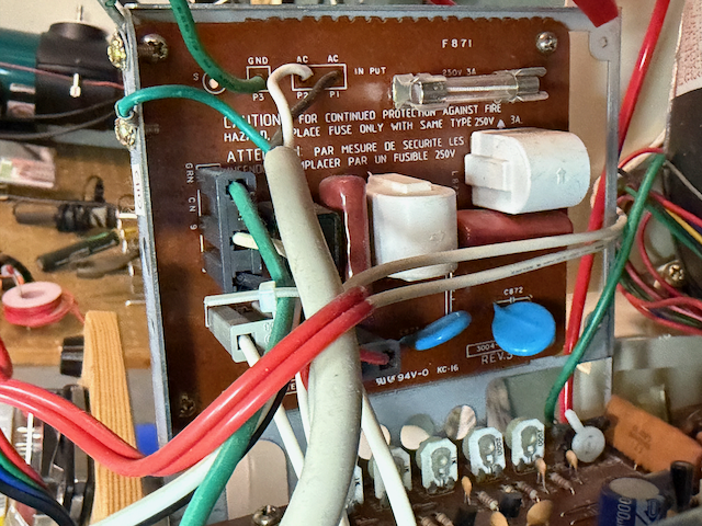
 AC Power filter board AC Power filter board | 649.6 KB |
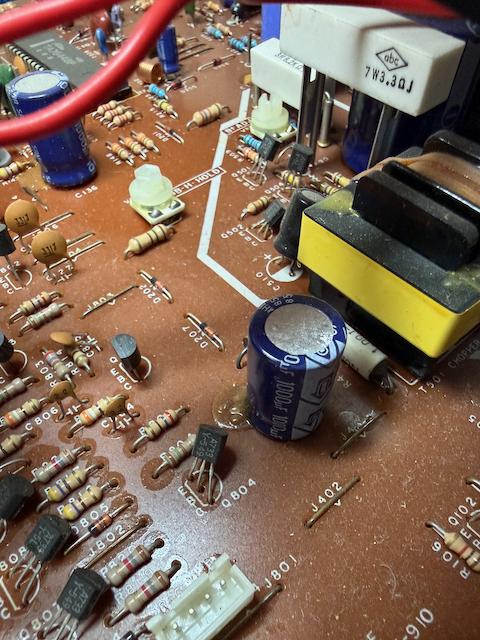
| Low-voltage RGB leaky C410 | 659.91 KB |
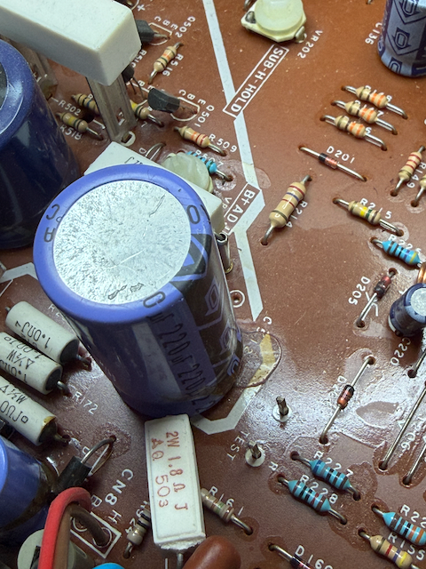
| B+ Filter Leaking C512 | 626.06 KB |
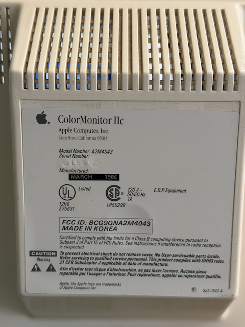
| Monitor Case A2M4043 | 481.04 KB |
| Main board | 695.3 KB |
(crossposted on vcfed.org forums)
Hey all,
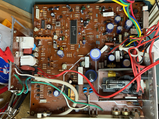
I've decided, for good or ill, to recap a newly acquired A2m4043 color monitor IIc. It is exhibiting a narrow raster image and, upon teardown and inspection, has at least a few leaky caps in the B+ filter area (among other areas). No rifa caps to be found. I've attached a few pics of the board for posterity. My plan is to replace the big leaky caps in the LIVE / B+ filter area plus whatever else I think I can handle. Mostly posting this here as a way to report progress and ask for advice. I haven't found much info on these monitors (schematics etc) yet... Here's what I do know:
Some specs:Model: A2M4043 Apple ColorMonitor IIcChassis: TWE-3003-705-910Tube Builder: ToshibaIC101: TA7644BPConfirmed leaking caps:C506, C512, C140, C410, C136
What you're calling "leaking" may not be what you think it is. In assmblies like these, the heavier components (large capacitors, inductors, and transformers) have glue applied to prevent vibrations.
Usually, the suspect caps for leaking are the small electrolytics like C220.
That's very interesing - I did not know this. Not surprisingly then, I don't know how to differentiate glue from electrolytic goo.
Can you see the attached photo referencing C512? Does that offer any clues?
The glue is rubbery and is not affected by water, where leaked electrolyte is soluble in water, alcohol, or acetone and feels "tacky".
Amine additives in the electrolyte typically have an odor described as "fishy".
Glue sometimes can cause problems, especially if it turns a brown color. That signals a chemical decomposition that turns the glue conductive and corrosive, in which case it is best to remove it. If I recall correctly, it does help to use acetone, although it is more to help soften it rather than truly dissolve that stuff.
The "C512" picture may show both a glue dot and leaked electrolyte. The leaking appears to have spread out as far as R215 in one direction, and as far as J206 in another. It should wash off in warm water, but you're right to plan on replacing C512 first if that was the leak's source.
Thanks for the reply. I'm fighting my inexperience here and am grateful for the help. The "sheen" I'm seeing seems to be coming from C512, but also exists around many of the other components and thru-holes. Possibly just a ton of flux?
Also, C506 may be bulging at the top - but again, that might be totally normal. I'll attempt to attach some more pics.
shiny_stuff_1.png
shiny_stuff_2png.png
In second image you can see C506's covered by slightly rounded top. Everything else seems fine (aside from the narrow raster, that is!). I'm at a bit of a loss for what to try / look at next.
Can you post a picture of the screen with what you describe as a narrow raster? I’ve owned a number of these over the years and the raster always looks more narrow than maybe you feel like it should be. I’m curious if that’s what we’re talking about or if there’s a real issue at play.
Boy that would have been a good idea to do first wouldn't it? <kicks self>. I feel like there's maybe an inch of border on the left and right? seemed excessive. But yeah I really should have confirmed here first. <another kick>
If it still works once I put it back together I'll post a pic :)
The Apple IIgs suffers from the same affliction and if the RGB monitor or TV does not have the ability to control the width, there is nothing you can do about it:
SCARTSetup.JPG
Since the residue is around basically all of the holes, it does look like flux got oversprayed (the flux sprayer on the wave solder machine may have been running "hot and thin" that day).
The plastic isolator on C520 is distorted, but I've seen that happen just with heat cycles over time. Hard to tell if that cap has gone high ESR just by looking at it.
The horizontal image size will depend on how much overscan the display is set up for. Apple II video (in text mode) outputs bytes at ~1 MHz, or once every µs. There are 40 bytes per line, which makes a horizontal line ~40 µs long; but the NTSC horizontal active area is 53 µs! Using such a small part of the available active area is one way to ensure that the full image is visible on consumer TVs, which had a significant and variable overscan. The overscan was the reason for the "safe area" rules that limit the size of anything needing to be visible (like text or captions) to 80% of the active area.
Computer displays needed to be set up differently, with underscan instead of overscan, so the results in terms of image size can be far from ideal.
Thanks for the insight. Perhaps my monitor is okay after all. Beautiful IIgs!
Wow - that is very useful information - thank you! There IS a width coil (L204 I think) with a hex lug. I am very tempted to turn it and see what happens. But I'm also increasingly aware that my monitor is probably fine.
You can definitely adjust the picture width from there. A lot of CRT monitors from the 80s have it. My Taxan Composite/RGB monitor even came with the long plastic hex tool to adjust it:
Back.jpg
That is not 100% accurate, because it would make the horizontal resolution in 40-column text mode 40 x 8 = 320 pixels, when in reality it's only 280 pixels. Instead you could say: the Apple II video outputs 7 bits at ~1 MHz, or once every microsecond.
Or to be even more precise, in 40-column text mode the Apple II video outputs one bit every 2 cycles of the 14.318181 MHz clock. In high-resolution color mode or double hi-res monochrome mode it outputs one bit every single 14.318181 MHz clock cycle, giving us an effective horizontal monochrome resolution of 560 pixels.
That makes the horizontal line: (1 / 14318181) x 560 = 39.1 µs long.
I didn't say anything about pixels, because the way they are output is more complicated and that doesn't have any effect on the active area. The graphics formats have been discussed here ad nauseam, but the active time per line barely at all.
Each byte in text mode displays a (7 × 8) character cell. In fact, the text, low-res graphics, and high-res graphics are all always running, and the mode just selects which one feeds the display output.
My first draft discussed pixels in HR mode: but how many pixels are there? The echt Apple II Reference Manual gives 280, but that isn't perfectly accurate, since there are 560 positions in a line that could be on or off.
But the active time per line is directly determined by the number of pixels that need to be displayed. For example if the font width was not 7 pixels, but 8 like in the Commodore 64 or the original IBM CGA adapter, then the horizontal resolution in 40-column text mode would have been 320 instead of 280 and the active time per line would have been 44.7 µs instead of 39.1 µs. That in tern would have resulted smaller margins, which is what this discussion was all about.
Given all this information, here is my new plan:
Please let me know if anything in that list seems particularly thick-headed! This thread has been super helpful - thanks again.
One thing to keep in mind is that the width coil usually affects multiple voltage rails in the circuit.
I would try to support the front band of the CRT; never let any object get close to the neck. The tube is not designed to be supported by its neck.
An update, of a sort...
After much wrestling with the bezel and the tube, I managed to reconnect everything and re-assemble the monitor (there has got to be an easier way than how I did it...). With the DMM connected to what I inferred the B+ rail to be, (hot leg of R502, low leg of R509), I connected AC via the dim bulb tester and fired it up.
It worked! HV crackle, bulb light up brightly then dimmed, B+ voltage rose to 75 or so.
Then I powered down for the full mains test, discharged the anode...and blew my DMM fuse...? (Did I mention I'm new at this?). New fuses are on the way.
I tried the full mains test anyway with a DVD player hooked up playing a test pattern. All looked pretty good except for two things:
1. Image off center (biased to the left, a good two inches of black right-hand margin)
2. No color! argh Occasionally on startup there is a rolling flash of color (red / blue). I'm hoping I just reversed the CN5 white-button switch (the switch seems to do nothing now, no effect when pressing it).
Thinking about it some more - I'm possibly measuring B+ against the wrong ground reference. Should I be using an isolated chassis ground or the 'live' ground reference (what the - pin of the big filter caps are connected to)
If anyone has suggestions on how best to proceed, I'd appreciate it greatly.
Thanks,
Nick
Was the lead of your DMM plugged into an "amps" or "milliamps" jack? That could explain the fuse blowing.
B+ voltage is usually connected to the horizontal yoke. The ground to use for a reference is the emitter of the H.O.T.
Well I was wrong (and right!) again.
I was making an attempt to measure voltage, so i was plugged into the voltage jack. No fuse protection there. Bye bye DMM :(
I'll take out the board again (sigh) and see if I can confirm Q202 (in my schematic) as the B+ return. On my schematic (hand drawn by Someone On The Internet but so far has proven accurate) Q202 ties into the flyback and +50v
q202.png
The protection circuit (which uses no fuse) in a DMM should take no damage from 1000 V; the equivalent circuit for the voltage input is a 1 megaohm resistor in series with a transistor. What you can't measure with a DMM (unless a HV probe is used) are kilovolt electrodes like the Focus and EHT outputs of the flyback transformer.
Okay interesting - maybe a sharp current spike then? Anode discharge-> DMM connected to B+ went blank -> turned back on, just reads 0.00 now, no continuity, no ohm readings, no dc voltage on new batteries etc. Weird.
On the color issue, here's a picture (and a video if I can upload it) showing what I mean.
IMG_0679.JPEG
The lovely rainbow effect oscillates rapidly for 10 seconds or so and then snaps to black and white until a cold startup.
Video link
Thanks,
Nick
Was this a result from your intervention, or was this problem present before? Take a look at the crystal oscillator and the circuitry around it. Its function is to generate and lock to the short color burst signal that comes in the beginning of each line and it's clearly failing to do that. The crystal itself can break internally if subjected to a shock, since it is a very thin piece of quartz crystal.
If this is a result of recapping, it could also have been caused by replacing with an incorrect-valued or defective capacitor.
I noticed from your photos that next to the crystal oscillator there is a trim capacitor. It is there in order to finetune the generated frequency to be as close as possible to NTSC's color subcarrier frequency of 3.579545 MHz. Try adjusting it to see if you can achieve a frequency lock:
TrimCap.png
CVT - thanks! I will give that a try.
The color sync was working before I went on this adventure. No major shocks or bumps though, and I ended up not replacing any parts, caps included. I sure hope I didn't break anything. I did turn the B+ pot a bit chasing another issue (dead DMM). Once I get a new DMM I'll revalidate the B+ rail voltage.
Side note: It's very difficult to access many of these pots while the CRT is "put together". I can slide the main board out from under the neck a little bit, but not much. Are these adjustments meant to be be done "live" (taking necessary precautions, one-hand rule, etc) or done cold with everything off and discharged? I'd rather not be reaching under the energized neck. I have decent non-conductive alignment tools.
Thanks,
Nick
The adjustments need feedback from watching the image, so the shock hazard is unfortunately part of the bargain with CRT servicing. One idea is wearing nitrile rubber gloves: they won't hold off thousands of volts from EHT, but the bigger hazard is the +400 V in the power supply and the B+ and they can save you there.
A plastic adjustment tool is a requirement, not only because of the shock hazard, but because the circuit could malfunction if a ferromagnetic tool is used to adjust a variable coil. Some of the earlier large monitors have clips to store a tool on the outer shield in case of "on site" adjustments.
To adjust the trim capacitor, because of the miniature size you are pretty much forced to use a regular small Philips screwdriver with a plastic handle instead. There are special tools for it, but they are pretty expensive and due to the much higher torque they will get damaged if they are of low quality. The only thing to keep in mind is that the capacity changes when then you touch it with the metal tip of the screwdriver, so you will have to adjust it to where you want it after you lift the screwdriver. It just takes a few seconds longer to adjust, but there is no danger of damaging the circuit.
Should I be picking up an isolation transformer before I do this? I'm pretty sure the whole chassis isn't hot, but I'm thinking measuring B+ will be running mains-referenced +170 thru my meter...not sure how concerned I shoud be about that if I'm just reading values.
There is no need for an isolation transformer and there is no need to measure anything, since the monitor is working other than the fact that it cannot lock to the color subcarrier frequency. Simply make sure not to touch anything conductive with your hand while the monitor is working.
Agreed that an isolation transformer is not called for. They do not always provide more safety; far from it. Besides, the isolation would be defeated when connecting any video source, unless it was itself isolated.
If you do have to resort to a metal screwdriver to turn the preset cap, you can wrap all but the tip with electrical tape to prevent contact with any nearby object.
Thanks again, this has been incredibly helpful. Quick progress update and then two specific questions.
The trouble I'm having with the trimmer cap: I tried adjusting the subcarrier trimmer (the small one in the yellow holder near the crystal), but I'm basically flying blind:
My two questions:
Due to how the pot is situated in the trim capacitor, I wasn't able to mark a starting spot. I kept track of how many turns in what direction etc and hopefully got back to where I started.
Thanks so much — I feel like I'm one adjustment away from a fully working monitor and just need to get at it properly.
Nick
There is no color-killer circuit in the monitor to disable. The reason it goes to black and white is probably because it's programed to give up after it cannot lock after a certain amount of time and to simply assume a monochrome signal.
The trim capacitor rotates forever, but its full range is only 180 degrees. If you think of it as a clock, if the minimum capacity is at 6 o'clock, then the maximum is at 12 o'clock. You can spin it forever - it doesn't have any hard stops. You never need to rotate it more than 1 turn to know for certain that you have gone through its full range, since its full range is only half a turn.
If you want to start properly diagnosing this, you might want to get an oscilloscope. Even through the full schematics is not available, there is enough in the TA7644BP datasheet to get you started: TA7644BP.pdf
Just a quick update on this.
No luck with turning the pot yet (Turned quite slowly, 1/2 turn in 20-30 seconds). Measured 13.6V on pin 3 of the TA7644BP - higher than the 12V on the datasheet, but within spec. Currently scratching my head and saving up for an oscilloscope...probably sometime in August.
Nick
For a beginner I would recommend a hand-held battery-powered in the $100 range. You can get a decent 2-channel 50 MHz oscilloscope. Just watch the YouTube reviews to figure out which one gives you the best bang for the buck. If you get a mains-powered grounded oscilloscope, you can easily burn both the oscilloscope and the monitor. With an isolated battery-powered one you can measure signals between any two points without having to worry about shorting something.
Thanks for the insight there - I will consider a hand-held scope.
Once I get it - what would you recommend I look for? My hazy plan is to rule out a bad crystal, then try to see if the color lock trim pot (C126) is doing what it should. Not sure where to go from there.
Nick
AI says:
In a color TV, APC (Automatic Phase Control) detects and synchronizes the color burst signal with the local 3.58 MHz (or 4.43 MHz) oscillator. This ensures that the TV's color demodulators receive the correct phase references to accurately reproduce colors.
...and in this particular case it happens to be 100% correct.
Now clearly the APC detector, (which I have marked in red below) is not working properly. At this stage I can come up with at least 6 possible reasons:
1. The color-burst signal coming in the video input on pin 6 is dampened or muffled. You can check this with an oscilloscope - it should be a clean sine wave in the beginning of each line.
2. The inverting amplifier marked in blue inside the chip is not amplifying. This is also something you can check with an oscilloscope on pin 7. The signal should be stronger and inverted compared to the signal on pin 6.
3. There is something wrong with the color-killer filter marked 1 in green.
4. There is something wrong with the APC filter marked 2 in green.
5. There is something wrong with the oscillator circuit marked 3 in green. You can check this with an oscilloscope on the oscillator drive pin, which is pin 16. You should see a nice sine wave with a frequency of ~3.58 MHz.
6. The chip itself is damaged, in which case I would suggest you order a new one from eBay: https://www.ebay.com/itm/126472847316 along with a socket.
Now before even your oscilloscope arrives, there is something you need to do, since the schematic on the last page of the datasheet is of very bad quality and not necessarily what you have. It's more of Toshiba's suggestion how you should design a TV using their chip. This is why you need to look at the PCB and manually redraw all the stuff inside the green rectangles:
Schematics.png
Looks like your A2M4043 is identical (same chassis, and board photos look familiar) as my A2M2056, which I just spent meany hours pouring over to reverse engineer a schematic.
Latest PDF/SVG here:
https://github.com/fredsa/apple-color-monitor-iie-a2m2056
I'm still trying to improve the layout. Feedback appreciated.
Here's a thumbnail of the schematic:
A2M2056-schematic-thumbnail-2026-06-29.png
It is great that the chassis is identical to the A2M2056 and that someone has taken the time to put it all in KiCad, thus eliminating the need to trace anything from the PCB.
I also suggest watching this video from Adrian's Digital Basement ][ for safety's sake, since this is a partially hot and partially grounded chassis: https://www.youtube.com/watch?v=Ve5gsO4u7pc
Careful not to touch that heatsink! Keep in mind that a chassis that is both hot and grounded is even more dangerous, because touching the hot part with one hand while touching the grounded part with the other can kill you.
This schematic plus David Gribble's hand-drawn effort have been extremely useful. Thank you!
I will watch the safety video - I've learned a ton the past couple of months but this can only help. I'm staying away from the LIVE (as marked on the board) area for my recent problem with the APC / color sync lock. I'm in a bit of a holding pattern right now while I wait for some tools and a block of time to work on it.
It's a beautiful CRT, newly retro-brighted as well. Hope I can save it. I'm sure I'll have more questions in the coming weeks (hopefully not months)
Thanks again,
Nick
I finally have something new here. I managed to get a hold of a basic hand-held o-scope (Zoyi) and have spent the last few days figuring out to use it.
Pin references below are for the Toshiba chip labeled IC101 in Fred's schematic above (thanks Fred!)
Have not yet checked the inverted signal on pin 7.
As always I welcome opinions on what I should try next!
Thanks,
Nick
Why not start with that? Did you get a one-channel or two-channel oscilloscope? If you got the latter, it would be nice to see pin 6 and pin 7 side-by-side.
Okay, did some more probing and got a clean signal on pin 6 and 7.
Ch1 is pin 6, Ch2 is pin 7.
PIC_6176_pin_6_and_7.jpg
I think that's right? Pin 7 is amplified and inverted. Looks like I messed up the vertical scale so the amplification is magnified 2x.
Here's the color burst on pin 6:
PIC_3947_back_porch.png
Looks "normal" to me, but I'm very new at this.
Nick
Pin 15 is an input (take a look at the datasheet, there is no arrow coming out of it), so there is no reason why it would change when the IC gives up. At this point my advice would be to get another chip from eBay + a socket and change it. That will most likely fix the problem.
Btw, do you happen to have a monochrome CRT monitor or a modern HDTV with a component input? If you do, please make the same video as you posted in response #24 above. These two types of monitors have a horizontal resolution that is high enough to see the actual "color" as monochrome vertical lines. If you have the latter, you need to connect the composite output of the Apple II to the Y-Component input:
Sony Bravia Y-Component.JPG
I don't have either, but I do have a composite -> HDMI adapter that I've tested with my IIc and IIe successfully. I'm guessing that won't answer any question you have though...
Before I attempt to pull the chip out I'm considering soldering on some flying leads to the more relevant IC pins. I've had a lot of trouble attaching my scope probe hook to the wide/flat IC pins. This leads to unreliable results because it's easy to short pins together. Sometimes I can probe elsewhere in the circuit in a mechanically easier spot (resistor leg etc), sometimes not.
Back to head-scratching....
If you have tested with a composite to HDMI adapter, it already confirms that there is nothing wrong on the Apple II side.You can also double- or even tripple-socket it, which not only gives you the freedom to solder wires for probing, but also to disconnect individual pins.
Some examples of tripple-socketing from this forum: click! and click!