Apple I Tape Interface

15 posts / 0 new
Last post
Offline
Last seen: 3 years 7 months ago
Joined: Mar 9 2005 - 03:00
Posts: 79
Apple I Tape Interface

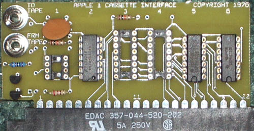
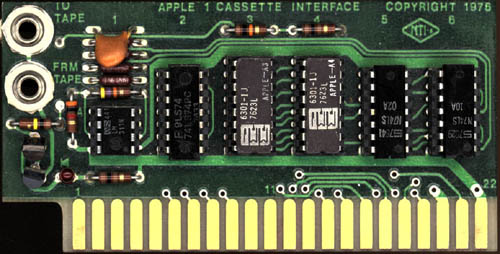
I'm reasearching the Apple I tape interface. The function of the LS02, LS10, and LM311 is obvious. Are the 6301-IJ, 7623L chips ROM, or are they 6301 microcontrollers? I know the wonder book contains notes on the tape interface...somewhere, so I will begin the 230 page search.

Anytime now a bunch of really cool Apple I documets will get added to the archive. Smile

Offline
Last seen: 3 years 7 months ago
Joined: Mar 9 2005 - 03:00
Posts: 79
http://coinop.org/kb_dl.aspx/

http://coinop.org/kb_dl.aspx/kb/gametech/rom-ram_reference.html

the 6301-1 is a 256x4 memory. I don't suppose Apple ever released schematics or assembler listings for the casette card?

From the pictures I'm going to map what I can, and try to fill in the blanks based on what "should" be there.

It was easy to rule out a 6301 microcontroller, considering it has 40 pins. Wink

Offline
Last seen: 3 years 7 months ago
Joined: Mar 9 2005 - 03:00
Posts: 79
Questions:

Questions:

There is a schematic of a casette interface on page 64 of the
Wonderbook. The schematic appears to be preliminary to the Apple I.

I need someone with an Apple I card to identify the 4 resistors under
the capacitor. I would also like an ID on the two transistors (they
are boxed in white). Any markings will help. Please also look at the
trace that wraps around the transistors from the red diode. Does it
connect to the collector of both transistors? (I'm assuming at least
the bottom is NPN due to the connections)

Anyone with any documentation on the casette interface would help.
The Wonderbook is not literally very clear in this area. I have all
the schematic drawn but the address decoding logic. I'm almost done
prooving it out and will post it sunday night. My goal is to have
gerber files ready sunday evening to get two of these casette boards
made. Verification of resistor values is not critical for this, but knowing the transistor situation is. A picture from a lower left angle of the board would help me.

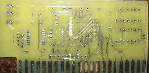
NOTE: the traces seen over the chips are what is on the bottom of the board.

Any questions or comments? Its 3:30AM in Alaska. The east coast is waking up... Wink

Thanks for the help. Wink

IMAGE(http://www.stockly.com/images1/050313-Apple1CardCopy1.jpg)

Offline
Last seen: 9 months 14 hours ago
Joined: Dec 20 2003 - 10:38
Posts: 249
Reduce the size of that picture

Otherwise it will take dialup people forever to see it. Instead of image use thumb. Here is the schematic for the apple 1 cassette:

Apple 1 cassette interface schematics

Hope this helps,

Vince

Offline
Last seen: 3 years 7 months ago
Joined: Mar 9 2005 - 03:00
Posts: 79
Yes, that helps. I wish I'd

Yes, that helps. I wish I'd found that earlier! Wink Amazingly my schematic matches that one exactly except for the component values. Its fairly easy to rule out which traces pass under the chips based on previous traces.

However, in the note section next to the chip select on pin 21 it says to jumper R to C. pin 21 on the interface is chip select T according to the apple manual. Did I miss something? I can't edit the post to change the picture size.

To a degree that is reasonable I'm making the card clone look exactly like the one pictured. Smile

Offline
Last seen: 9 months 14 hours ago
Joined: Dec 20 2003 - 10:38
Posts: 249
Yes, R (pin 21) to C (74154 p

Yes, R (expansion pin 21) to C (74154 pin 14) jumper would be the address decoder for $C000. In order for the apple 1 to use the cassette interface the address decoder The apple 1 gave hard-wired memory decoding options. Always fun to try and reverse engineer a board but good job. If you look at the schematic of the apple 1 at IC B9 the 74154 /CSC is the C Woz is referring to. Looking closer at the 74154 you can see every output is for 4K blocks for the ability to actually address upto the full 64K of memory range. The 44pin card only had enough room for 3 memory selects so Woz left the choice up to the user but for the cassette, R needs to be jumpered to C so that the cassette interface code is at C100 (because A4 is selected on the card). Sorry, I'm going on, hope this helps too.

Vince

Offline
Last seen: 15 years 4 months ago
Joined: Mar 15 2004 - 09:47
Posts: 17
ROM disasm

The 256 bytes of cassette interface ROM contain console input and evaluation of parameters (about 130 bytes, the code is very clear and some routines are similar to the monitor ROM, or same only using differet registers (X instead of Y or so), ECHO subroutine from monitor ROM is used) and tape I/O itself (cca 100 bytes) - code is not so clear here, with many nested loops and entry points to subroutines.
As soon as I will found it, I will post the tape interface source code here (if nobody will be faster than me).

Offline
Last seen: 3 years 7 months ago
Joined: Mar 9 2005 - 03:00
Posts: 79
Go ahead and post your findin

Go ahead and post your findings. Knowing the locations in memory of the cassette hardware would help figuring out those loops. I bet they are for encoding and decoding the data. The Apple 1 cassette adaptor is similar to the Disk II and IWM, it requires very specific processor timing to read the data.

All right, I made my images much smaller this time. Smile

I blured the top of this board. Tell me what it does. The surface mount chip on this boad has 4k of ram. Smile
IMAGE(http://www.stockly.com/images1/031905-Apple1MysteryCard.jpg)

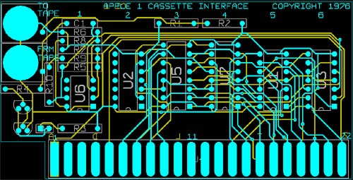
Here is the board I drew up last weekend. I placed the components within +-.050 of the origional board. The traces, an autorouter took care of that. I am not TOO crazy. Wink
IMAGE(http://www.stockly.com/images1/031905-Apple1Cassette.jpg)

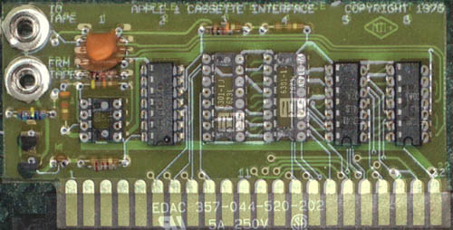
Here is the real one in case you forgot.
IMAGE(http://www.stockly.com/images1/031905-Apple1RealCassette.jpg)

And the real one with mine on top of it. (to see how close the parts are) Even the labeling is "close". Wink I didn't spend more than 10 seconds on this, so its not very well alligned.
IMAGE(http://www.stockly.com/images1/031905-Apple1CassettesMorph.jpg)

My last attempt to slow down the internet:
IMAGE(http://www.stockly.com/images1/031905-Apple1CassetteBoardLayout.jpg)

Have fun. I'll upload the gerber files once it's been tested. I don't want to be responsible for people wasing their money on an untested board. Wink

Offline
Last seen: 13 years 7 months ago
Joined: Apr 10 2005 - 10:02
Posts: 5
First I would like to say HI!

First I would like to say HI! I'm new around here. I will soon be
building a Replica 1.

Has anyone produced a working cassette interface replica?

iceandfire's picture
Offline
Last seen: 7 years 11 months ago
Joined: Dec 20 2003 - 10:38
Posts: 67
Welcome!

Welcome to the forum, rasterscan, and to the world of the Apple-I. Up to now, no one has announced that they have a working cassette interface for the Replica-I. It seemed easy for Woz in the 70's but the duplication of his efforts seems almost imposible. Here's hoping all those out there with the skills needed will have lots of luck with this projsct soon.

Larry

Offline
Last seen: 15 years 4 months ago
Joined: Mar 15 2004 - 09:47
Posts: 17
Go ahead and post your findings.

>> Go ahead and post your findings. Knowing the locations in memory of the cassette hardware would help figuring out those loops.
>> I bet they are for encoding and decoding the data.

You are right, of course.
Here is it (use non-proportional font):
</p> <p>Apple 1 Tape ROM disassembly</p> <p>written by WOZ, 1976<br /> disasm by dex, 2005</p> <p>FROM:STL<br /> STH<br /> TO: XAML<br /> XAMH</p> <p>C100 RESET_T LDA #AA '*'<br /> C102 JSR FFEF ECHO<br /> C105 LDA #8D 'CR'<br /> C107 JSR FFEF ECHO<br /> C10A LDY #FF<br /> C10C NOCR INY<br /> C10D NEXTCHAR_T LDA D011 KBD_CR<br /> C110 BPL C10D NEXTCHAR_T<br /> C112 LDA D010 KBD<br /> C115 STA 200,Y IN<br /> C118 JSR FFEF ECHO<br /> C11B CMP #9B 'ESC'<br /> C11D BEQ C100 RESET_T<br /> C11F CMP #88 'CR'<br /> C121 BNE C10C NOCR<br /> C123 LDX #FF<br /> C125 NXBLOCK LDA #00<br /> C127 STA 24 XAML<br /> C129 STA 25 XAMH<br /> C12B STA 26 STL<br /> C12D STA 27 STH<br /> C12F NEXTHEX_T INX<br /> C130 NEXTITEM_T LDA 200,X IN<br /> C133 CMP #D7 'R'<br /> C135 BEQ C18D READ<br /> C137 CMP #D7 'W'<br /> C139 BEQ C170 WRITE<br /> C13B CMP #AE '.'<br /> C12D BEQ C166 STOREHEX<br /> C137 CMP #8D 'CR'<br /> C141 BEQ C163 ESCAPE_T<br /> C143 CMP #A0<br /> C145 BEQ C12F NEXTHEX_T<br /> C147 HEX EOR #B0<br /> C149 CMP #0A<br /> C14B BCC C153 DIG_T<br /> C14D ADC #88<br /> C14F CMP #FA<br /> C151 BCC C100 RESET_T<br /> C153 DIG_T ASL A<br /> C154 ASL A<br /> C155 ASL A<br /> C156 ASL A<br /> C157 LDY #04<br /> C159 HEXSHIFT_T ASL A<br /> C15A ROL 24 XAML<br /> C15C ROL 25 XAMH<br /> C15E DEY<br /> C15F BNE C159 HEXSHIFT_T<br /> C161 BEQ C12F NEXTHEX_T<br /> ------------------------------------<br /> C163 ESCAPE_T JMP FF1A ESCAPE<br /> ---------------------------------<br /> C166 STOREHEX LDA 24 XAML<br /> C168 STA 26 STL<br /> C16A LDA 25 XAMH<br /> C16C STA 27 STH<br /> C16E BCS C12F NEXTHEX_T<br /> ------------------------------------</p> <p>C170 WRITE LDA #40<br /> C172 WLOOP1 JSR C1CC ENTRY1<br /> C175 DEY<br /> C176 LDX #00<br /> C178 LDA (26),X STL<br /> C17A LDX #10<br /> C17C WLOOP2 ASL A<br /> C17D JSR C1DB WAIT1<br /> C180 BNE C17C WLOOP2<br /> C182 JSR C1F1 TEST_END<br /> C185 LDY #1E<br /> C187 BCC C175 WLOOP1<br /> C189 LOOP1 LDX 28<br /> C18B BCS C125 NXBLOCK</p> <p>C18D READ JSR C1BC ENTRY2<br /> C190 LDA #16<br /> C192 JSR C1CC ENTRY1<br /> C195 JSR C1BC ENTRY2<br /> C198 RLOOP1 LDY #1F<br /> C19A JSR C1BF READPORT<br /> C19D BCS C198 RLOOP1<br /> C19F JSR C1BF READPORT<br /> C1A2 LDY #3A<br /> C1A4 RLOOP2 LDX #08<br /> C1A6 RLOOP3 PHA<br /> C1A7 JSR C1BC ENTRY2<br /> C1AA PLA<br /> C1AB ROL A<br /> C1AC LDY #39<br /> C1AE DEX<br /> C1AF BNE C1A6 RLOOP3<br /> C1B1 STA (26),X STL<br /> C1B3 JSR C1F1 TEST_END<br /> C1B6 LDY #35<br /> C1B8 BCC C1A4 RLOOP2<br /> C1BA BCS C189 LOOP1<br /> --------------------------------<br /> C1BC ENTRY2 JSR C1BF READPORT<br /> C1BF READPORT DEY<br /> C1C0 LDA CO81 PORT<br /> C1C3 CMP 29 H<br /> C1C5 BEQ C1BF READPORT<br /> C1C7 STA 29 H<br /> C1C9 CPY #80<br /> C1CB RTS<br /> --------------------<br /> C1CC ENTRY1 STX 28 L<br /> C1CE LOOP3 LDY #42<br /> C1D0 JSR C1E0 WAIT3<br /> C1D3 BNE C1CE LOOP3<br /> C1D5 ADC #FE<br /> C1D7 BCS C1CE LOOP3<br /> C1D9 LDY #1F<br /> C1DB WAIT1 JSR C1E0 WAIT3<br /> C1DE LDY #2C<br /> C1E0 WAIT2 DEY<br /> C1E1 BNE C1E0 WAIT2<br /> C1E3 BCC C1EA ENTRY3<br /> C1E5 LDY #2F<br /> C1E7 WAIT3 DEY<br /> C1E8 BNE C1E7 WAIT3<br /> C1EA ENTRY3 LDY C000,X PORT_C0XX<br /> C1ED LDY #29<br /> C1EF DEX<br /> C1F0 RTS<br /> --------------------<br /> C1F1 TEST_END LDA 26<br /> C1F3 CMP 24<br /> C1F5 LDA 27<br /> C1F7 SBC 25<br /> C1F9 INC 26<br /> C1FB BNE C1FF RTS.1<br /> C1FD INC 27<br /> C1FF RTS.1 RTS<br /> ====================<br />

Offline
Last seen: 2 years 9 months ago
Joined: May 10 2005 - 23:06
Posts: 11
Auto router (not always your friend)

Logjam,

Your Cassette board looks great, but I do want to draw your attention to one small detail that may cause a great deal of trouble on your board. The power distribution traces, are way too small. Notice on the original board how wide the Vcc and Gnd traces are. Also note how direct they are routed.

Auto routers can be made to work for the signal traces, but power traces usually need special attention. Please consider revising your design in this area.

Sincerely,
Rich

Offline
Last seen: 6 years 9 months ago
Joined: May 11 2005 - 23:40
Posts: 5
Re: Go ahead and post your findin

Go ahead and post your findings. Knowing the locations in memory of the cassette hardware would help figuring out those loops. I bet they are for encoding and decoding the data. The Apple 1 cassette adaptor is similar to the Disk II and IWM, it requires very specific processor timing to read the data.

I don't want to steal belegost1's thunder, but since I had already written an insanely detailed annotation of the Apple-1 cassette ROM code while working on my emulation of the cassette interface for MESS, I figure that others should be allowed to benefit from it.

<br /> ;;; Notes on interface hardware:<br /> ;;;<br /> ;;; Selected by $Cxxx.<br /> ;;;<br /> ;;; ROMs enabled by $C1xx and $C0xx.<br /> ;;;<br /> ;;; Output flip-flop to tapeout toggled by each access to $C0xx.<br /> ;;;<br /> ;;; Tapein input not enabled for accesses to $C00x-$C07x. Accesses to<br /> ;;; these addresses always access the corresponding ROM address<br /> ;;; ($0x-$7x).<br /> ;;;<br /> ;;; Accesses to $C08x-$C0Fx enable the tapein input.<br /> ;;;<br /> ;;; When tapein input is low, the low bit of the address passes<br /> ;;; through normally, so the location accessed will be the<br /> ;;; corresponding ROM address ($8x-$Fx).<br /> ;;;<br /> ;;; When tapein input is high, the low bit of the address is ignored<br /> ;;; and is always treated as 0. In this case an access of $C08x-$C0Fx<br /> ;;; will hit ROM address $8y-$Fy, where y is (x &amp; ~1).<br /> ;;;<br /> ;;; Of course, only read accesses will show any effect; write accesses<br /> ;;; are no-ops except for their effect on the tapeout output flip-flop.<br /> ;;;<br /> ;;; Tapein input comes from a National Semiconductor LM311 voltage<br /> ;;; comparator, which simply turns the audio input analog waveform into<br /> ;;; a digital square wave, based on its zero crossings.</p> <p>;;; Disassembly of the Apple I cassette interface ROM.</p> <p>;;; Variables:<br /> ;;;<br /> ;;; $200-$2FF: command buffer<br /> ;;; $24: L -- low byte of address in command;<br /> ;;; A2L -- low byte of 2nd address in range.<br /> ;;; $25: H -- high byte of address in command;<br /> ;;; A2H -- high byte of 2nd address in range.<br /> ;;; $26: A1L -- low byte of 1st address in range.<br /> ;;; $27: A1H -- high byte of 1st address in range.<br /> ;;; $28: saved X register<br /> ;;; $29: LASTIN -- last tape line level read.</p> <p>;;; Prepare to read a command from the keyboard.</p> <p>C100: A9 AA lda #$AA ; Prompt for command: "*\r"<br /> C102: 20 EF FF jsr $FFEF<br /> C105: A9 8D lda #$8D<br /> C107: 20 EF FF jsr $FFEF<br /> C10A: A0 FF ldy #$FF ; Y is command buffer index, will start at 0.</p> <p> ;; Command entry loop:<br /> C10C: C8 iny<br /> C10D: AD 11 D0 lda $D011 ; Loop until key ready.<br /> C110: 10 FB bpl $C10D<br /> C112: AD 10 D0 lda $D010 ; Load key character.<br /> C115: 99 00 02 sta $0200,y ; Add character to buffer.<br /> C118: 20 EF FF jsr $FFEF ; Display it.<br /> C11B: C9 9B cmp #$9B ; : cancel and prompt for new command.<br /> C11D: F0 E1 beq $C100<br /> C11F: C9 8D cmp #$8D ; : enter command<br /> C121: D0 E9 bne $C10C ; Otherwise continue reading command.<br /> ;; (Note there is no check for command buffer overflow;<br /> ;; entering more than 256 bytes will overwrite the start of<br /> ;; the buffer.)</p> <p>;;; Prepare to parse and execute a command.</p> <p>C123: A2 FF ldx #$FF ; X is command buffer index, will start at 0.</p> <p>C125: A9 00 lda #$00 ; Clear variables L/A2L, H/A2H, A1L, A1H.<br /> C127: 85 24 sta $24<br /> C129: 85 25 sta $25<br /> C12B: 85 26 sta $26<br /> C12D: 85 27 sta $27</p> <p> ;; Command parsing loop:<br /> C12F: E8 inx<br /> C130: BD 00 02 lda $0200,x<br /> C133: C9 D2 cmp #$D2 ; "R"<br /> C135: F0 56 beq $C18D<br /> C137: C9 D7 cmp #$D7 ; "W"<br /> C139: F0 35 beq $C170<br /> C13B: C9 AE cmp #$AE ; "."<br /> C13D: F0 27 beq $C166<br /> C13F: C9 8D cmp #$8D ; : marks end of command;<br /> C141: F0 20 beq $C163 ; return to Monitor.<br /> C143: C9 A0 cmp #$A0 ; " ": spaces are simply skipped.<br /> C145: F0 E8 beq $C12F<br /> C147: 49 B0 eor #$B0 ; Map digit characters to values 0-9.<br /> C149: C9 0A cmp #$0A ; Is character a digit?<br /> C14B: 90 06 bcc $C153 ; If so, skip hex mapping.<br /> C14D: 69 88 adc #$88 ; Map hex letters A-F to values $FA-$FF.<br /> C14F: C9 FA cmp #$FA ; Was character a hex letter?<br /> C151: 90 AD bcc $C100 ; If not, bad command--get a new one.<br /> C153: 0A asl a ; Shift hex digit value to A's high nybble.<br /> C154: 0A asl a<br /> C155: 0A asl a<br /> C156: 0A asl a<br /> ;; Loop to shift digit from A's high nybble into H:L variables.<br /> C157: A0 04 ldy #$04 ; 4 iterations.<br /> C159: 0A asl a ; Shift A's high bit to carry.<br /> C15A: 26 24 rol $24 ; Rotate carry into L's low bit, L's high bit into carry.<br /> C15C: 26 25 rol $25 ; Rotate carry into H's low bit.<br /> C15E: 88 dey<br /> C15F: D0 F8 bne $C159 ; End of loop.<br /> C161: F0 CC beq $C12F ; Digit finished; parse next command character.</p> <p>C163: 4C 1A FF jmp $FF1A ; Command finished; jump to Monitor.</p> <p> ;; A "." marks a 2-address range.<br /> C166: A5 24 lda $24 ; Save L, H in A1L, A1H.<br /> C168: 85 26 sta $26<br /> C16A: A5 25 lda $25<br /> C16C: 85 27 sta $27<br /> C16E: B0 BF bcs $C12F ; Parse next command char.<br /> ;; (An equal CMP sets carry, so this branch is always taken.)</p> <p>;;; End of command parsing code.</p> <p>;;; Tape I/O code follows.</p> <p>;;; Tape Write<br /> ;;; ----------<br /> ;;;<br /> ;;; We write a 10-second record-header to the tape, followed by the<br /> ;;; data.<br /> ;;;<br /> ;;; Tape bits are formed by formed by two alternating half-bit pulses.<br /> ;;; A "half-bit" is a pulse (half-cycle) of the proper length for the<br /> ;;; bit value to write.<br /> ;;;<br /> ;;; The 10-second record-header has 8192 + X header bits, plus 1 sync<br /> ;;; bit. Each header bit is composed of two 593-clock half-bits. The<br /> ;;; sync bit has a 181-clock first half and a 239-clock second half.<br /> ;;;<br /> ;;; (At an effective processor clock speed (with RAM refresh waits) of<br /> ;;; 980 KHz, the header bits would form a 826 Hz square wave.)<br /> ;;;<br /> ;;; Data is written one byte at a time, from low to high addresses.<br /> ;;; Each byte is written most-significant bit first.<br /> ;;;<br /> ;;; Each data bit is composed of two half-bits, 239 clocks each for a<br /> ;;; "0" bit, 474 clocks each for a "1" bit.<br /> ;;;<br /> ;;; (With the same clock speed as above, we get 2050 Hz for the "0"<br /> ;;; bits and 1034 Hz for the "1" bits.)<br /> ;;;<br /> ;;; (The first half-bit after the end of each byte is 227 clocks for a<br /> ;;; "0" half-bit, 462 clocks for a "1" half-bit. This goes up by 4<br /> ;;; clocks at the end of a 256-byte page. It seems Wozniak was just a<br /> ;;; little off in his path equalization, though this may have been<br /> ;;; deliberate.)<br /> ;;;<br /> ;;; When we start, carry is set, due to the last equal compare. Also,<br /> ;;; X is set to the index of the last command char examined. This<br /> ;;; makes very little difference in practice, since this index is<br /> ;;; almost always small.</p> <p>;;; Write the 10-second record-header.<br /> C170: A9 40 lda #$40 ; Call TAPE_HDR() with A = 64.<br /> C172: 20 CC C1 jsr $C1CC ; (TAPE_HDR() saves X register in $28.)<br /> ;;; Write the data.<br /> ;; (Y = 40 on first call to WRBIT.)<br /> C175: 88 dey<br /> C176: A2 00 ldx #$00<br /> C178: A1 26 lda ($26,x) ; Load the next data byte from A1.<br /> ;; Shift each data bit into carry flag and write it to tape.<br /> C17A: A2 10 ldx #$10 ; X = 16 (# of half-bits per byte)<br /> C17C: 0A asl a<br /> C17D: 20 DB C1 jsr $C1DB ; Call WRBIT() for this bit.<br /> C180: D0 FA bne $C17C<br /> C182: 20 F1 C1 jsr $C1F1 ; Byte done; call CMP_INC() to update A1.<br /> C185: A0 1E ldy #$1E ; Y = 29 on next call to WRBIT().<br /> C187: 90 EC bcc $C175 ; Repeat until address range is finished.</p> <p>;;; Used for both Tape Write and Tape Read:<br /> C189: A6 28 ldx $28 ; Restore X register saved by TAPE_HDR().<br /> C18B: B0 98 bcs $C125 ; Parse next command, resetting A1 &amp; A2.</p> <p>;;; Tape Read<br /> ;;; ---------<br /> ;;;<br /> ;;; We can handle a record header of varying length, but it must be<br /> ;;; longer than ~3.5 seconds.<br /> ;;;<br /> ;;; The record header half-bits should be substantially longer than<br /> ;;; 402 clocks, and the sync bit's first half-bit should be<br /> ;;; substantially shorter than 378 clocks; the length of the second<br /> ;;; half-bit doesn't matter.<br /> ;;;<br /> ;;; (For an effective processor clock speed (with RAM refresh waits) of<br /> ;;; 980 KHz, the header-bit square wave should be under 1218 Hz.)<br /> ;;;<br /> ;;; Data is read one byte at a time, from low to high addresses. Each<br /> ;;; byte is read most-significant bit first. (Of course, this is the<br /> ;;; same order as the data was written.)<br /> ;;;<br /> ;;; Each data bit (two half-bits) should be substantially shorter than<br /> ;;; 700 clocks to be recognized as a "0" and substantially longer than<br /> ;;; 731 clocks to be recognized as a "1".<br /> ;;;<br /> ;;; (For the same clock speed as above, the "0" bits should be over<br /> ;;; 1400 Hz and the "1" bits should be under 1340 Hz.)<br /> ;;;<br /> ;;; When we start, Y may contain old data, but it will have no effect.</p> <p>;;; Read the record-header.<br /> ;; Lock on to the tapein waveform, initializing LASTIN.<br /> ;; (If no tapein waveform ever shows up, this call will hang.)<br /> C18D: 20 BC C1 jsr $C1BC ; Call RDBIT(). (Y value doesn't matter.)<br /> ;; Wait for 22*128 header bit periods, each of 1186 clocks.<br /> ;; Thus this is a 3.4-second delay, assuming a 980 KHz effective<br /> ;; clock rate.<br /> ;; The idea is to get far enough into the header to avoid glitches<br /> ;; from the tape leader.<br /> C190: A9 16 lda #$16 ; Call TAPE_HDR() with A = 22.<br /> C192: 20 CC C1 jsr $C1CC ; (TAPE_HDR() saves X register in $28.)<br /> ;; Lock onto the tape waveform again.<br /> C195: 20 BC C1 jsr $C1BC ; Call RDBIT() (Y value doesn't matter.)<br /> ;; Start reading record-header bits, looking for the start of the<br /> ;; sync bit.<br /> ;;<br /> ;; Any half-bit shorter than 378 clocks will always qualify,<br /> ;; and a half bit of up to 402 clocks might qualify if the<br /> ;; timing happens to be right.<br /> ;;<br /> ;; The standard header half-bits of 593 clocks should<br /> ;; definitely fail, and the standard sync bit's first half-bit<br /> ;; of 181 clocks should definitely qualify.<br /> C198: A0 1F ldy #$1F ; Call RDHALFBIT() with Y = 31.<br /> C19A: 20 BF C1 jsr $C1BF<br /> C19D: B0 F9 bcs $C198 ; Repeat until we find an early tapein edge.<br /> ;; An early edge signals that we found the sync bit. Read the<br /> ;; second half of it.<br /> C19F: 20 BF C1 jsr $C1BF ; Call RDHALFBIT().<br /> ;;; Read the data.<br /> C1A2: A0 3A ldy #$3A ; Y = 58 on next call to RDBIT().<br /> ;; Read each data bit from tape into carry flag and rotate it into<br /> ;; data byte.<br /> ;;<br /> ;; Any bit shorter than 700 clocks will always read as "0",<br /> ;; and any bit longer than 731 clocks will always read as "1".<br /> ;; Bits which fall in the range of 700-731 clocks could be<br /> ;; read as either "0" or "1" depending on their timing. This<br /> ;; is the "indeterminate zone" which valid bits must avoid.<br /> ;;<br /> ;; For the standard lengths of 478 clocks for "0" and 948<br /> ;; clocks for "1", there should be no problems.<br /> C1A4: A2 08 ldx #$08<br /> C1A6: 48 pha ; Save A, since RDBIT() will clobber it.<br /> C1A7: 20 BC C1 jsr $C1BC ; Call RDBIT() for this bit.<br /> C1AA: 68 pla ; Restore A.<br /> C1AB: 2A rol a ; Rotate bit from carry into A.<br /> C1AC: A0 39 ldy #$39 ; Y = 57 on next call to RDBIT().<br /> C1AE: CA dex<br /> C1AF: D0 F5 bne $C1A6<br /> C1B1: 81 26 sta ($26,x) ; Data byte complete--store it at A1.<br /> C1B3: 20 F1 C1 jsr $C1F1 ; Call CMP_INC() to update A1.<br /> C1B6: A0 35 ldy #$35 ; Y = 53 on next call to RDBIT().<br /> C1B8: 90 EA bcc $C1A4 ; Repeat until address range is finished.<br /> C1BA: B0 CD bcs $C189 ; Restore X reg. and parse next command.</p> <p>;;; RDBIT()<br /> ;;; Read a bit (a full cycle) from the cassette interface.<br /> ;;;<br /> ;;; This simply perfoms two successive calls to RDHALFBIT(). So it finishes<br /> ;;; the pulse begun by the last tapein edge, reads another complete pulse,<br /> ;;; and then reads the start of a third pulse.<br /> ;;;<br /> ;;; Time elapsed: 12*(Yin - Yout) + 10 clocks.<br /> ;;; 12*(Yin - Yout) - 6 clocks to 2nd tapein edge; subtract<br /> ;;; up to 12 clocks for late-detection error.<br /> ;;; 16 clocks after 2nd edge; add up to 12 clocks for<br /> ;;; late-detection error<br /> ;;;<br /> ;;; On return, Y has been reduced by the time elapsed to the 2nd tapein<br /> ;;; edge (in counts), and may be negative (&gt;= $80).<br /> ;;; Carry flag is set if Y is negative.<br /> ;;; Zero and neg flags reflect the result of the Y compare with $80.<br /> ;;;<br /> ;;; If the Y parameter is set to the expected time (in counts) until<br /> ;;; the 2nd tapein edge, the Y result will be the difference between<br /> ;;; the expected and actual time to the edge (positive for an early<br /> ;;; edge, negative for a late edge). The carry flag will be clear for<br /> ;;; an early or on-time edge and set for a late edge.<br /> ;;;<br /> ;;; If Y is set to the *average* time until the 2nd edge, based on<br /> ;;; a 50-50 chance of the data bit being 0 or 1, carry will be clear<br /> ;;; for a 0 bit (shorter than average) and set for a 1 bit (longer<br /> ;;; than average). Thus the carry flag will contain the bit value.<br /> ;;;<br /> ;;; (It is possible in principle for Y to wrap around, but this would<br /> ;;; only happen if the 2nd edge was 256 or more counts after the call,<br /> ;;; or 3072 clocks, which is longer than any waveform used by the<br /> ;;; cassette interface.)</p> <p>C1BC: 20 BF C1 jsr $C1BF ; Call RDHALFBIT().<br /> ;; fall through to RDHALFBIT().</p> <p>;;; RDHALFBIT()<br /> ;;; Read a half-bit from the cassette interface.<br /> ;;;<br /> ;;; This examines the tapein line until it sees an edge. So it<br /> ;;; doesn't read a complete half-bit pulse; it only sees the end of<br /> ;;; the pulse that started in the last RDHALFBIT() call and the start<br /> ;;; of the next pulse.<br /> ;;;<br /> ;;; Time elapsed: 12*(Yin - Yout) + 10 clocks.<br /> ;;; 12*(Yin - Yout) - 6 clocks to tapein edge; subtract<br /> ;;; up to 12 clocks for late-detection error.<br /> ;;; 16 clocks after 2nd edge; add up to 12 clocks for<br /> ;;; late-detection error<br /> ;;;<br /> ;;; On return, Y has been reduced by the time elapsed to the tapein<br /> ;;; edge (in counts), and may be negative (&gt;= $80).<br /> ;;; Carry flag is set if Y is negative.<br /> ;;; Zero and neg flags reflect the result of the Y compare with $80.<br /> ;;;<br /> ;;; If the Y parameter is set to the expected time (in counts) until<br /> ;;; the next tapein edge, the Y result will be the difference between<br /> ;;; the expected and actual time to the edge (positive for an early<br /> ;;; edge, negative for a late edge). The carry flag will be clear for<br /> ;;; an early or on-time edge and set for a late edge.</p> <p>C1BF: 88 dey ; Decrement Y.<br /> ;; Tapein line is enabled by accesses to address region $C08x-$C0Fx.<br /> ;; When the line is low, the value read is that at the corresponding<br /> ;; ROM address $C18x-$C1Fx. When the line is high, the value read<br /> ;; is that at ROM address $C18y-$C1Fy, where y is (x &amp; ~1). So in<br /> ;; this case, we read ROM address $C181 (value $FA) when tapein is<br /> ;; low and ROM address $C180 (value $D0) when tapein is high. This<br /> ;; effectively indicates the tapein line level.<br /> C1C0: AD 81 C0 lda $C081 ; Read tapein line level.<br /> C1C3: C5 29 cmp $29 ; Repeat until the line level is different<br /> C1C5: F0 F8 beq $C1BF ; from LASTIN.<br /> C1C7: 85 29 sta $29 ; Save current tapein level in LASTIN.<br /> C1C9: C0 80 cpy #$80 ; Set carry if Y wrapped around.<br /> C1CB: 60 rts </p> <p>;;; TAPE_HDR()<br /> ;;; Write tape record header bits and sync bit.<br /> ;;; (Also used as a convenient delay when reading the record-header.)<br /> ;;;<br /> ;;; There will be A*128 + X/2 header bits.<br /> ;;;<br /> ;;; Each header bit is composed of two long "1" half-bits of 593 clocks each;<br /> ;;; every 256th half-bit is 597 clocks.<br /> ;;;<br /> ;;; The sync bit is a short "0" half-bit of 181 clocks, followed by a normal<br /> ;;; 239-clock "0" half-bit, with 15 clocks afterward.<br /> ;;;<br /> ;;; This is always called with carry set.<br /> ;;; A contains the number of 128-bit header-bit blocks.<br /> ;;; X is the number of extra header half-bits; its value is saved in $28.<br /> ;;; On return, A is 255, X is 254, Y is 41;<br /> ;;; carry flag is clear, zero flag clear, neg flag set.</p> <p>C1CC: 86 28 stx $28 ; Save X register.<br /> ;; Do header bits: (A*256 + X) calls to WRHALFBIT() with Y = 66.<br /> C1CE: A0 42 ldy #$42 ; Call WRHALFBIT() with Y = 66.<br /> C1D0: 20 E0 C1 jsr $C1E0<br /> C1D3: D0 F9 bne $C1CE<br /> C1D5: 69 FE adc #$FE ; Decrement A.<br /> C1D7: B0 F5 bcs $C1CE ; Repeat until A wraps around to $FF.<br /> ;; Now do the sync bit; carry is clear.<br /> C1D9: A0 1E ldy #$1E ; Call WRBIT() with Y = 30.<br /> ;; fall through to WRBIT().</p> <p>;;; WRBIT()<br /> ;;; Write a bit (a full cycle) to the cassette interface.<br /> ;;;<br /> ;;; This simply perfoms two successive calls to WRHALFBIT(). Therefore<br /> ;;; it finishes the pulse begun by the last tapeout edge, creates another<br /> ;;; complete pulse, and then begins a third pulse.<br /> ;;;<br /> ;;; Time elapsed:<br /> ;;; "0" bit: 5*Y + 262 clocks.<br /> ;;; 5*Y + 8 clocks to 1st tapeout edge,<br /> ;;; 239 clocks to 2nd tapeout edge, 15 clocks after 2nd edge.<br /> ;;; "1" bit: 5*Y + 732 clocks.<br /> ;;; 5*Y + 243 clocks to 1st tapeout edge,<br /> ;;; 474 clocks to 2nd tapeout edge, 15 clocks after 2nd edge.<br /> ;;;<br /> ;;; Parameters and results are as for WRHALFBIT(), except that X is<br /> ;;; decremented twice.<br /> C1DB: 20 E0 C1 jsr $C1E0 ; Call WRHALFBIT().<br /> C1DE: A0 2C ldy #$2C ; Repeat WRHALFBIT() with Y = 44.<br /> ;; fall through to WRHALFBIT().</p> <p>;;; WRHALFBIT()<br /> ;;; Write a half-bit to the cassette interface.<br /> ;;;<br /> ;;; What this actually does is to wait for a specified time before toggling<br /> ;;; the tapeout line, generating a rising or falling edge. So this doesn't<br /> ;;; write a complete half-bit pulse; rather, it finishes the pulse begun by<br /> ;;; the last WRHALFBIT() call and starts a new pulse.<br /> ;;;<br /> ;;; Time elapsed:<br /> ;;; "0" half-bit: 5*Y + 17 clocks.<br /> ;;; 5*Y + 2 clocks to tapeout edge, 15 clocks after edge.<br /> ;;; "1" half-bit: 5*Y + 252 clocks.<br /> ;;; 5*Y + 237 clocks to tapeout edge, 15 clocks after edge.<br /> ;;;<br /> ;;; Carry flag = value of half-bit to write (clear for "0", set for "1")<br /> ;;; Y = number of counts to tapeout toggle (depends on previous code path)<br /> ;;; X = half-bit counter (decremented for each call)<br /> ;;; A and carry flag are unchanged; Y is set to 41; X is decremented.<br /> ;;; Zero and neg flags reflect the result of the X decrement.</p> <p> ;; "0" half-bit: delay of (5*Y - 1 + 3) clocks before tapeout toggle.<br /> C1E0: 88 dey ; Spin Y times (delay (5*Y - 1) clocks).<br /> C1E1: D0 FD bne $C1E0<br /> C1E3: 90 05 bcc $C1EA ; Skip to tapeout toggle if carry clear.<br /> ;; "1" half-bit: extra delay of 235 clocks before tapeout toggle.<br /> C1E5: A0 2F ldy #$2F ; Spin 47 times (delay (2 + 5*47 - 1) clocks).<br /> C1E7: 88 dey<br /> C1E8: D0 FD bne $C1E7<br /> ;; Tapeout line is toggled by each access to address region $C0xx;<br /> ;; any such access toggles the output flip-flop to the tapeout line.<br /> ;; The direction of access makes no difference. X has no effect on<br /> ;; this; it's just used here for timing purposes. (Although unused,<br /> ;; the value loaded will be the ROM byte at $C100+X.)<br /> ;; Remaining delay: 5 + 2 + 2 + 6 = 15 clocks.<br /> C1EA: BC 00 C0 ldy $C000,x ; Toggle tapeout.<br /> C1ED: A0 29 ldy #$29 ; Y = 41<br /> C1EF: CA dex<br /> C1F0: 60 rts </p> <p>;;; CMP_INC()<br /> ;;; Compare A1 to A2, increment A1.<br /> ;;; Carry is set if A1 &gt;= A2 before the increment, otherwise clear.<br /> ;;;<br /> ;;; Time elapsed: 26 clocks (30 clocks if increment of A1H required).<br /> ;;;<br /> ;;; (This takes advantage of the fact that CMP and SBC on the 6502<br /> ;;; use and set the carry flag in the opposite sense from most<br /> ;;; processors: carry = 1 for no borrow, carry = 0 for borrow.)</p> <p>C1F1: A5 26 lda $26 ; A1L<br /> C1F3: C5 24 cmp $24 ; A1L - A2L<br /> ;; If A1L &gt;= A2L, carry = 1; if A1L &lt; A2L, carry = 0.<br /> C1F5: A5 27 lda $27 ; A1H<br /> C1F7: E5 25 sbc $25 ; A1H - A2H<br /> ;; If A1L &gt;= A2L and A1H &gt;= A2H, carry = 1<br /> ;; If A1L &gt;= A2L and A1H &lt; A2H, carry = 0<br /> ;; If A1L &lt; A2L and A1H &gt; A2H, carry = 1<br /> ;; If A1L &lt; A2L and A1H &lt;= A2H, carry = 0<br /> ;; Now carry flag == (A1 &gt;= A2).<br /> ;; Increment A1 and return.<br /> C1F9: E6 26 inc $26 ; Increment A1L.<br /> C1FB: D0 02 bne $C1FF<br /> C1FD: E6 27 inc $27 ; Increment A1H.<br /> C1FF: 60 rts<br />

Offline
Last seen: 6 years 9 months ago
Joined: May 11 2005 - 23:40
Posts: 5
Apologies for broken code formatting...

Sorry about how the above code came out; something seems to be wrong with how this board's software handles the "code" tag. And what's with the substitution of "l-e-g-o" with "EvilBlockCompany"?

iceandfire's picture
Offline
Last seen: 7 years 11 months ago
Joined: Dec 20 2003 - 10:38
Posts: 67
Assembly of Cassette Interface Software

This has to be the most complete (and best) commented disassembly of the cassette code for the Apple-I that I have ever seen. Great Job!

Log in or register to post comments