| Attachment | Size |
|---|---|
| 3.8 MB | |
| 3.4 MB | |
| 2.53 MB | |
| 2.76 MB | |
| 3.08 MB | |
| 1.57 MB |
Hello everyone. I've got an Apple 2+ that I found in my childhood attic that I am trying to bring back to life, but am not sure how to proceed. I've bolded the current sticking points I am experiencing in getting it to operate.
The computer came with the following expansion cards:
Language Card - 670-X006, Expands memory to 64K, must be in Slot 0.
Videx VideoTerm - 80 column display card, must be in Slot 3 It also has a small add-on board that slots into the 9334, but utilizing the chip in the add-on board, I still do not receive any video from this card.
Apple 650-X104 Disk ][ Drive Card - Enables floppy controller communication, must be in Slot 6
Z-80 SoftCard - Microsoft SoftCard, enables device to run CP/M, Slot 4
Asynchronous Serial Interface - Model 7710, enables serial communication over port (Not sure which Slot this goes in.
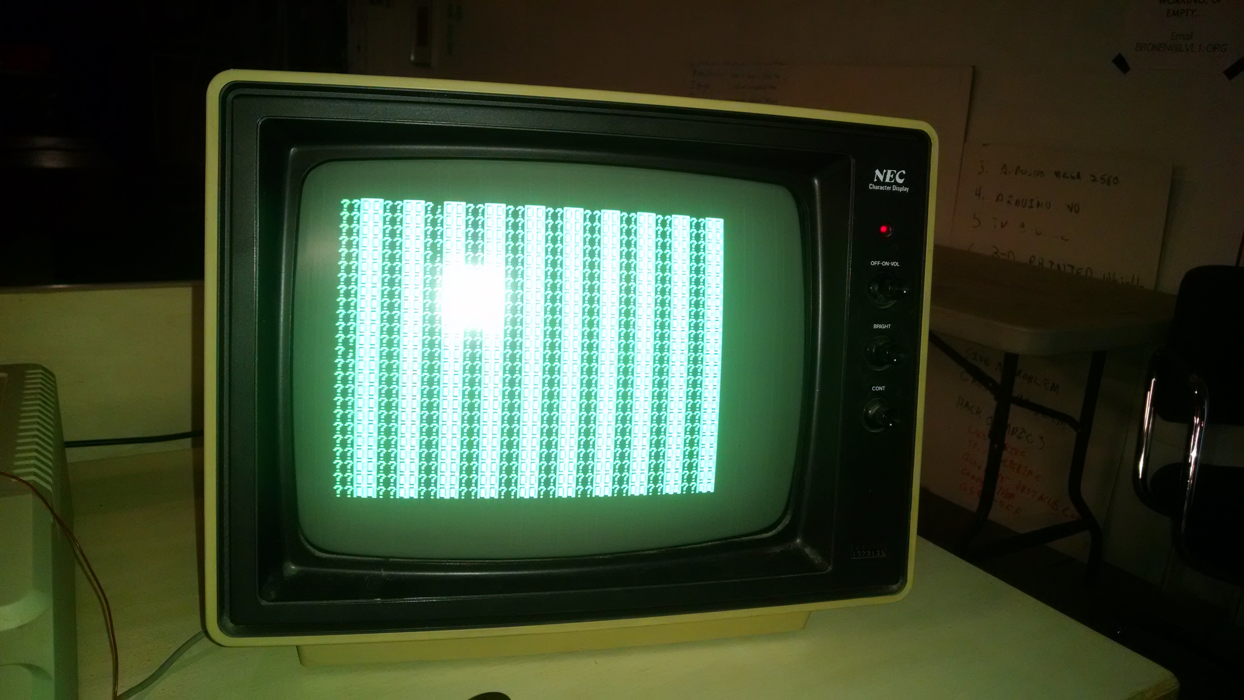
Upon initial startup, the unit would only display an array of alternating ??DD lines, filling the 24x40 display.
See the Initial Startups image.
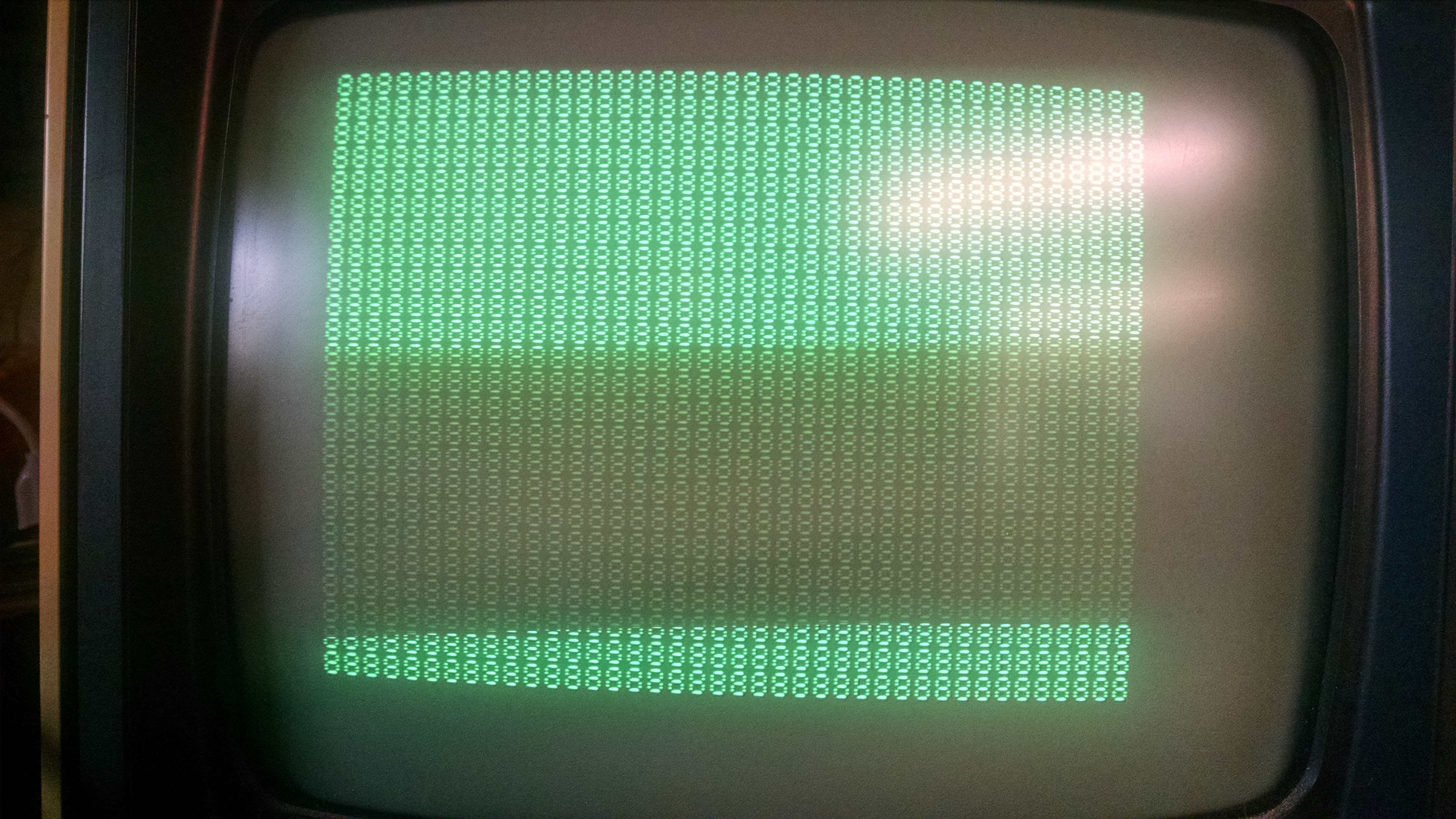
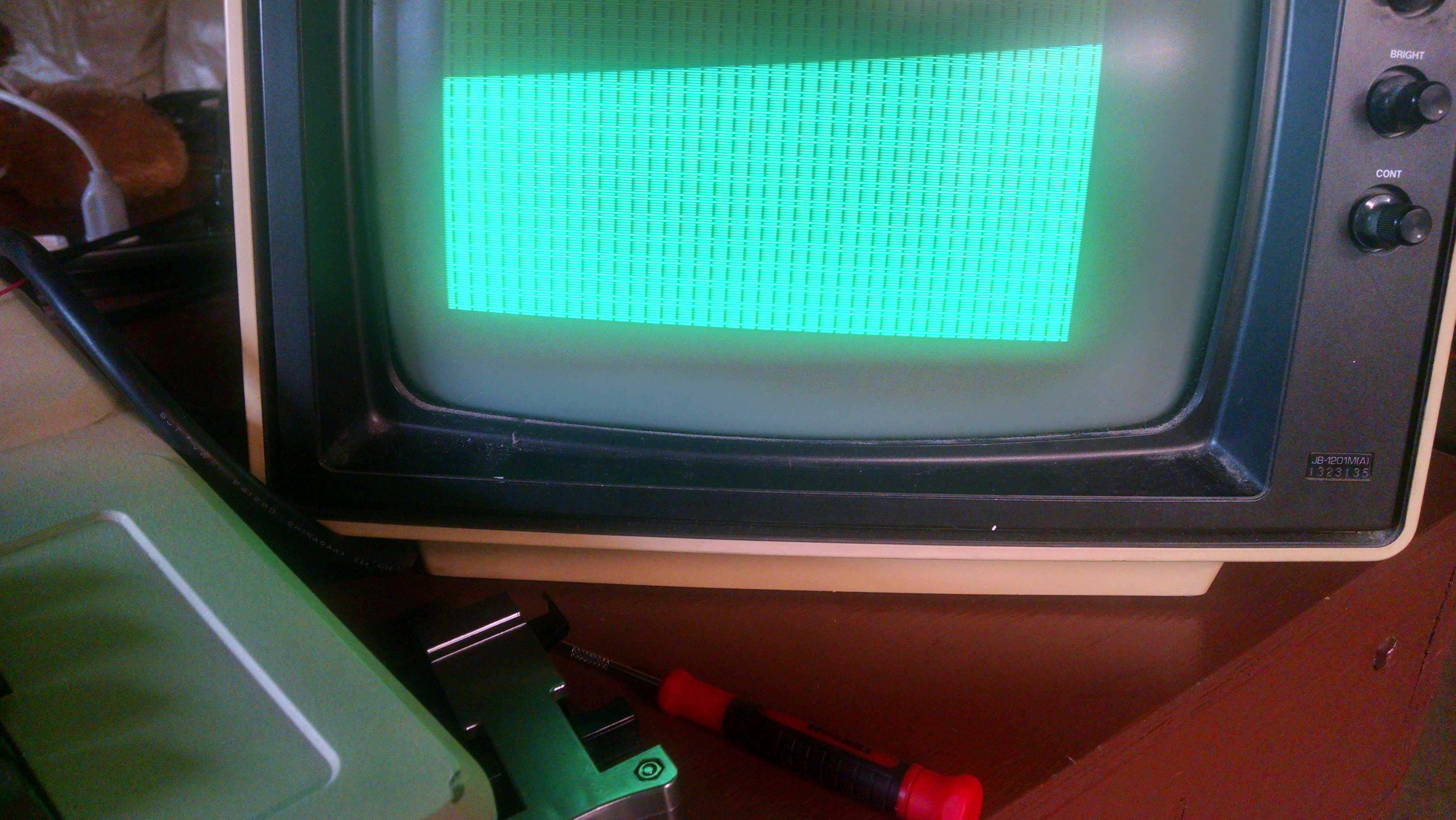
After I removed each ROM chip and cleaned the legs with 50% isopropyl alcohol and a lens cloth, and removed/remounted each of the 24 RAM chips, I'm making it a little farther. I see that initial screen for a second, followed by a filled screen of blocks (the empty spaces look something like upside down exclamation marks), followed by a screen full of 8's. This is where the computer freezes now. Resetting the computer with the reset key sometimes gets it to the filled screen of blocks, sometimes 8's, sometimes it cycles between the two. Lately it's instead been filling the screen with 0's.
See Block Screen image.
See Screen of 8s image.
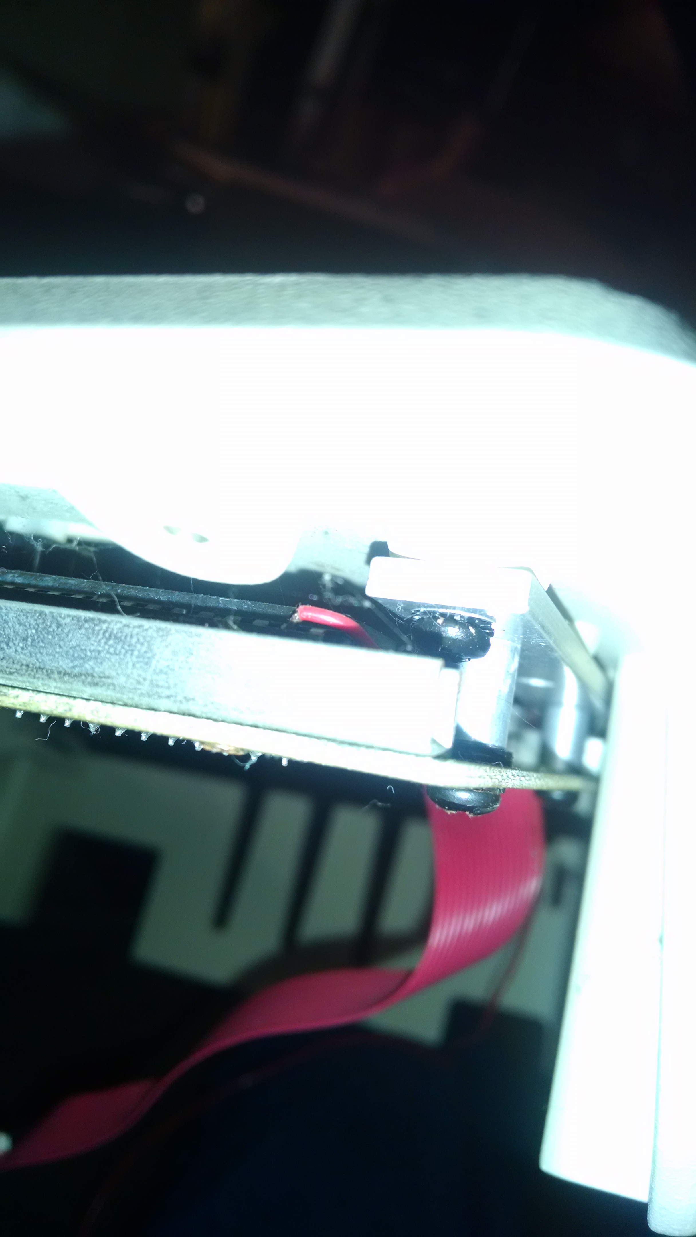
I have been unable to identify a single red wire that seems to come out of the same location on the unit as the keyboard wires. It is not attached to anything and is instead free-floating, so I route it out of the machine to avoid shorting it against anything.
I've tried running the system with just a single bank of 8, as I read in other forums. I've also tried running the unit in various other configurations (with and without the language card). Most of my present attempts involve utilizing the language card but keeping all other cards disconnected. What are my next steps?
If you are truly interested in diagnostics, I am an electronics hardware engineer, I have LOVE for my vintage apples but all of them have been working fine from purchase. So if you don't get the help the help you need here and want to get more hands on pm me, I will give you my number and we can work real time on this.
Samm
welcome to the community JousterL,
see the behaviour is only one part of the diagnostic task....
inspect ( view ) the mainboard is the other part of the task....
within the last 5 months there have been several several such tasks performed here.
at least 2 pictures from top of the mainboard and 2 from bottom of the mainboard
would be required. see previos threads for examples by entering Apple II and diagnostic
in the search field at the top right side to get a list from previos tasks.
place here links to that pictures from your mainboard like eplained above
( about 2500 x 4000 pixels with sharp focus to enable zoom in at the picture while viewing )
- the bottem ( solderside ) is required because some mods in former days have been performed
at solderside. This also enables to check for dirt and loose wires, cut traces
or alternate wiring and condition of the soldering joints below of the mainboard.
waiting for the feedback
sincerely
speedyG
It seems the supply to be OK but i´d recommend to check the voltages anyhow with
multimeter.
I've attached new pictures to the top post:
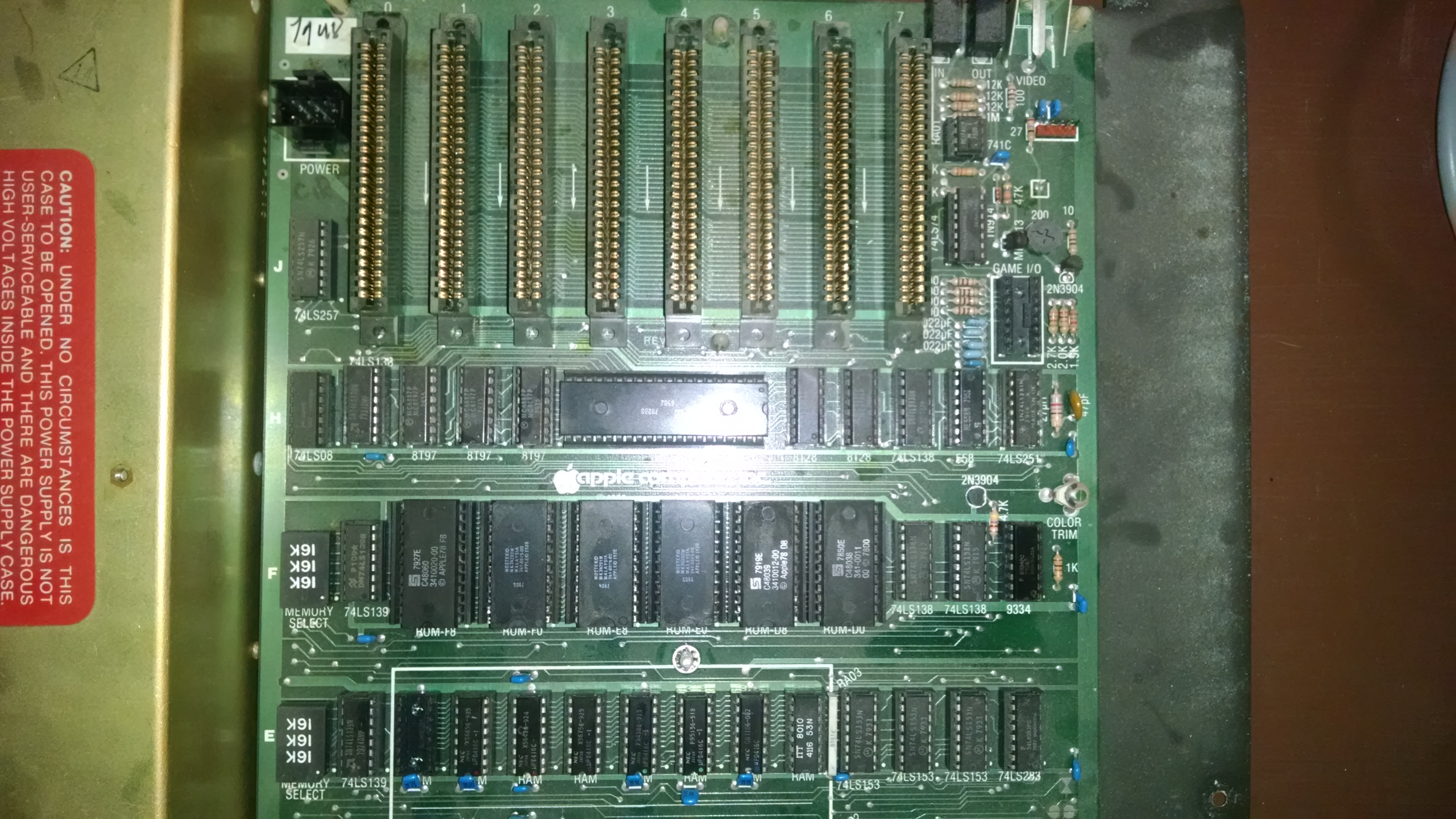
-Top.jpg is the top part of the mainboard, with the slots.
-Bottom.jpg is the bottom part of the mainboard, with the RAM.
-Single Wire.jpg is the red wire I mentioned before. It seems to be soldered to one of the pins on a chip on the keyboard. I would need to unscrew the keyboard from the pressed plastic body to determine which pin it was.
Hello JousterL,
sorry for the delay caused by other tasks....
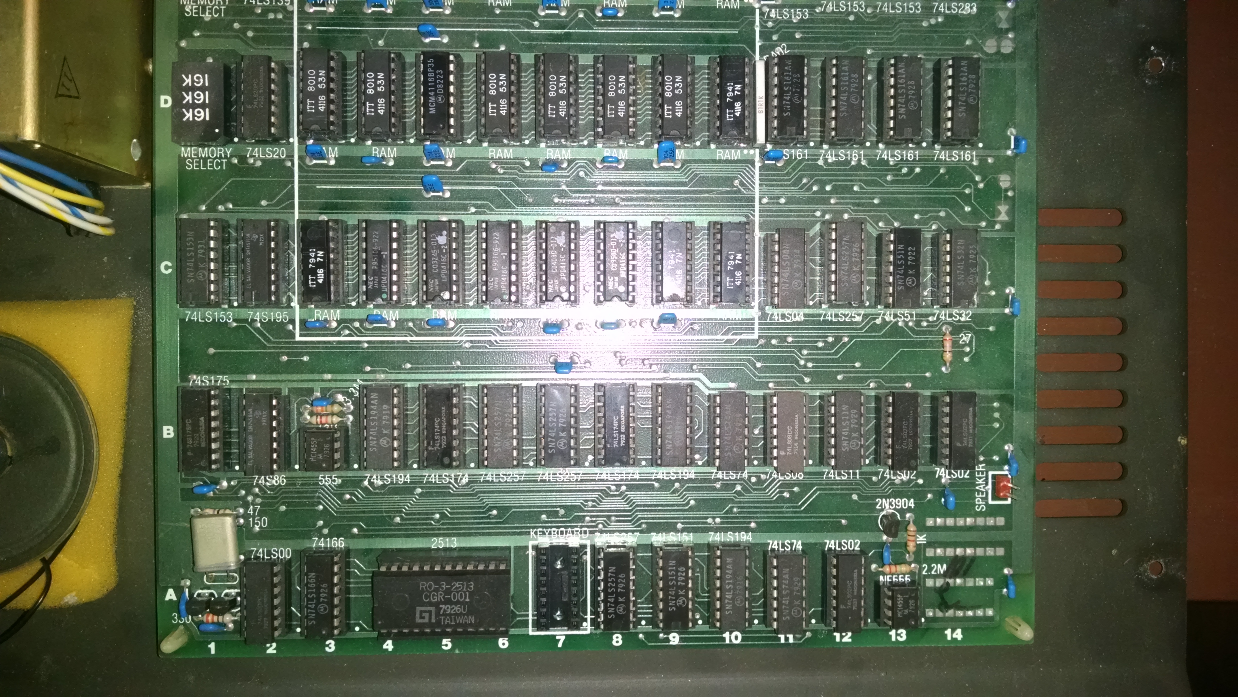
according to the picture below here is a list of recommendations and
remarks:
A: The F8 Rom seems to have heavy oxydation at the pins.
It´s recommended to exxtrakt that ROM and carefully to remove oxydation
from the pins and then reseating that chip carefully in its socket.
B: The E0 Rom has same problem. It should be treated same way as explained
at A: ! Be sure not to bend any pin below the chip and make sure every
pin really slips correct into socket !
C: If testing with entire RAM at mainboard this socket may not stay empty !
In such case if testing occurs without languagecard inserted there must
be taken a RAM from languagecard and inserted in this socket and when
reinserting languagecard that RAMchip must be relocared back to the empty
socket at the languagecard !
D: This RAMchip does not fit with the other chips in this row. It probably
has been taken of the languagecard in previous time ago. Further explenations
at F: !
E: This 74LS32 chip seems to have seriious damage ! Looks like some part
cracked off as result from heat inside of the chip. It is highly recommended
to replace this chip. You can order such chip fropm Jameco for less than 1 Dollar.
F: First some general explenation:
It´s recommended to try having in a single row a set of matching RAM-chips
from same manufacturer and same (access-) speed in nanoseconds.
This is normaly explained by the numbers behind the chiptyp-marking of 4116.
For example in the yellow marked row the chips most have extension by -1
which means they are faster than 100 nanoseconds. In the C-row there are also
2 of that chips so that you can make up a row of 8 identical chips and they are
even the fastest ( and maybe most "trustable" ) chips on the board. They
should be finally populated at row C and stay after all tests are finished
in that row C !
G: With light blue shading you have a set of 6 ITT 4116 53N.
they are rather slow but at least nearly a complete set of 8 and you might
check out from the remaining ITT chips marked by 7N if you find 2 chips that
cooperates with that set of 6 chips and make up a complete working row. There are
4 of those 7N chips - so at least 2 of them should work in harmony with that
set of 6 chips with marking of 53N.
The rest of the chips are total mixup from different sources. 3 of them have
been marked by Apple Inc. by the small white Applestamp on top that they passed
the tests at the company and they have speed of -2 ( meaning speed of 200 nanoseconds).
Thats the recommended minimum of speed..... The ITT chips might work allthough
they seem all to be 300 nanoseconds by label.
It´s recommended to start tests with only one row at row C populated and that should be the
chip marked up by light yellow. If Apple starts up correct and ends correct with
beep and correct screen and prompt you may test next row ( from light blue schaded chips
again at row C and again seek for the correct end of startup. Then you should have 2 working rows
of RAMchips seated besides at the antistatic foam ! Be carefull ! That chips are sensitiv
to static discharge of electricity so handle with proper caution and store them only at antistatic foam
if they are not in the socket !
But you should not start with RAM tests unlesse E: is solved !
And i´d recomend also to solve A: and B: too - before entering the further testing.
.
.
.
sincerely
speedyG
PS: I can´t tell anything about the wire without more details.
I bet that the plastic of 74LS32 is just cracked in the periphery, this is not because of heat which is not generated there in the corners, the chip most likely works, if the pin is there (can't tell for sure from that viewing angle) and is produced in 1979...