
| Attachment | Size |
|---|---|
| 489.61 KB | |
| 421.61 KB | |
| 391.85 KB | |
| 431.96 KB | |
| 315.54 KB | |
| 287.26 KB | |
| 262.73 KB | |
| 335.3 KB | |
| 3.8 MB | |
| 3.92 MB | |
| 3.86 MB | |
| 3.37 MB | |
| 3.62 MB |
Hi All:
I'm building a Mimeo 1 and have just finished building the board, and just built my power entry module.
I tested the PEM by itself (not connected to the Mimeo 1), and the leads coming off the transformers looked good. I think I was getting 11.5V AC on one of the transformers, and 32V AC on the other.
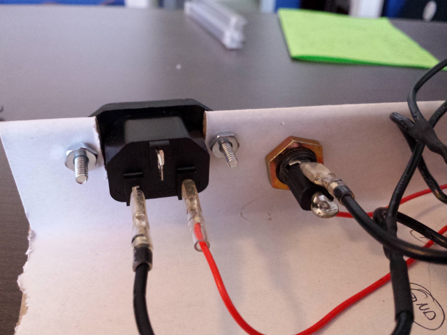
When I plugged it in on the Mimeo 1, the fuse made a humming sound for about 1-2 seconds then it stopped. I checked the voltages, and nothing now. I checked the fuse and it had blown (darkened but not actually broken). The fuse I used is a 3AG 250V 0.5A slo-blo fuse as per the Apple 1 schematics. I used an IEC connector on my PEM, and connected "live" to my on-off-switch, to the fuse, to the transformers (in parallel to each other). I connected the other line from the transformers to the "neutral" lead of the IEC plug.
I tested it again with another fuse, and same thing, it blew in 1-2 seconds - this time I noticed a small flash at the fuse.
I unplugged the PEM from the Mimeo 1, and installed a new fuse, and tested again, and the voltages look good coming out of it.
So in building the Mimeo 1, I took special care with everything. I checked continuity along the way and no issues. I solder everything under magnification, and visually inspect each joint as I do it. I've build one other homebrew computer (N8VEM), with no issues, and have build numerous other arduino projects. The only issue I had was when checking continuity was checking the LM323K. When testing the "input" to the "can" (actually to the screws on the underside of the board), my fluke VMM signaled a connection one way, but not on the same test point with leads switched. I turned it to ohms, and measured the following:
1) input to CAN: 1.3 M-ohms (or 1,300,000 ohms)
2) input to output: 1.3 M-ohms (or 1,300,000 ohms)
3) output to CAN: 1.1 K-ohms (or 1,100 ohms)
I can post a picture of my board and PEM.
Does anyone see anything that looks amiss?
I thought the 0.5A fuse was a bit small, but if that's in the Apple 1 schematic specs, then I guess it works.
Anyone have any specific areas to look for problems?
Thanks for any suggestions.
I would isolate the problem further, by disconnecting one of two transformers, say the 110 VAC-32 VAC one first.
If the fuse does not blow, it means the +5 volt circuitry is OK and the problem is on +12/ -12/ -5 volt side.
In my first Apple I clone build, I had a similar problem.
The problem was one of my regulators was installed backwards.
Check page 14 of the Mimeo assembly guide for installation details.
http://www.willegal.net/appleii/A1-assembly-v1.1.pdf
Thanks for the reply.
I checked my voltage regulators many many times against both the instructions and the visual orientation on the sample photo on the cover of my printed instructions. Separating the transformers makes sense to get more info to see what else is going on.
I'm hoping someone sees something clearly wrong in my setup, but if no-one sees anything, I'll try that.
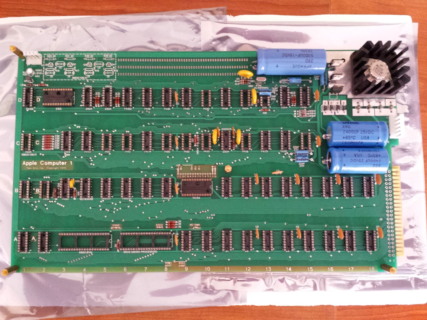
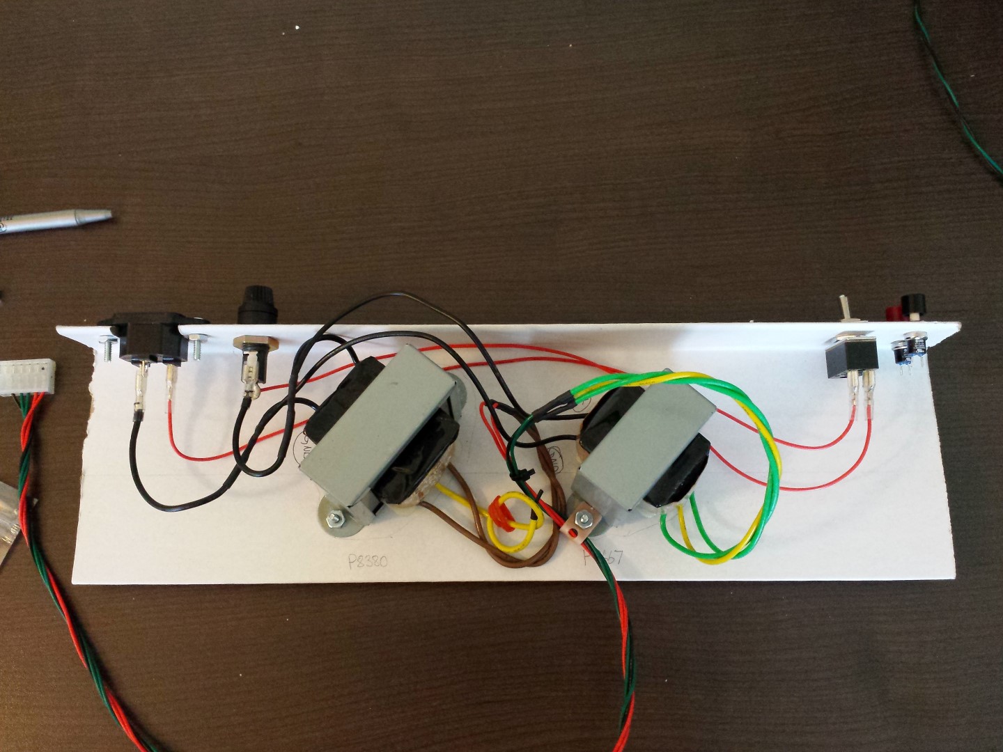
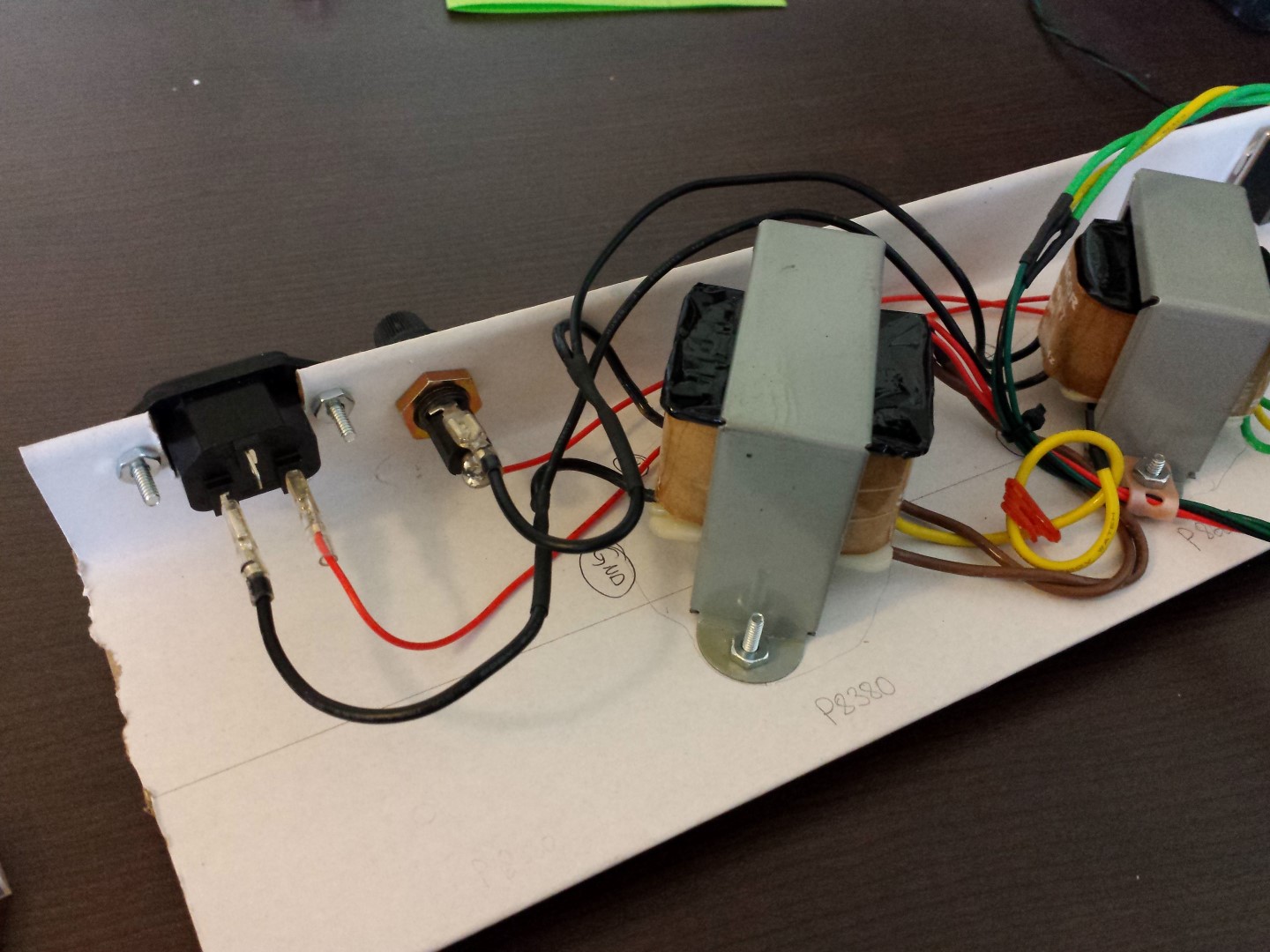
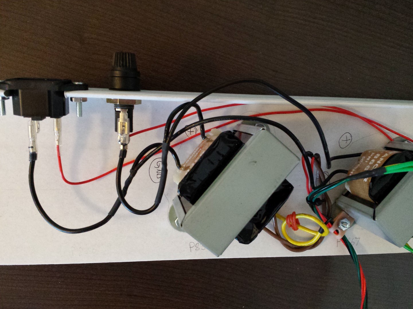
I also took some pictures of my board and the power area, and my PEM. My PEM setup is rigged up on a piece of hard cardboard (almost as hard as wood), and I've written on the board near the transformers my wired polarity. I've also color coded my wires to the Mimeo 1 to be red (output of the P-8380), green (green wires from the P-8667), and black (mid-wire from P-8667).
Thanks!
From the photos, all your primary wiring seems OK to me.
All your rectifier diodes and regulators seem to be in the right position.
Therefore, it is probably something on the board like a short or maybe defective power supply component (diode, regulator)
I would check the diodes in circuit with the semiconductor option of a DMM.
I would also recommend checking every square inch of the solder side of the board for solder bridges (shorts) with a magnifying glass. Especially at the bypass caps.
I had plenty of those before I powered up my board..
Sounds like you are testing power without chips installed, which is a good thing. I found .5 AMP slo blow fuses may eventually blow during power on surge, but without chips installed power consumption should be minimal. I now use 2 AMP fast blow fuses.
Since the fuse goes so fast, I suspect you have a short. Could be in the soldering, PCB or one of the components. Did you check for shorts between power and ground and between the different power supplies? You say you checked voltages - were they correct before the fuse blew?
regards,
Mike Willegal
OK. I just checked each of the small capacitors for shorts and did not find anything except for passing current briefly initially. I checked all the medium and large capacitors for shorts before all testing, and they all passed current briefly initially, and then stop as expected. I just rechecked the medium/large caps and they all do the same thing.
I'll work on checking all the other components. I looked over all the PCB that is still exposed with a magnifying headset (a Donegan Optivisor with 2.5x magnification with supplemental lighting) and didn't find anything. I've heard there can be flecks of metal underneath the solder mark that can short two traces that run next to each other. I looked for anything like that, and didn't find anything. I'll try again in the morning sitting at the window.
Thanks for the suggestions!
Hi Mike! Thanks for looking at this.
I pretty much followed all your steps as you outlined, including all the test points. The only thing I did out of sequence was installing the 0.1uF capacitors at the very end (because I had to wait on them to arrive).
So I just checked the remaining visible PCB for any visible abnormalities with a magnified headset at 2.5x, and didn't find anything. I checked all my solder points, and I do all those under magnification and am usually pretty careful about them, but just looked them over and didn't see anything. There are a couple of components that run close to each other, but they were fine.
I'm not sure what you mean about checking for shorts between power and ground - do you mean by checking the poles of the medium and large capacitors with no power supply attached like you describe in your bringup guide? If so, then yes, I checked this before powering up.
Also, how do you check for shorts "between the power supplies"? I'm a bit clueless about power supplies in general, but especially with transformers like in this. If you could give me specific points to check, that would be great.
Unfortunately I did not check the AC voltages coming from the transformers before plugging it in and blowing out the fuse. I was following the guide and plugged in the PEM, and was checking the voltages during the first switch-on across the smoothing capacitors as per the instructions. I was getting weird numbers, as follows:
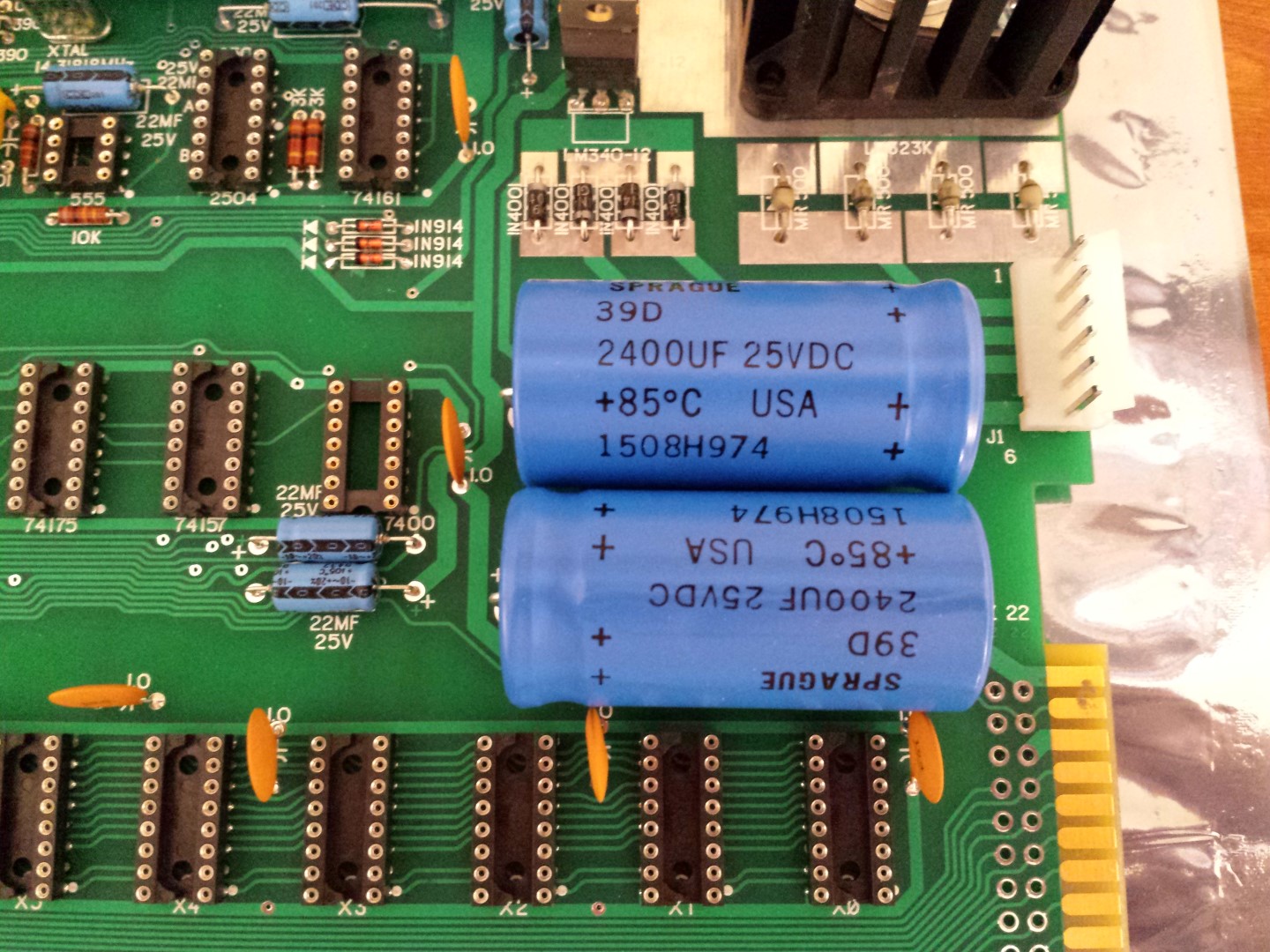
5300uF capacitor at D-15: 0.48V
lower 2400uF capacitor at C-17: 0.6V
upper 2400uF capacitor at C-17: 0.54V
all the medium capacitors were zero V
It was then that I checked the fuse, and found it was blown.
I immediately felt the components and none of them were hot and no smoke.
Thanks.
Hello Sherlock,
just two points:
the component side of the PCB is only one side of the story....
is it possible to add a picture from solder side ? It would be the second side of the story....
And just a rediculous question beside:
I hopefully guess you removed the antistic bags before performing power on ?
otherwise you might have been making a "grand short cut" at the solder side by the bags....
they have conductive coating.....
therefor a power on should be performed while PCB is placed with spacing tabs
above the table without any contact to conductive material below at solderside....
speedyG
One piece of advise.
Take a cheap bamboo toothpick and make sure you don't have any solder whiskers on the back of the board.
Also did you test your LM323k regulator before installing?
Finally as was suggested you need to isolate the problem down by only hooking up partial power. Use a second connector to "hold" the unused PEM wires.
Once you have isolated the voltage where it happenes then you have constrained your problem down and can concentrate on the areas of issue.
You also mentioned you tested continuity all the way though, but installed the ceramic caps last. Does that mean after the blues? Or were you able to test the board for continuity with the ceramic caps in place and then installed all the electrolytic. Maybe you have a bad ceramic cap?
Ok, I'll add pictures when I get home.
Oh no - I think I did test it on the esd bags. That will cause a short?
No I didn't check the lm323 before hand except to test for shorts when placed in heat sink.
I skipped the 17 ceramic disc caps, did them at then end and then retested continuity. Checked each disc cap again.
Thanks.
It sounds like a short of some kind to me.
With power off, check resistance between each voltage and ground. Also check resistance between each voltage and the other voltages. There should be some nominal resistance in each case that is greater than a few ohms.
If you find a short, then if you have a high precision ohmmeter, you can find the approximate location of the short by probing for the area of the board with the least amount of resistance. The short should be in that area.
regards,
Mike Willegal.
Post a high resolution photo of the solder side of the board, maybe we will spot something.
I guess the answer can be found in posting #9......
if the antistatic bags have been under the PCB while power on
some of the pins will have punched the antistaticbags below
and have made the shortcut
- if he now performs power on without the antistatic bags below the PCB
the shortcut might vanish.... except if he didn´t shorten the extra
portion of wires and pins that might also bend and make a shortcut too....
that´t the reason i first asked for a picture and second tried to confirm
that the bags have been removed prior to a power on...
but the bags with their conducting material has been there AT POWER ON....
( see reply in #9 ! )
speedyG
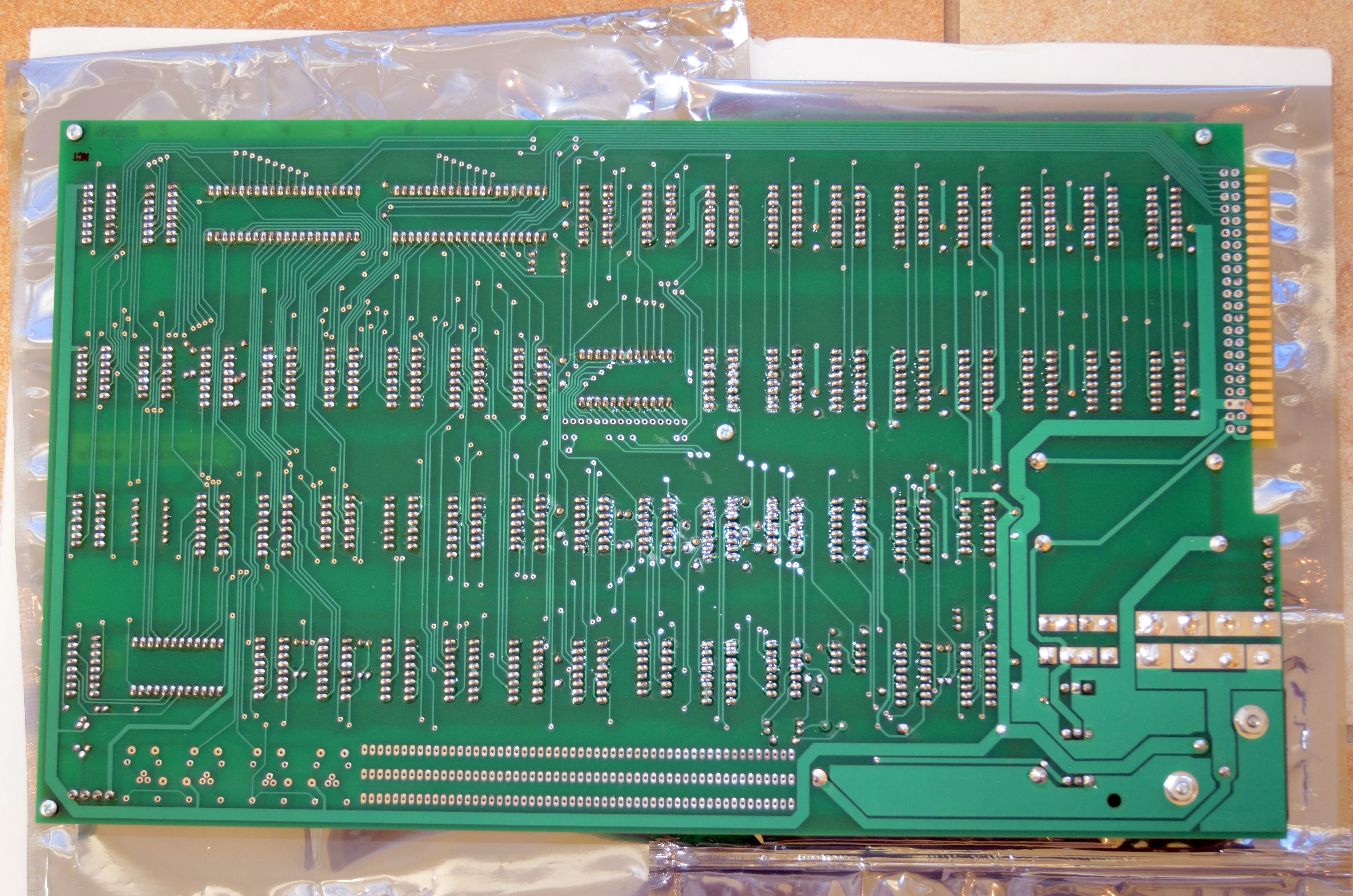
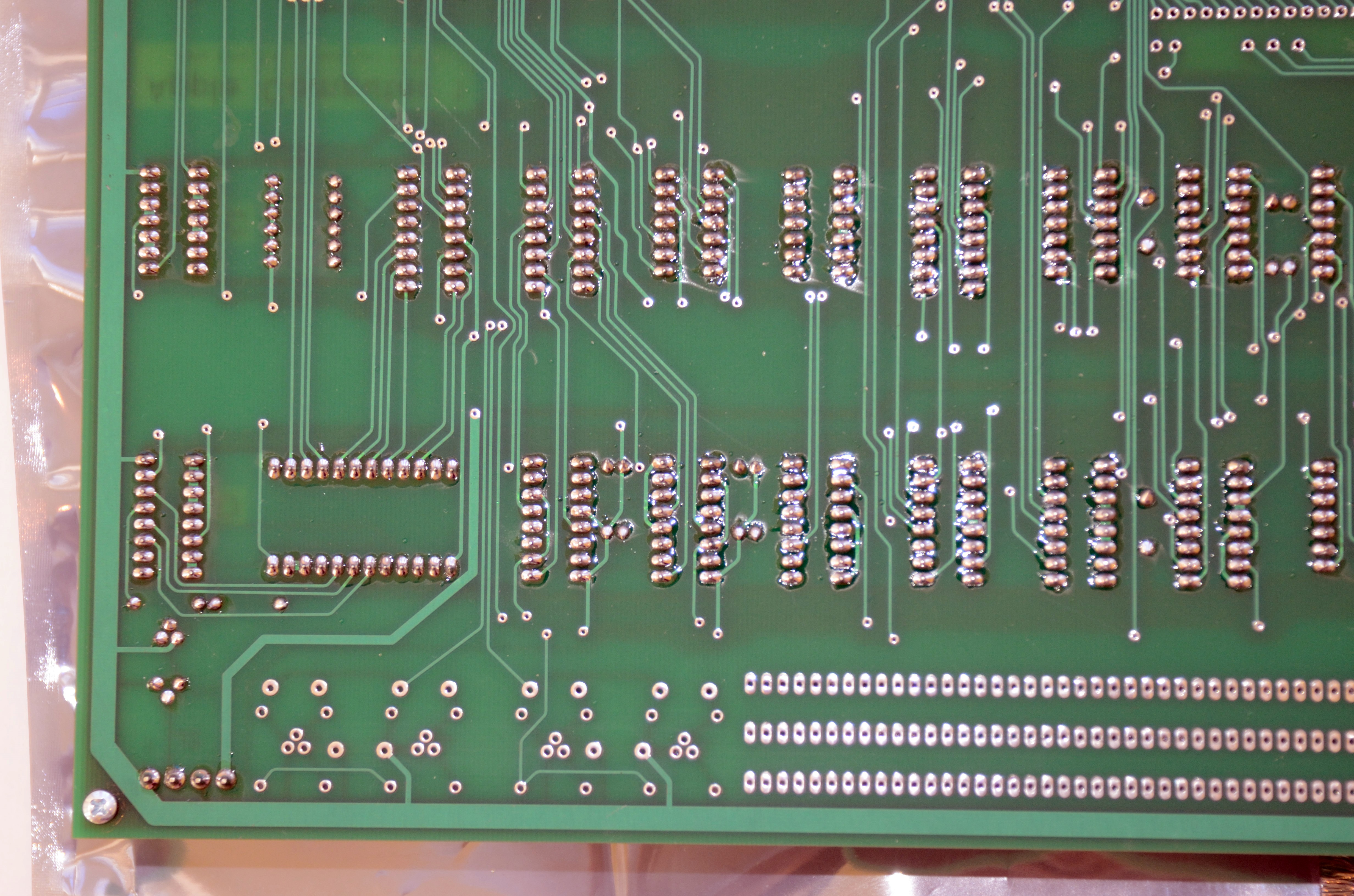
OK, so I was able to take some high-res pictures of the underside of the board. I posted them in post #1. They're called "Bottom whole", and then all 4 quadrants in more detail starting with "UL" (upper left), and then moving clockwise, UR -> LR -> LL.
I am thinking about if I did lay the board down directly on the ESD bags, and now I can't be sure. Wish I took pictures of everything as I was doing it.
I'll check all the components I can for any shorts, and then maybe try it again making sure it's off the ESD bags (I hope that's it).
I guess then I'm on to separating out the transformers and then trying to see if that does anything different. Anything in particular that anyone can think of to try while I'm testing? I don't have much time, based on my last test. The fuse blew in about 2 seconds from turning on. I guess I can immediately touch components and see if they're hot or not if that happens again.
Maybe someone will see something in the the new pictures. Like I said, I checked over it with 2.5x magnification, and looked at each solder joint under bright light, and don't see there's much of a chance of a solder bridge. I'll check over it again, though.
Thanks so far for everyone's help.
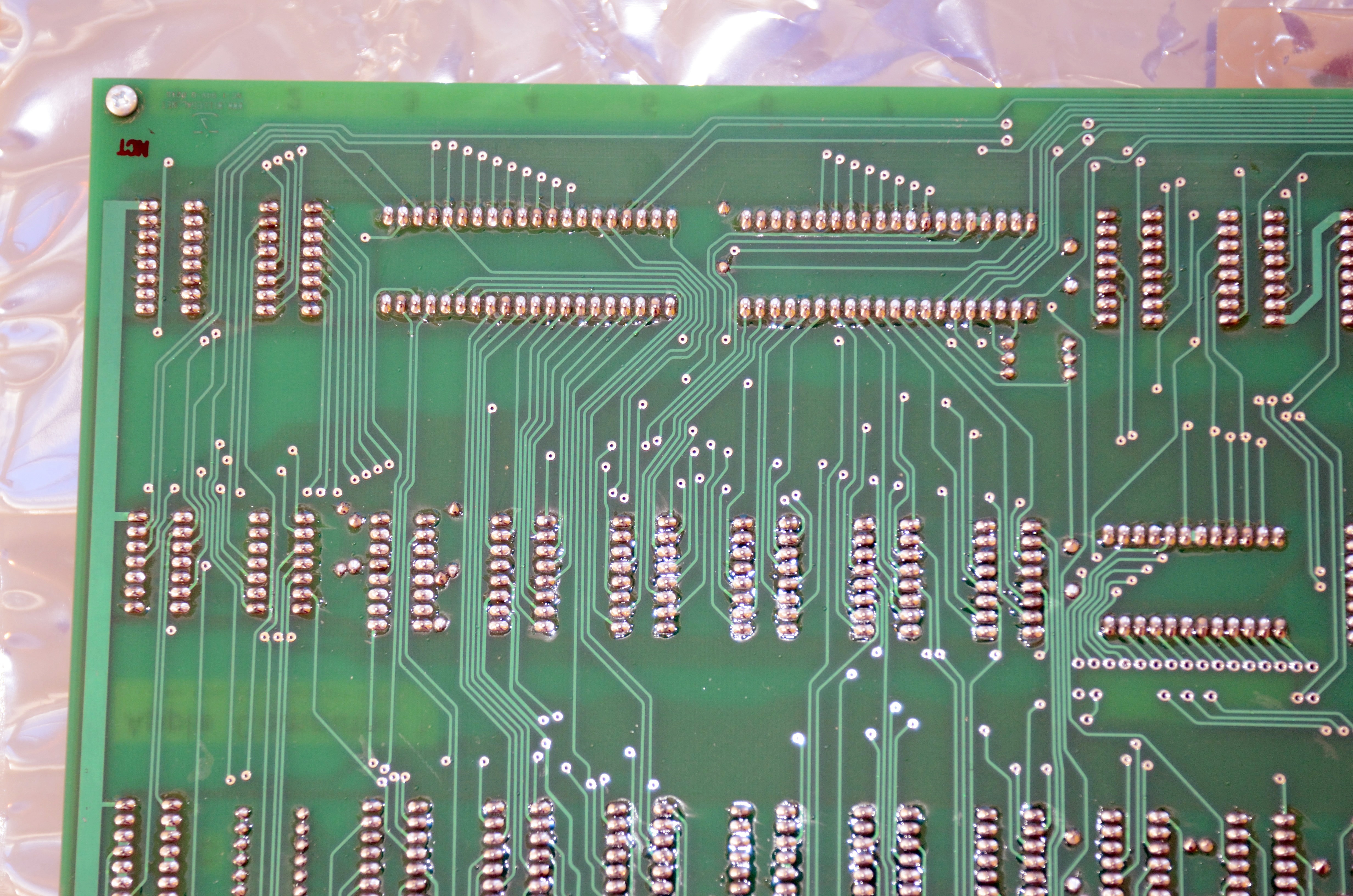
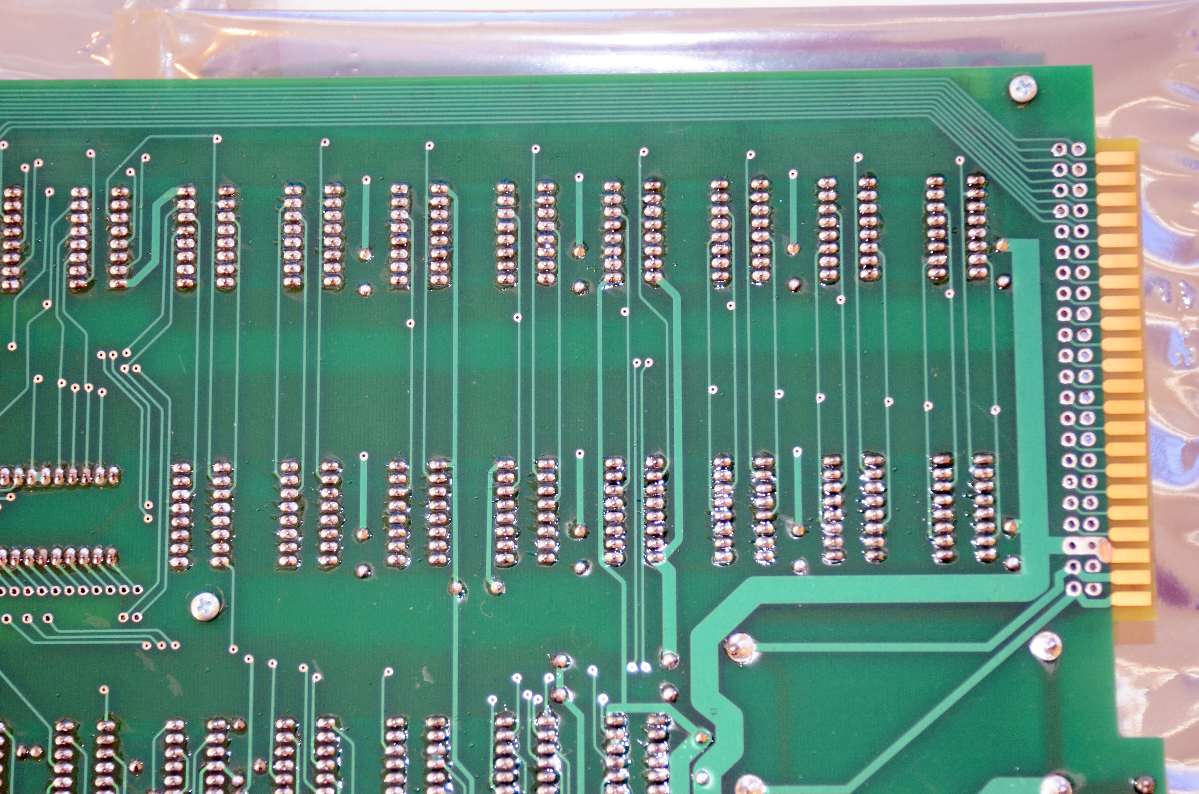
Hello Sherlock,
first of all:
at the soldering side there is still a hige amount of residine left at the
soldering spots. Besides causing multiple reflections that make a inspection difficult
that resine also permits creeping voltages ....
therefor i would strongly recommend to take an old wornout toothbrush,
and clean off that residine ( maybe aided with isopropanol alkohol )
to get a realy clean solder side.
I tried to ignore the reflections and search for possible problems...
i´ve marked them up with red arrows at this picture:
http://www.appleii-box.de/applefritter/Bottomwholework.jpg
wish you good luck with the search
speedyG
Hey speedyG,
You're kidding! Rosin flux can cause shorts? I have never heard that before. I just googled it, though, and it looks like some people say "yes", and some say "no", so I guess it's possible. By the way, I use RadioShack 60/40 rosin-core solder on all my soldering. I have built many boards without cleaning this up before testing, but maybe I got lucky and this board is a lot bigger than any of my other ones. I was planning on cleaning this PCB later, but it would probably take AGES on a board this size, and I desperately wanted to confirm it was somewhat working before I did this. I've also got a few more things to solder (the jumpers), but didn't want to do that until I had tested the power supply.
Dang, I was hoping I could test without cleaning it yet, but I guess it's the most prudent next step, if it could be causing my problems. Cleaning up is no fun, though. It is satisfying after you're done, though.
I did check your indicated solder joints with magnification and they looked fine. It is tougher to check the solder joints with the rosin on it, so I at the least cleaning it up will make spotting any solder bridges easier. Thanks for taking the time to go over my images and for the help.
I'll try testing for shorts between the voltages (which I guess I should do by checking the output pins on all the voltage regulators against each other, right?) as Mike suggested, and then if I don't find anything then I'll give the board a clean before proceeding.
I don't see any problems on the solder side.
I never had any issues with leaving rosin behind.
At this point try the following
1) Transformer (+5 volts) in line, other transformer off line
2) Transformer (+12/-12/-5 volts) on line, other transformer offline
When you find the culprit power supply, I would remove the regulator(s).
If the problem goes away, the problem is something on the output of the regulator shorting it (or the regulator itself),
else it is a problem with the rectifier or filter capacitor before the regulator if the problem does not disappear.
creeping voltages are not short cuts !
resin has some resistance..... so it´s not really bridging 2 joints, but it permits several milliamperes pass...
but if you add up all that resin it will permit larger amount of current to pass ( but i agree that the amount
should not cause the fuse to get destroyed )...
In fact i still believe that the antistaticbags caused the short cut.....
the bad thing with the resin would happen later when populating the board:
the higher the frequencies are - the more "transparent" the resin gets ( meaning the more current may pass )....
so a lot of resin will cause a lot of timing problems...
and as explained it prevents you from detecting shortcuts or other problems because
the reflections prevent you from viewing problems...
speedyG
IEEE - thank you. I'm a bit confused about if removing one transformer eliminates the problem, I need to look for the issue on that side of the power setup, and this may involve removing the voltage regulator. If I remove the voltage regulator on the problem side, it will basically be the equivalent of removing the transformer from that side of the power setup, right? The next step after this is not clear to me, but it may be no use going into that if it's not the problem. If you could clarify for my education, that would be great.
OK, speedyG, I've never heard of that, but it definitely sounds prudent to clean the rosins, but that it may not be contributing to my short.
----------------------------
One BIG QUESTION: I've been staring that these schematics in researching everyone's responses above, and I've noticed something I don't understand at all. Where is the GROUND in this whole thing? I'm using 2 tranformers (P-8380 and P-8667), and these have 2 input wires, that I have connected to my mains at the LIVE pin and NEUTRAL pin. I have nothing connected to the GROUND pin on the mains line.
Apple 1 Operation Manual PEM schematic: http://www.digibarn.com/collections/manuals/apple-1/Apple1-_Page_09.jpg
For P-8380, I have the 2 brown output wires connected to the J1 header in Mimeo at pins 1 and 2, as per the Apple 1 Operation Manual PEM schematic, and I do NOT have the middle output wire from P-8380 connected to anything.
For P-8667, I have the 2 green output wires connected to J1 at pins 3 and 4, and I have the yellow output wire connected to J1 pin 5 (which is ground from the Mimeo).
Where is the DC ground going? Do I need to connect J1 pin 5 to ground on the mains? As far as I can see, all the grounds simply go to the yellow wire on P-8667 (middle output wire) and nowhere else. Is this right?
The PEM schematic on the Apple 1 Operation Manual has all these pins connected to a ground symbol, so I presumed this was just to connect them all together and that they are symbolic of the ground. I did NOT connect these wires to the actual GROUND pin on the mains. My mains ground connector is not connected to anything, and my NEUTRAL pin on the mains is only connected to the return path on my 2 transformers.
I don't really understand how the ground system works in this. My understanding is that on the mains, LIVE is power, NEUTRAL is the return path for the power, and GROUND is usually what you connect the chassis of the device to. I do not understand how the GROUND from the DC side of things gets back to the mains.
Can someone please explain this to me. I tried googling it, but every discussion I find quickly spins into oblivion about all the infinite wrinkles of variation based on the particular application of the AC circuit, and many of them seem on the industrial level and way over my head.
HELP!
The ground is used for safety reasons only.
If your electronics are completely enclosed in a insulated plastic box (like a TV set) a ground is not needed.
However, if you device is enclosed in a conductive box (like dishwasher or clothes washer) or even have a small metal surface that could be energized in case of a fault, a ground is definitely needed in case a 117 volt fault takes place. A ground will prevent your enclosure from being energized and the ground will blow the breaker or fuse at the electrical panel instead.
Exemptions to this rule are devices like low voltage laptops and routers which use an completed insulated AC adapter.
Grounding the two transformer frames and DC ground of the Mimeo board would not be a bad idea.
Hello Sherlock,
just to explain the mystery about the ground:
within the Apple 1 PCB there is a "virtual" ground.
It results from the centerpoint between the +12 Volt regulator and the - 12 Volt regulator.
See page 11 of the Apple 1 Manual. At the centerpoint between the 2 coils of the 12 Volt windings
( marked at J1 Point 5 )and it also is connected to the minus pol of the 5300 µF Capacitor
( the largest one on top of the PCB ). But due to the fact that it´s a virtual Ground it´s a little bit
tricky.
SpeedyG
OK, thanks. This is how I thought of ground on the mains side, so this fits with how I understand it. I never thought of why it was this way, but your explanation makes a lot of sense.
OK, thanks. I found the wikipedia page on my search that discussed "floating ground" which sounds like what you're talking about. It seems a bit mystical to me currently, though, based on my limited understanding of AC. On a high level, I think of it something like "AC fluctuates between a positive voltage and a negative voltage, and the middle of this should be around zero voltage". Probably very crude compared to what's actually happening, but probably all I can manage at this point. As long as I wasn't totally off my rocker wiring it up this way, and it sounds like it's supposed to be like this.
Both supplies use four diodes each, but use different rectification schemes.
1) The 5 volt supply uses a full wave bridge rectfier configuration (which requires no transformer center tap, but needs four diodes).
2) The +12/-12 supply is actually two supplies in one.
Two diodes are used as a +12 volt full wave rectifier with the transformer center tap (ground).
The other two diodes are used as a -12 volt full wave rectifier with the transformer center tap (ground).
OK, so now I'm even more confused. I did a bunch of testing, and have some confusing results.
First, I tried testing that the voltages between the voltage regulators were not shorted together. I tried looking at the datasheets for my parts and comparing these to the schematics of the PEM from the Apple Operation Manual page 11, and nothing added up. For one thing, my LM320 MP-5 (part #MC7905) which is supposed to output -5V, lists pin 2 as INPUT, and pin 3 as OUTPUT, and says the heatsink is connected to pin 2 (as per the manufacturer datasheet). The Apple schematic says pin 2 is OUTPUT, pin 3 is INPUT, and states the heatsink is -12 ??? How is that possible?
So now I'm like, what does any of this mean? So the Apple PEM schematic refers to note #15, which states the heatsink tabs of the regulators are all at different voltages, and should NOT be shorted together. So I think, okay, finally something I can test. I test the connectivity between the heatsink tabs.
I test these, and get the following connections:
LM323 to LM340-12 : connection both ways (with red/black leads from volt-meter showing connection each way) - makes sense to me since the schematic says these two heatsinks are both GND
LM320 MP-12 to LM340-12 : connection only from LM320 MP-12 TOWARDS LM340-12 (ie. with the red probe on the LM320 MP-12 and the black probe on the LM340-12 heatsink) - this doesn't make any sense to me. The schematic says LM320 MP-12 heatsink tab is at -15V, and LM340-12 is at GND. Plus, if there is a connection, why doesn't it show connection with probes reversed. Maybe something to do with the diodes. If I understood how the regulators were connected, maybe I would be able to figure that part out.
None of the other regulator tab tests showed any connection.
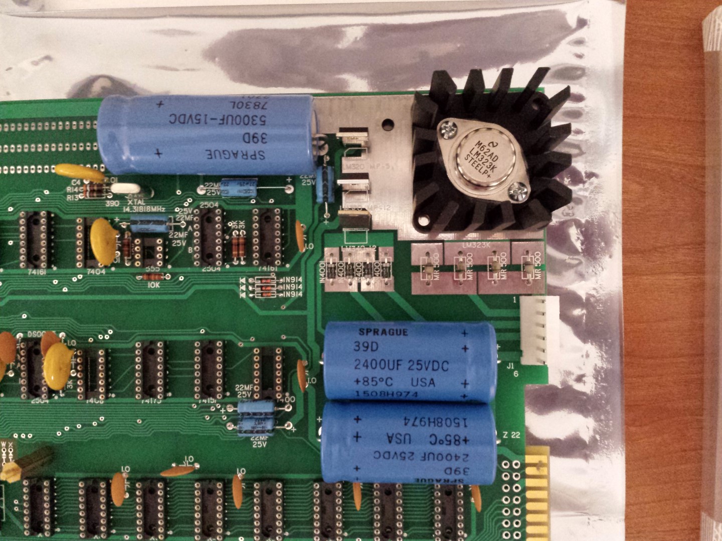
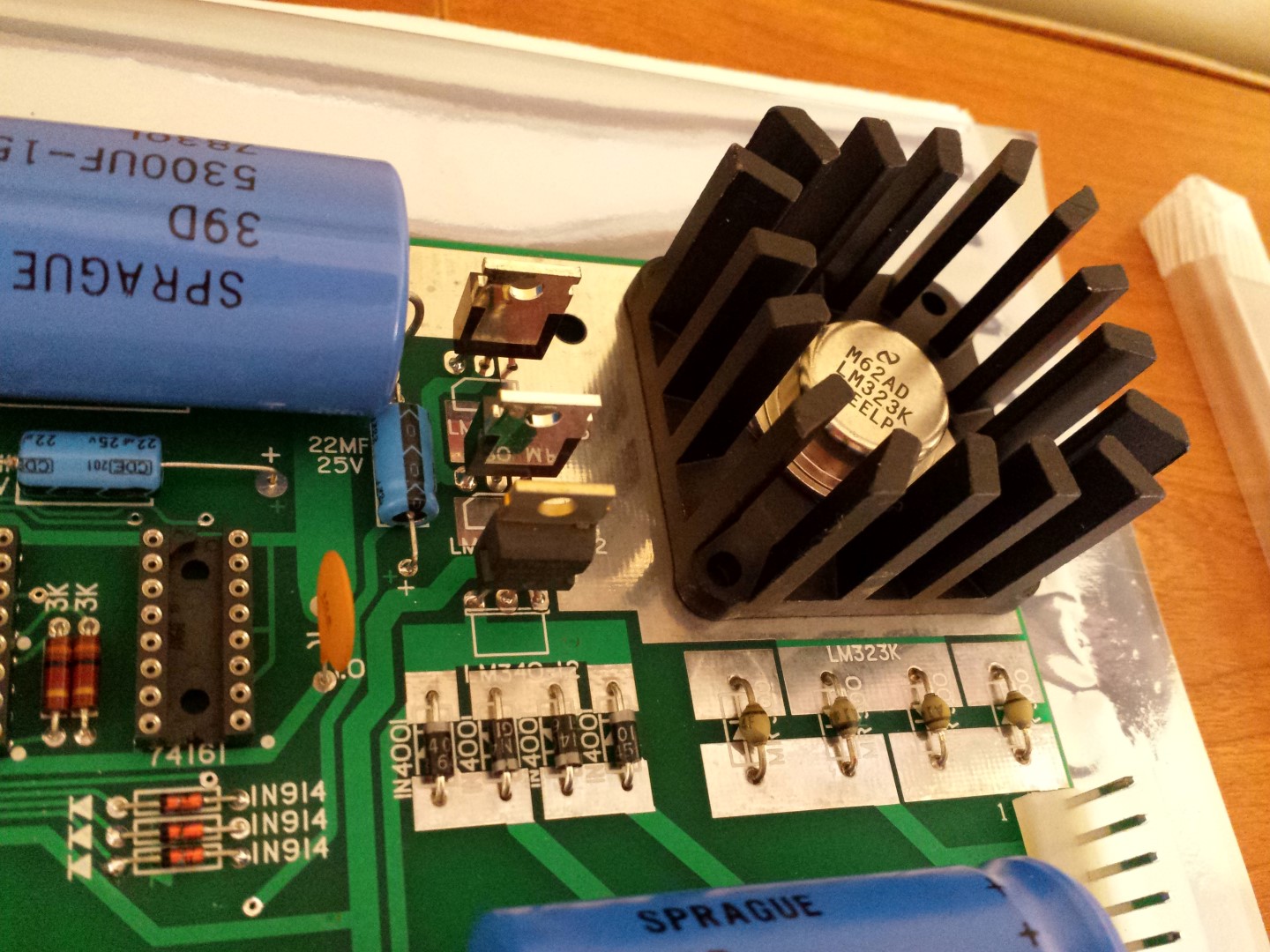
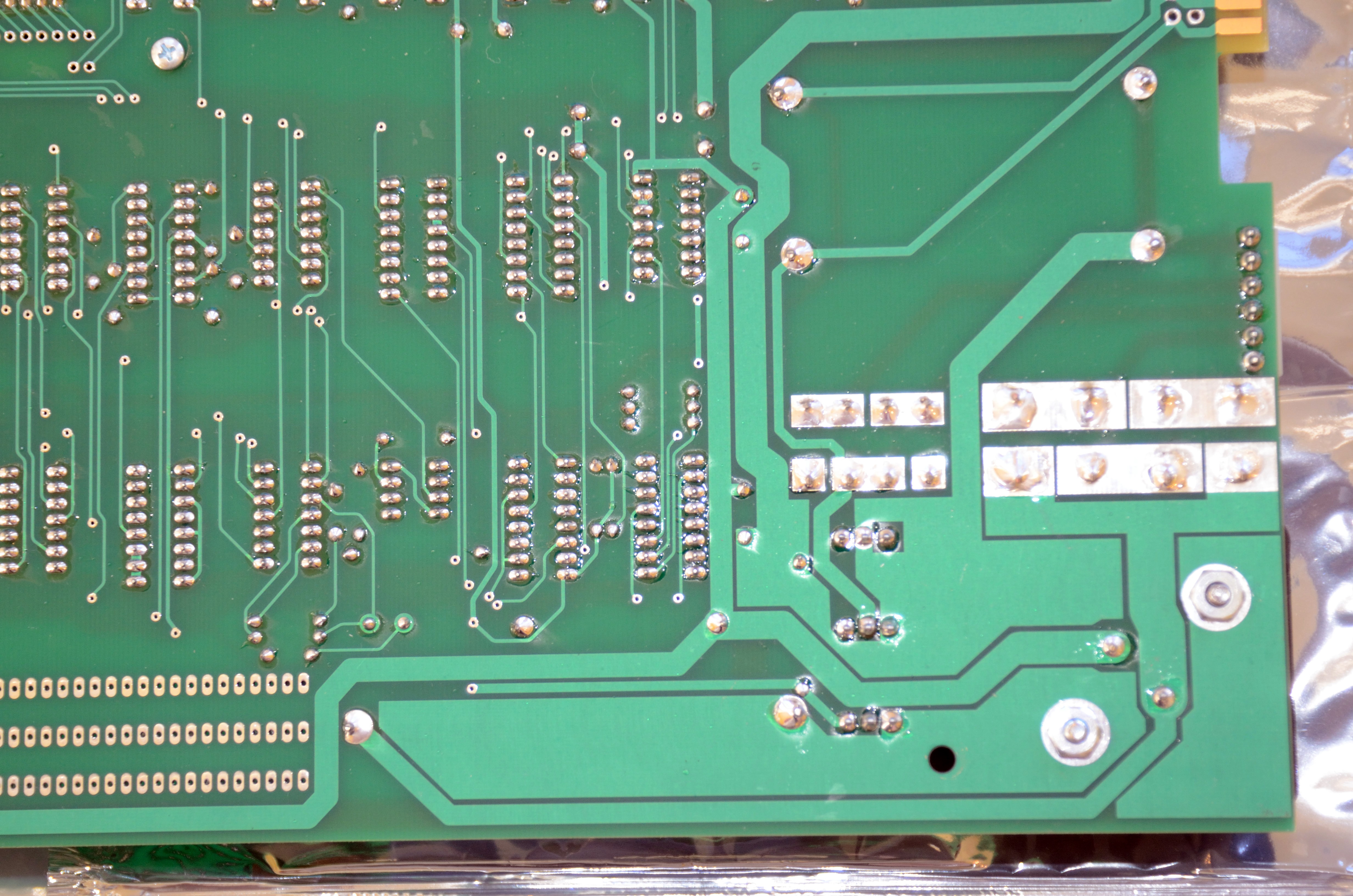
So now I'm thinking of the diodes, so I test those. With the board facing solder-side down, and with the "Apple Computer 1" on the left of the board, and the huge heatsink on the upper right, I tested each of the 8 diodes in that corner from left-most to right-most (total of 1N4001 x 4, then A14F x 4). I paid close attention to the orientation. My results are as follows ("FW" = forward test with red probe going towards black probe on VMM, "RV" = reverse test) using my VMM set on diode testing mode:
1N4001 #1: FW: 0.54V, RV: OL (open loop)
1N4001 #2: FW: 0.57V, RV: OL
1N4001 #3: FW: 0.54V, RV: OL
1N4001 #4: FW: 0.56V, RV: OL
OK, so far so good. Based on what I know about diodes, these are working correctly.
Now I move onto the A14F diodes:
A14F #1: FW: 0 with continuous beep from VMM, RV: 0 with continuous beep
A14F #2: FW: slow increase to 0.5V and then holding there, RV: slow increase to 1.23V and holding there
A14F #3: FW: 0.56V, RV: OL
A14F #4: FW: OL, RV slow increase to 0.56V
So what does any of that mean? Is #1 shorted closed? Is #2 messed up? #3 looks okay. Is #4 reversed? I double, tripe, quadruple checked the markings on the diodes compares to the silkscreen, and also against other pictures of completed Mimeo builds on the internet.
Could someone help me decipher what's happening here? Did I find something?
I just saw your response after spending a while composing my message. OK, I'll digest your comments about the diodes and their setup a little later if I can avoid doing it now. I figured the diodes help sort out the "back and forth" nature of the alternating current, since they only allow current to flow in a single direction, and the patterns of arranging these sound like they are well established based on your comments. Your explanation will definitely help me piece together my understanding of the PEM part better in the future, so thanks for that.
For 78xx (LM340) devices
pin #1 is input, #2 is ground and #3 is output
For 79xx (LM320) devices
pin #1 is ground, #2 is input and #3 is output
Pin #1 in both cases has a dimple or dot.
OK, thanks. So I should trust the manufacturer's datasheet over the Apple Operations Manual schematic. I tested with this assumption, and there were no shorts, either between the voltage regulator outputs, or the voltage regulator outputs and GND.
I did spend some time looking closer at my diode test data from my earlier post yesterday. Since I am testing the diodes in-circuit, I will need to take into account what else the diodes are connected to. So the results I got where the readings were changing probably have to do with the capacitors connected to those junctions. Therefore they are all probably OK, except for the one of the MR500/A14F diodes (the left-most one with the Mimeo PCB oriented with the huge heatsink on the upper right). From looking at the PCB leads, it's the one connected to J1 pin 2, with polarity pointing away from J1/pin 2. This diode was showing almost no resistance either way, and I retested it just now and it showed 0.3 ohms forward and backwards.
Could this be my problem? Should this diode EVER behave like this? I can't imagine anything that would cause this, other than the diode is shorted out. Could someone chime in on this, and let me know if I'm on the right track?
It does sound suspicious. You can lift one leg and recheck out of circuit to ensure that the problem isn't elsewhere. You can also check it with your meters diode checker function. Here is a tutorial on checking diodes.
http://www.allaboutcircuits.com/textbook/semiconductors/chpt-3/meter-check-of-a-diode/
These are silicon rectifier diodes so you should see roughly a .6 volt drop in the forward direction. Often, when they are bad, the measurement usually will not be anwhere near that - either complete open or short.
regards,
Mike Willegal
What was the result of testing the suspect solder shorts in:
http://www.appleii-box.de/applefritter/Bottomwholework.jpg
?
How about the one in the lower righthand corner?
Did you test the diodes with or without the transformers plugged into the Mimeo board ?
I would test the diodes with transformers unplugged. The transformer windings look like a short circuit when measured with a DMM.
OK, thanks! I read that link, and that's how I was testing it - both with the diode test function and the resistance test.
All the flagged suspected shorts in the image tested fine, including all the capacitors, and including the one on the voltage regulator on the lower-right.
I tested everything with the transformers UNPLUGGED.
Then we´re back to the diode mentioned in message #28....
it seems that my suspect on the first suspense turns out to have become true...
testing with the antistatic bags below causing a shortcut and dragging the diode to become
shortcut ....
so if the diode is replaced and the next test is performed without the bags below the test should perform fine....
speedyG
I really hope so!
I'm going to desolder one side of the suspect diode and retest it to make sure it's not anything else. If it confirms my initial test of it, then I think we have a winner.
The diode is a reasonable suspect. If it turns out to be alright, then start looking at other parts connected to it and test them accordingly.
Keatah: OK, thanks.
-------------------------
Update:
I desoldered the suspect A14F diode and tested it again. Definitely fails both using my voltmeter's diode test function (forwards and backwards), and checking resistance (0.3-0.5 ohms forwards and backwards).
Now I've got to go get the replacement, and there aren't many options since it seems to be a pretty unusual part.
Thanks everyone for all your insights and helping me with this! I'll keep you posted on the progress.
With the defective diodes out of the circuit, you should power up the board and see that the +12/-12/-5 volt section is OK.
yep ...
that makes sense, due to the fact that otherwise it´s not confirmed that the rest is O.K.
while searching for a replacement it should be performed to avoid that later another part
is missing or to be replaced when the ordered rectifying diode is delivered....
http://www.ebay.de/itm/A14F-Silicon-Diode-/161683466197?hash=item25a515e7d5:g:49sAAOSwstxVOlbT
is the correct replacement. Little Diode is a bit expensive as supplier but absolut reliable and correct.
Anyhow....
you may use also other replacement parts as "interrim solution" until you get the correct replacement
for example
1N5400
or BY550-50.
Both handle up to 50 Volt and 1N5400 up to 3 Ampere and BY550-50 up to 5 Ampere
as silizium rectifying diode in "best choice" i´d recommend BY550-50 as the better interim solution.
speedyG
IEEE: just what I was thinking!
Speedy: thanks for the compatible parts. I may very well do this, since it may take a while to get another A14F. I actually checked out the local RadioShack, and they have the 1N5400, so I may get some of those tomorrow.
-------
UPDATE! I removed the faulty A14F (the left-most one), and retested it, and it tests the same: shorted closed in both directions with <0.5 ohms resistance both ways. So we have a winner!
I hooked up just the P-8667 transformer, and powered up hopefully. I closed my eyes and flipped the switch - no hums, crackles, or pops. I waited for about 30 seconds wondering if anything was happening. I tested the test points as per Mike Willegal's bring-up guide, and hooray! I have most of the readings!
My results (following the guide order at http://www.willegal.net/appleii/A1-assembly-v1.1.pdf on page 15) is as follows:
+5V unregulated / 5300uF capacitor at D15 / should be roughly +10V --> I got zero (makes sense - transformer disconnected)
+12V unregulated / lower 2400uF capacitor at C17 / should be roughly +20V --> I tested at +22.4V
+12V unregulated- (I'm guess this is a typo and should read "-12V unregulated") / upper 2400uF cap at C17 / should be +20V (should this read "-20V"?) --> I got +22.4V here too
+5V / horizontal 22uF cap at D15 / should be +5V --> I got zero (makes sense)
-5V / vertical 22uF cap at D16 / should be -5V --> I got +5.0V
+12V / lower 22uF cap at C15 / should be +12V --> I got +12.2V
-12V / upper 22uF cap at C15 / should be -12V --> I got +12.15V
So this looks like it's working for the most part!
The only thing I'm confused about is all the readings that are supposed to be negative. I see from the schematics, all the capacitors that carry the negative voltages have the + side of the caps towards ground, and vice versa for the + voltage rails. I put the voltmeter red probe on the + side of the cap, and the black probe on the other side of the cap, and got my readings. I'm guessing I need to orient the test probes according to the circuit schematic and reverse the probes for the negative voltages - is that right?
If you allways measure over the caps from - pol to + pol with
black cable at - pol connected to the caps you will get all the time positive voltages
because GND is more positiv than the the negative voltage. Take as GND
the - pol of the Upper large 5300 µF capacitor ( black cable to that - pol ) !
Then take all other measurements with red cable to the indicated measurement points
without moving the black cable to any other spot. All valtages then are referring to GND
( which is in fact 0 Volt ). Then you will see at negative measurement points negativ voltages
and at positive measurement points positiv voltages. In Fact the - pol at the 5300µF capacitor
is the reference for all measurements in the entire PCB ( also for measurements with an oscilloscope ).
speedyG
Good to hear that the three secondary supplies are working correctly.
Before replacing any diodes on the +5 volt supply, check that the input and output to the big regulator are not shorted to ground.
Thanks! What you say makes sense - just never had an actual scenario where I had to deal with negative voltages before, so I never thought about it. Cool.
Yep. I actually checked this way back in the original post (seems like years ago)! I'll check it again before putting the new diodes in, though.
Thanks.
So another update. If you look back in my diode testing data (post #25), there's something weird going on with A14F #4:
A14F #1: FW: 0 with continuous beep from VMM, RV: 0 with continuous beep
A14F #2: FW: slow increase to 0.5V and then holding there, RV: slow increase to 1.23V and holding there
A14F #3: FW: 0.56V, RV: OL
A14F #4: FW: OL, RV slow increase to 0.56V
This is the right-most one on the PCB, and from what I can see, it corresponds to the MR500/A14F diode at the very top of the diodes in the Apple 1 Operation Manual Schematic that form the full-wave-bridge-rectifier for the +5V power line (here: http://www.digibarn.com/collections/manuals/apple-1/Apple1-_Page_09.jpg).
Based on the above test, diode #4 is acting like it's reversed! It's behaving like it's in backwards. I wasn't sure if removing the previously faulty diode would have fixed it, but I desoldered #4, and just retested it and it's still the same: it carries current in reverse, but NOT forwards. I checked it over and over, feeling I was surely just reading the polarity on it wrong (look at the 2nd attached picture in post #1). No, it's behaving backwards from its markings. So now what do I do? I could put it in so that it's behavior matches how it's supposed to work (put it in "backwards"). Or do these results mean it's potentially damaged, and should not be trusted? Could the short in diode #1 have damaged it to where it reversed its direction?
Should I just put it back in "backwards", or should I just get rid of it, and replace it with a new one?
Also, one final thing: since these four MR500/A14F diodes in question are all linked together in this full-wave-bridge-rectifier setup, can they be different diodes? Can I use different diodes for #1 and #4, and expect it to work okay? I was thinking maybe they all needed to be the exact same diode type in order to work in this. I don't want to blow it up.
Hello Sherlock,
allthough i explain at:
http://www.appleii-box.de/appleboxallabotpowersupplies.htm
the switching power supplies of later Apple models, there are some similarities
between that old analog power supplies and the later made digital switching supplies.
it might be usefull to read the small portion of text explaining the function blocks....
the similarity starts at the input (A) till to the point where the rectified voltage enters
the switching power transistor ( at E ) and at the secondary side the similarity
exists from B till D except that in the here used powersupply no chokes are requested
to filter away the high frequeny and there is no protection or feedback circuitary present like in that new
supplies... in the old supplies only a fuse is used for the protection....
Within a brige rectifier it´s recomended to use 4 equal diodes because you want them to act as
similar as possible.... but at the other hand - for simple repair purpose you must just ensure the
basic functions:
the diode must be at least as fast as the one to be replaced
( this is eas because all modern diodes are far faster than the old ones )
it must be able to handle the input voltage ( the limit of maximum voltage
must be equal or higher than the replaced diode.....
and it must be able to lock up / block reverse voltage at least equal or higher voltage
and it must be able to handle the amount of current that passes the device ( in this
case equal 3 Ampere at least but 5 Ampere is better - giving a "security boundery"....
.... and yes .... in regular repair it´s recommended to replace all 4 diodes if one of the
diodes of a bridge rectifier has blown off.....
the reason: It´s like if you have killed at execution one man standing upfront of the wall
and the other 3 guys still standing.... the one guy is for sure dead....
but you don´t know if one of the other 3 guys also caught a bullet.... not dead - but still standing...
but that guy may fall down dead few minutes later.... ( drastic compare - therefor plaese no LOL )
and if you switch back to the view of the function blocks mentioned before...
if a diode is missing in a bridge strange things may happen ... depending to the position in the
bridge.... in this current case all negativ halfwave pulses are rectified ...
but every second of the positive halfwave pulses ... though while the missing positive halfwave isn´t
present there still is small activity caused by the diode in the negativ branch dragging some current from the
capacitor....
this will cause strange measurements...
speedyG
Wow, your web page is definitely a huge chunk of information. I had no idea power supplies were so complex, but it makes sense if you think about what they have to deal with. And your comments definitely make sense to me. I was suspicious I would need to change all of them in the set, because they are all dependent on each other and closely linked together.
Another thing, in my diode test data, I was looking at the results for diode #2, and it looks weird to me (with the slowly changing voltages). I retested diode #2 again after removing the shorted #1, and it now tests normally! I guess it was the shorted diode causing the "strange measurements" you were talking about. Diode #4 though, has also been removed, and it's still testing like it's "reversed", but it may be a moot point if I'm going to replace all of them. I can definitely see that one diode shorting out may cause damage to the others in the rectifier setup.
Thanks!
So I can replace all the A14F diodes with 1N5400 diodes (can't find an easy source of BY550-50's), and I should be all set. I wonder if I would need to replace them with MR500's or A14F's in the future or just leave the 1N5400's in. I guess in order to be historically correct, I should replace them with the original part, but maybe I'll just rotate them so their labels don't show, and I'll just make-believe they're the original part
Hello Sherlock,
like explained in a former posting several months ago, the
bunch of us guys building replicas split into two different groups:
a) those who want to get a complete as possible similar setup like at the original
( looking for correct dates codes, correct TI sockets and so on... )
i for example belong to this group...
b) those who want to build a replica for extended working playing with the PCB
and who insist in durability and clean operation selecting as reliable as possible
sockets and parts.... ( prefereably new ones that are not that far aged.... )
The pictures you have published makes me think, that you belong to the second group,
because the former Apple-1 has never been equipped with modern precesion sockets....
May be you´ll spend some time at the Apple-1 pages within my site to view the differences...
so if you prefer first to have a reliable operating board you´d prefer the second group but still have the option
to switch step by step to the first group... though that will cause a lot more of difficult work ...
specially changing sockets is far too much work and risky, because traces might become damaged while
running such procedure....
but a simple switch between different kinds of diodes used in the rectifying brdge is not that
difficult change ....
at least i´m happy that the pages have been usefull....
speedyG
I think I'm a bit between these groups actually, but definitely closer to the second group, as you sensed!
In my mind, making it an almost-exact match to the original Apple 1 would probably cost more time and money than I would be willing to spend right now, and would take more knowledge than I have. On the other hand, "looking" like it's close to the original is something I would like to do. Where I was shooting for was 1) functional, 2) impressive looking, and 3) for someone looking at it from a basic eye-level and at least considering that it's original (something to show off to a mostly lay-person) but definitely not something that would fool an expert. I love the bling of gold chips, so I was thinking in the future to put gold RAM chips in, and I'd really love to get a white, ceramic 6502 and possibly 6820. I would like to get the correct date codes on the larger chips in the future, purely because they're larger and easier to read than the rest of the chips (probably replace these piece-at-a-time once I have the whole thing working, so I can simply plug it in and verify it still works, and not worry about an old part not being functional). I do like the precision machined sockets, mainly just because of how they look. They actually look more "vintage" to me than most other sockets.
My kit of parts from Unicorn came with a black edge-card connector, and I was able to find a green one online that is a closer match to the original (to my eye) for a great price, but it's got the wings, which I am planning on removing. Another problem is it's got solder eyelets. I was thinking of trying to cut/crush the eyelets to try to get them to go into the PCB, so you couldn't tell once they were soldered in. That may be difficult, though, so I may just go with the black one. The individual connectors are not compatible with each other, unfortunately, as I was wondering if I could just pull out the connectors and transplant them.
Right now, I want to put it into a cool acrylic case like I've seen some people do. I do want to try to get at least an early Apple II/II+ keyboard for it, once I get it working. First, I need to get it working, though!
Pages