
| Attachment | Size |
|---|---|
| 245 KB | |
| 442.4 KB | |
| 285.4 KB | |
| 273.24 KB | |
| 233.24 KB | |
| 243.9 KB | |
| 277.82 KB | |
| 316.42 KB |
So here's an update, for anyone out there following my progress.
I sent off my bad parts, and recently received my replacements for my bad 2504v's. They were 2504N's, so I checked online for a datasheet, and they seem to be just the same.
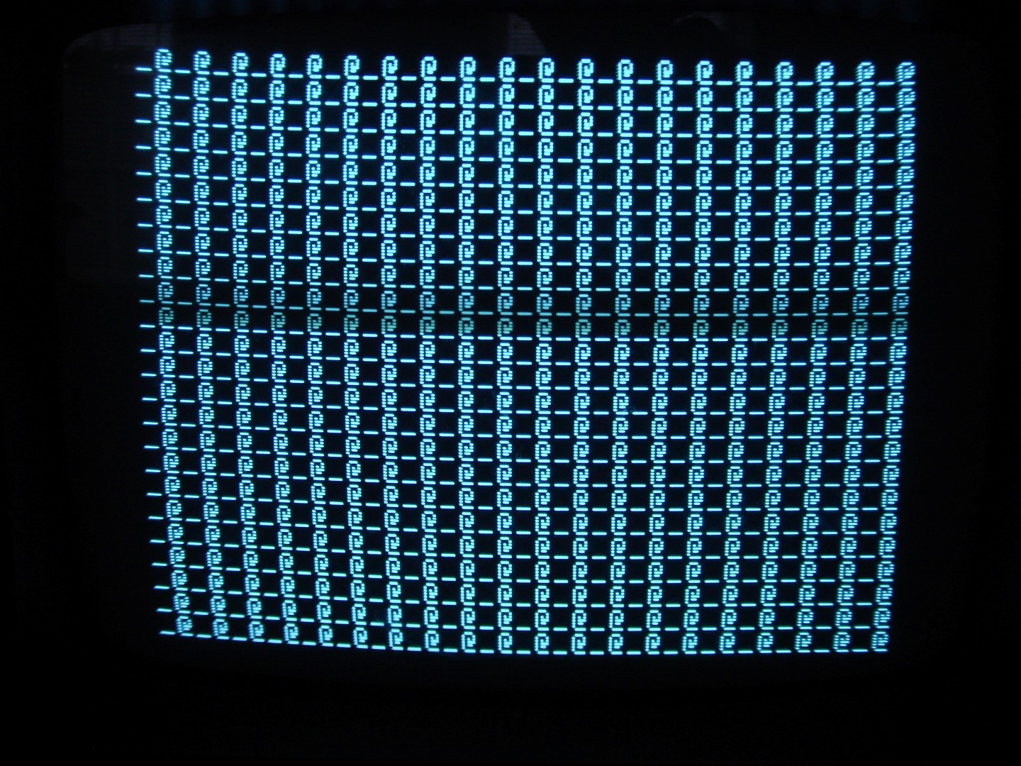
So I threw them in my Mimeo, and anxiously started it up. It seemed to work and I got a nice screen of underscores and flashing @'s.

So I excitedly turned off, and plugged all my processor side of the chips, including just the first bank of memory chips. I soldered my motherboard jumpers as recommended in the bringup manual. I had already completed my PS2-keyboard adapter, and plugged it in as well (first time).
I turned on, and still saw the correct start-up screen. I cleared-screen (CTRL C-L-R, which is pretty cool), and it went black with a flashing @ in the corner as expected. I reset the Mimeo, and got a prompt.
I typed and it seemed to work - at first. I was so overjoyed that the PS2 keyboard adapter worked, but then I noticed that not all the characters were correct.
I came back to Earth, and studied what I was seeing.
Basically I found that some of the characters worked, but then some of them would alternate between two letters if pressed repeatedly. For instance, if I pressed "A" repeatedly, it worked fine - printed a string of A's. Then, if I typed "L", it would alternate between "L" and "D", so if I pressed "L" repeatedly, it would print "LDLDLDLDLD" and so on.
Here are the keys I saw this on:
A-ok, B-ok, C-ok, D-ok, E-ok, F-ok, G-ok
H-> switches between H and @
I-> switches between I and A
J->J/B
K->K/C
L->L/D
M->M/E
N->N/F
O->O/G
P-ok, Q-ok, R-ok, S-ok, T-ok, U-ok, V-ok, W-ok
X->X/P
Y->Y/Q
Z->Z/R
So this seems quite odd. I looked at the character code mappings, and noticed the alternating characters are flipping bit 4. So "Y" is code 100110, and "Q" is 100010. Notice also, that bit 4 only flips when it is on a character where bit 4 is supposed to be a 1. So in this example, when I hit "Y" repeatedly, it prints "YQYQYQYQYQYQYQ". When I hit "Q" repeatedly, it prints "QQQQQQQQQQQQQ". So it's only flipping this bit in this situation!
So I have my theory, now what? I need to confirm if it follows the bad chip, so bit 4 is provided by the 2504 chip in D4B. So I switch everything off, and switch D4B with D4A. I switch on again, and guess what? Now all the flipped bits are in bit 3, and they only happen when the character to be printed has a 1 in bit 3. So the new results are:
A-ok, B-ok, C-ok
D->D/@
E->E/A
F->F/B
G->G/C
H-ok, I-ok, J-ok, K-ok
L->L/H
M->M/I
N->N/J and so on ...
So I think I've found another bad 2504 chip. It's frustrating that this problem didn't show itself in the startup screen, and only reveals itself in this situation. Now I've got to send this chip back and wait another week or more for the new part to come in. I seem to remember someone suggesting I get extra 2504's in an earlier post, but I tried coordinating this, but each email back to the supplier meant a delay of a day or two, and I figured coordinating getting extra chips with the replacement of the bad ones was too time-consuming, and I guess I was hopeful I wouldn't find any more bad 2504's.
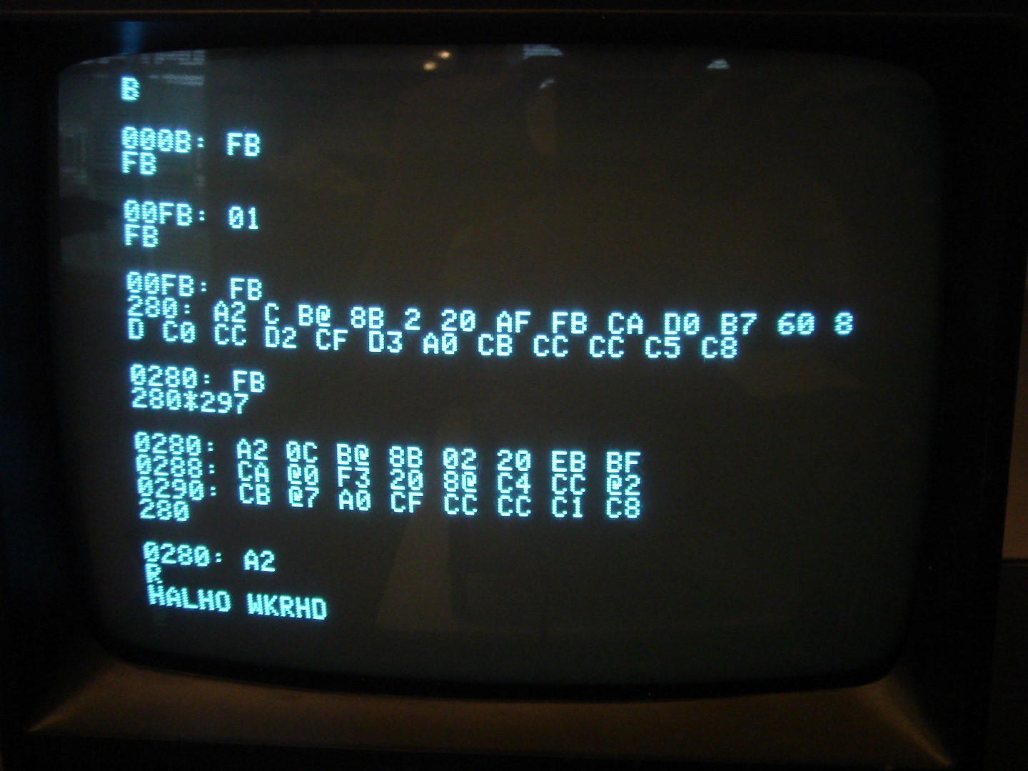
So now I think I have my problem narrowed down. I begin to play with the monitor. I display memory locations, and fiddle about with putting data into the memory locations. It seems to work, but it's really confusing because everything on the screen has alternating flipped characters according to the above scheme! I've been aching to try this Mimeo out, though, so I poke around, and it seems like the correct data is finding its way into the memory, and the instructions are working correctly, despite the flipped display characters.
So to test this, I enter a "Hello World" program. Here's the program I entered:
280:A2 C BD 8B 2 20 EF FF CA D0 F7 60 8D C4 CC D2 CF D7 A0 CF CC CC C5 C8
So what is the result? Look at this!

It works!!!! So everything I'm typing is being recognized by the Mimeo correctly, even though the display of it is messed up. Notice the weird display flipping characters, and the effect on the program output and the listing of the memory dump! It is consistent, though.
So now a waiting game, and on to the next stage!
Hello Sherlock,
anyhow congratulations up to this point.....
and yep... you should at least have 2 spare 2504´s on the shelf for spare....
that bastards have the ugly behaviour to die fast and hard....
and the period for waiting upfront a not correct working system is really boring....
i´d also recommend to have at least 2 x 4096 chips spare too.....
and if you have the chance to get a spare DS0025 you should grab that guy for spare too....
that DS0025 is far too expensive and very very difficult to get.....
you will enjoy one day in future if you took care of that few spare parts !
speedyG
Congratulations on getting to the working _@ stage
Testing the keyboard output is quite simple.
You need a logic probe ($10 item) for TTL signals.
The last character sent by the keyboard can be read out from the 6820 parallel inputs from the keyboard.
I would be surprised it is was a keyboard issue, since you were able to enter your test program.
I would bet on badly bypassed power lines to the DS0025 clock driver once you rule all 2504 devices.
If you scope the powers lines. I remember one of them being extremely noisy (spikes of several volts)
This can be solved by installing a 0.1 mfd capacitor (or 10 mfd tanatulum in some cases) between the noisy power rail and ground
This is a known design deficiency on the Apple 1, even Woz is not perfect
speedyG: yeah, I'm thinking I need to get some backups - thanks for the component suggestions.
IEEE: Thanks! It seems like my keyboard input is okay, since the program does work. I was trying to test my RS232 input on the PS/2 Keyboard adapter, but couldn't get it to work right with sending a text file over. For some reason it stops after about 8-10 characters and garbles it. When I type from the terminal program on my host PC, it makes it through okay, but when I send a file, it messes it up. I'm still fiddling with it. I just downloaded the terminal program (RealTerm from SourceForge), and its interface is a bit clunky to me, but it was the first terminal I found that allowed me to send a text file. I don't have a oscilloscope yet, but if I continue to have issues replacing the bad 2504, I'll definitely look at adding these caps.
So as I'm doing more testing, I'm noticing a few things:
1) sometimes when I turn on, on the start screen there is sometimes a row of characters going across the screen of _@'s (I think they are "X"s), and sometimes this changes if I hit keys before clearing screen and resetting. Not sure what this means. When I do clear screen, it clears normally, and appears to work normally. Has anyone else seen this and do I need to worry?
2) I last had my Mimeo on for 30-60 minutes, and was touching components before turning off, and I noticed the LM323K/heatsink is really hot - hotter than I expected. It's not scalding hot, but it's hot enough to where I can't touch it for more than about 1/2 second without discomfort, and I definitely could NOT hold onto it for an extended period. I don't have any fan connected yet, and the Mimeo is sitting on a table on 1-inch standoffs to distance it from the table top. Should I worry about this?
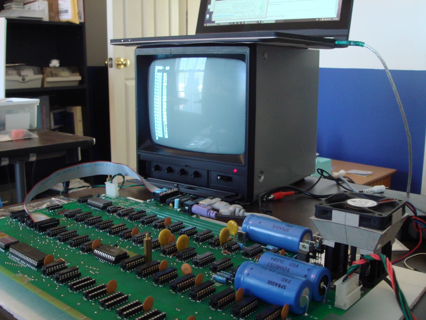
I also switched to a nice 9" B&W monitor from eBay (a Sanyo VM-4509 knock-off) which works really well. I got it for about $50 delivered, and it works wonderfully with a nice clean image. It's a much more economical option than the $200 that the Sanyo 9" monitors are going for nowadays. I like it much more than my Apple 13" color monitor (which just seemed too big for my Mimeo), and my Samsung Syncmaster LCD (which I commonly use for my legacy systems since it supports so many input types).
Hello Sherlock,
I´d recommend to follow up the suggestion of IEEE-802,
this is a often known issue.... It really is recommended to add between
the +5 Volt rail and the +12 Volt rail some filtering capacitors.... to
eliminate the spikes and noisy interferences....
and it´s also known well, that the cooling sink for the LM323K is poorly
calculated..... just a hint: I solved that issue by placing a really good fan
that i took of from an old 486 IBM Cloneboard and mounted it on top of the sink
taking the power of from the + 12 Volt rail. If you take a bit time there is a
good chance to find such a fan at the recycling yard.... the good one´s used in the
90´s demanded for +12 Volt and 0,2 Ampere.... if you are lucky such a fan still is
mounted to a plastic frame that you might install removable on top of the sink
blowing down towards the chip and the bottom of the heatsink....
and if you later like to display the system to public it will be easy to remove
the fan temporarily.
speedyG
The PS/2 adapter's RS232 does not support flow control. Your terminal program needs to have a character/line delay configured - there is a recommended value in the PS/2 adapter instructions. I wouldn't worry about the characters on the screen after power on, as long as they clear and you can enter characters via the keyboard, you are good. I'm thinking the hot LM323 heatsink is most likely OK if it's not scalding hot.
regards,
Mike Willegal
- I saw on Mike W's website that he talks about the -5V line being really noisy, and may need a higher capacitor at B13 to decouple this. You are suggesting adding a capacitor directly between the +5V and +12V lines? I've never heard of this.
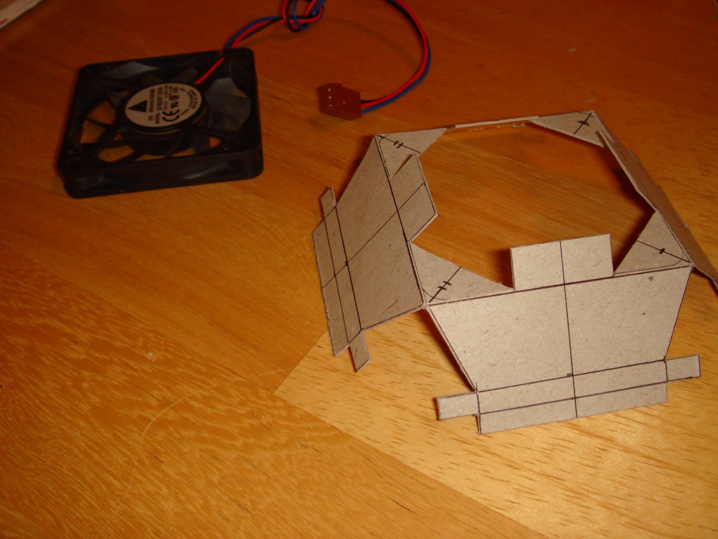
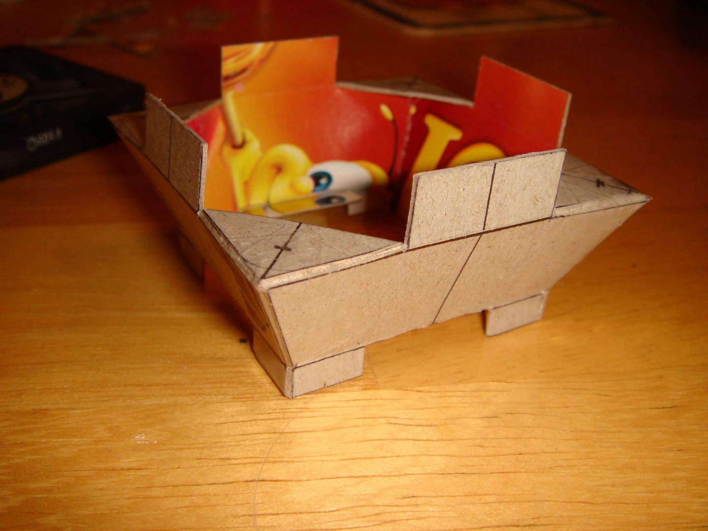
- Good idea! I was thinking I would need to do this, as long as this wasn't abnormally hot, and it sounds like it is not. I actually found a 60mm x 60mm PC 12V fan in my parts box, and tested it and runs fine, although was a bit dusty. So it's okay to run this off the 12V power line on the Mimeo? I have heard that the power supply of the Apple 1 was minimal, and was a bit worried about pulling an additional 2+ watts with the fan. Sounds like this is okay, though. I cut up a fold-up duct last night to mount the fan over the LM323 heat-sink, and it seems to fit just right, and is not permanently attached to the Mimeo. It was pretty fun to build, and I'll post pictures of it when I get home tonight. It basically is a cardboard duct that funnels the 60x60mm fan down to a 45x45mm square, and fits neatly over the top edge of the heat-sink.
- OK, thanks. I read the PS/2 adapter manual about the terminal program settings, but missed the part about the delays. I guess it was going too fast for it, so I'll try adding those delays the next chance I get to test. I also can't rule-out my cheap Prolific USB-to-Serial adapter. I also tried sending files with my WinXP laptop, which has a real serial port, but that also didn't work, but produced similar results without the delays put in, so I'll give that a try, too.
Yeah, the heat-sink was definitely hotter than I thought it would be, but like I said I can hold it for a split second - just cannot touch it for an extended period. The diodes that feed the LM323 are also quite warm, but again not scalding. I'm going to try out my new fan on the heat-sink and it should help.
I'm getting closer!
Hello Sherlock,
please excuse that the text was that way that it can be misunderstood....
of course i was meaning between :
+ 5 Volt and GND ....
and additionaly ....
+ 12 Volt and GND.
2 caps in area location D14
and 2 additonal caps at area location between D4 and area at D5
and if needed also at area location between C3 and C4.
( refering to the mainboard markings at the outline !)
Fan power use: the + 12 Volt is limited to 1 Ampere by the limits of the semicunductor....
the mainboard uses about avg. 0,4 to 0,6 Ampere depending to the amount of RAM on Board
so there is some 0,3 0,25 left that might be used without too much trouble....
... and the fan itself ? well there have been u wide bunch out there in the 90´s......
some had good ballgears and used far less power than the cheap ones from taiwan...
you should search for such a "low power" unit with good ballgear low power drag
and medium fanspeed.... something similar to this:
http://www.jameco.com/webapp/wcs/stores/servlet/Product_10001_10001_2125878_-1
the only problem might be, if the voltage regulator ( LM340-12) remains still without cooling sink
....it might get hot tooo...... but small removable coolingsink are availiable that fit in
space and that you can just clip on top with flexible fitting like this examples:
http://www.jameco.com/webapp/wcs/stores/servlet/Product_10001_10001_2178689_-1
or:
http://www.jameco.com/webapp/wcs/stores/servlet/Product_10001_10001_1933152_-1
or:
http://www.jameco.com/webapp/wcs/stores/servlet/Product_10001_10001_1115221_-1
speedyG
OK, thanks for clarifying. That makes sense to me now.
Actually, the old fan I found is almost exactly like the one you linked to.
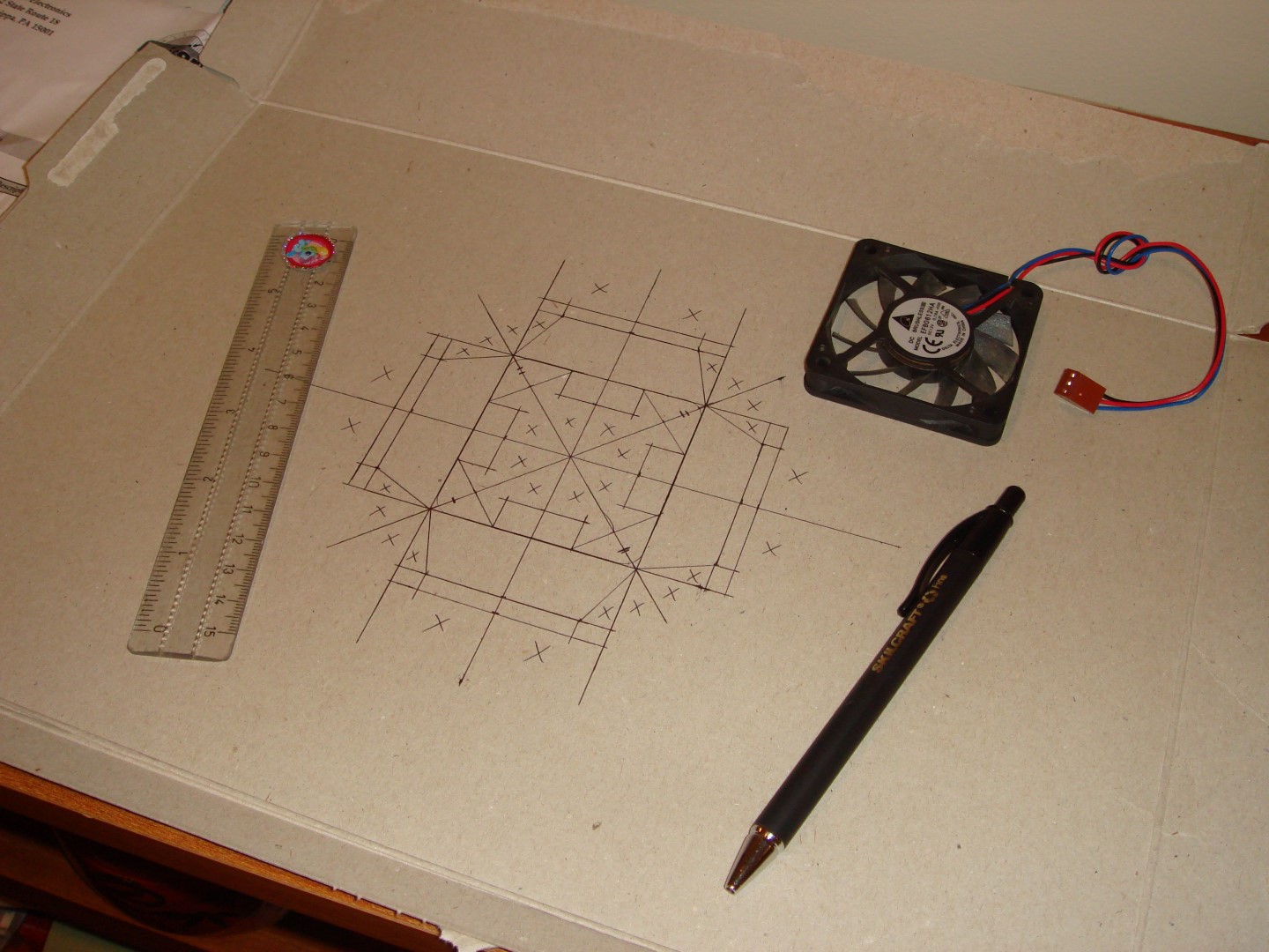
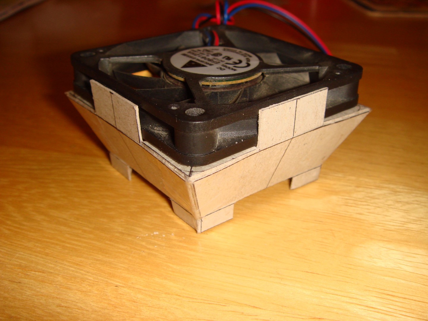
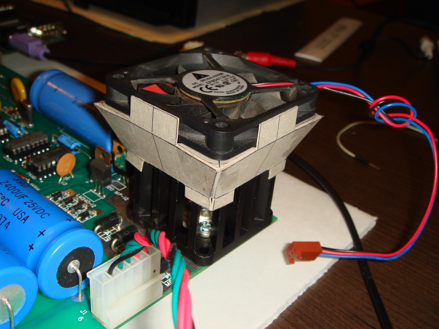
As promised, here are pictures of my heat-sink fan setup:
Basically, I drew it out on an old cereal box, and cut it out, and taped the key parts together using strong packing tape. Haven't turned it on yet, as I need to rig up the power lines.
Hmm, I'm a bit worried about piggybacking it off the Mimeo power, despite the fact the numbers seem like it will be okay. At least for testing, I've got a spare small power supply that will output 12V, so I'm going to connect it to this until I've got my Mimeo tested and working fully. Last thing I need is another power variable that may cause problems in my testing.
Hello Sherlock,
well that fan is far larger than the one i placed a link to....
the small 486-fans and small pentium fans are nearly same size
in diameter like the heatsink or only 1 cm more in diameter.
the label of this fan should display powerdisaption of that fan
in 0,xx Ampere..... or xxx milliAmpere....
this large beast is for sure better served by external powersupply.
speedyG
Hey speedyG: Actually, the fan you linked to is larger than this one (shortest side of the fan you linked to is 2.56 inches, which is 6.35cm, and its depth is 1 inch).
My fan is only 6cm x 6cm x 1cm, and the heat-sink on the Mimeo is 4.5cm x 4.5cm. This fan is 12VDC and 0.18A, so it should work, based on your earlier calculation.
I guess the pictures make it look bigger.
Hello Sherlock,
the data from your fan is realy fine....
seems the adaptor construction pictures realy tricked me.....
thanks though for the pictures ...
several other guys tinkering around with the Mimeo will be gratefull
for this inspiration of solving the adaptor fitting....
speedyG
The +5 volt regulator does run hot normally, dissipating a few watts.
It will leave burn marks on the PCB underneath, if left on long enough.
I like the small 12 volt fan idea.
On my clone, I simply anchored it to the heatsink using two plastic standoffs (normally used for anchoring PCBs to metal chassis's).
There is a 1/8 to 1/4 inch gap between the fan and heatsink, but the airflow was is still sufficent to keep the heatsink at room temperature.
speedyG: I hope it helps someone else out there thinking about the same problem. I probably got a bit carried away with making it, and I'll probably have to come up with a more permanent solution once I get my case situation worked out. I know - a water-cooled CPU radiator! The only thing for anyone else looking to do this mod, is once you've got your design drawn out, make sure you score the cardboard before bending it. That's where you run a knife edge over the line you intend to bend it to cut it about half-way through. That way, when you bend it, it's a nice clean bend. Make sure you don't cut all the way through.
IEEE: In that case, I'm glad I've got the fan now. I was thinking mine definitely gets hot enough to possibly cause problems. I probably got a bit carried away with the design, though, and certainly there are lots of solutions for this.
So my "Part 3" isn't finished yet! So as of now, I've got the 2504v corresponding to bit-3 of the display characters pulled and going back to Unicorn for replacement. Encouraged by my "HELLO WORLD" test, I decided to work some on the serial connection through the PS/2 keyboard adapter.
I decided to stay with RealTerm, because it had the most capabilities that I saw, and I figured out how to default the terminal settings. It also allows putting in delays, which none of the other I tried allowed me to do. And it's open source, which is always nice.
I put in the delays you talked about, and it worked great! I was so happy, I decided to upload the memory test program from your website: http://www.willegal.net/appleii/6502mem.htm
I uploaded it successfully, and ran it, and it worked! All my memory tested OK ($03A2 - $1000) on my 4K machine:
And I'm also happy to report the heatsink cooler fan does a great job of keeping temperatures under control.
So now, I'm thinking what is involved with moving up to 8K? I think the process is as follows:
1) remove jumper from X to 0
2) add jumper from X to E
3) add row W of memory chips
and that's it?
From what I have found online, the above changes will move my memory up to $E000 thru $EFFF (but this is only 4K - where is the other 4K? Still back in $0280-$0FFF ?) I'm not really sure how the motherboard jumpers work, and have not been able to find any info on them online on in my readings. Can someone point me in the right direction?
Just to comment on the fan thing. Been meaning to chime in but been nuts at my day job.
You really don't need a fan on the board if it's on standoffs and not in an enclosure. However I do recommend using a fan anyway not pointed down at the regulator but blowing across the heat sink and across the other regulators. They can get hot also. This way they all get a steady stream of air and the rest of the board gets some ventilation also.
And a comment on the memory. You can simply add 4 more K of memory. The changes to the jumpers are to load basic since it is not intended to be loaded into contiguous memory with the first 4K. It's intended for E000. You will also need to put the jumper in for the select of the Apple Cassette Interface.
Cheers,
Corey
Corey: OK, thanks for the suggestions. I'll definitely keep that in mind when I move on to the enclosure part. I've got your beautiful acrylic enclosure design on my head since I saw it, and can't get it out! Really a beautiful piece of work. Regarding my heatsink fan, I found that my LM323 heatsink was getting very hot even outside of an enclosure, and I just wanted to control this as much as possible. I actually have the fan blowing up, to draw the heat away from the board and suck air in the sides of the heatsink. Seems to be working well, as now the heatsink barely gets above a very mild warm.
----------------------------------------------------
So, I'm trying to figure out the jumper section in the middle of the Apple 1 board. It's something I've never really understood.
I found this map of Apple 1 memory online:
$0000 - $00FF: Zero page: location of single or double byte values used by programs
$0024 - $002B: Zero page locations used by the Monitor
$0100 - $01FF: Stack: used by the 6502 processor as a temporary holding place for addresses or data
$0200 - $027F: Keyboard input buffer storage used by the Monitor
$0280 - $0FFF: RAM space available for a program in a 4K system
$1000 - $1FFF: RAM space available for a program in an 8K system not using cassette BASIC
$C028: Port for output to cassette
$C100 - $C1FF: ROM program used to operate the cassette interface
$D010: Port where a byte of keyboard input appears
$D011: Port to indicate that “return” key on keyboard was pressed
$D012: Port to output a byte character to the display monitor
$D013: Port to cause display to skip down to the next line
$E000 - $EFFF: RAM space available for a program in an 8K system modified to use cassette BASIC
$F000 - $FFFF: PROM (programmable read-only memory) used by the Apple Monitor program
Cross referencing this with the instructions from Mike W's bring-up guide would lead me to believe that:
Y = beginning address of the PROM (usually jumpered to "F")
Z = beginning address of the PIA addresses (usually jumpered to "D")
X = beginning address of the X-bank of RAM (usually jumpered to "0")
W = beginning address of the W-bank of RAM (can be jumpered to "1" for $1000, or to "E" for $E000 for BASIC)
Can someone tell me if my assessment of the above is correct? How do the R, S, and T jumpers work?
Hello Sherlock,
so for better understanding let´s just repeat some facts:
1. the Apple-1 is "hardware" coded ( meaning that every piece of hardware is selected by a adress to a
adressing range selected by a soldered hardware wire on board.
2. the first part of this "hardwired" selection is performed by the selection of mapping the hardware in
the mainboard
and it´s slot
by use of the 74154 that splits the adressable memory ranges of 4 k because its a divider 1 to 16
( resulting from the math op: 64 kb total adresseble range of the CPU divded by 16
= 4 kB adressselection range =
16 ranges each 4 kb named from 0 to F )
accessable in the lower row of solder-holes closer to the 74154 !
3. the second part of the selection is performed by a thing you might call "selection-lines" which
represent - by alphabetic letters - the devices ( from left in top row a line more away from the
74154 decoder to the right of the row:
Y = PROM on Board default wired by solderdrop at F ( resulting to adressrange F000 to FFFF )
Z = PIA ( 6520 ) on Board default wired with short wire to D ( resulting to adressrange D000 to DFFF )
R = line availiable at slot and used by the Apple Cassette Interface ( this is wired to C )
( resulting to adressrange C000 to CFFF )
S = line availiable at slot
T = line availiable at slot
W = line responsible for lower row of RAM chips in row at location of A row and marked as W0 to W7
and this is wired by default to E as RAM load area for Basic from Tape
( resulting to adressrange E000 to EFFF )
X = line responsible for upper row of RAM chips in row at location of B row and marked as X0 to X7
and this is wired by default to 0 and used by programs as "workspace program memory )
( resulting to adressrange 0000 to 0FFF )
so i hope by this explenation the users of the MIMEO and other clones understand the reason for the wires used for encoding the hardware and the resulting adressing ranges.
sincerely
speedyG
Thank you for the very thorough and complete answer! That's exactly what I needed. It now makes perfect sense. I've always wondered how the address to activate the Cassette Interface was determined, and now it is clear, among many other things.
This information should be posted somewhere in some official documentation or a page of Apple 1 FAQ's. Thanks again!
Brief Update for those who are interested in the technical explenation how this works:
The 74154 (datasheet ) is a 4 to 16 decoding chip.
It´s inputs are named:
A ( is connected to adressing line A12 )
B ( is connected to adressing line A13 )
C ( is connected to adressing line A14 )
D ( is connected to adressing line A15 )
as binary part ( 1 Bit ) of a hexadecimal adress from the CPU ( higher byte of 2 Bytes )
and depending from that input it switches one of the 16 outputlines 0 to 15
to "low" state while the other 15 lines remain in "high" state
meaning that "low" state = 0 Volt and "high" state = 4,8 Volts.
This means if someone wants to activate a specific Interfacecard at the slot he must
detect if the line R, S or T is dropping from high state to low state.
hope that this serves good enough to explain technical detail to those
interested in the electronic function.
remark: the link is to the "more modern" kind of 74154 that was later also made in "slim"
Dual In Line case.... the previous case ( wider like Eproms ) had the same order of it´s
pins ( so called "pinout" ). The other way of explenation is to view the so called "function table"
at top of page 2 of the datasheet.
speedyG