
Hello,
I am new on AppleFritter and I wish I had discovered the Apple-1 forum before I started the adventure of builing a Apple-1 reproduction computer :-)
Anyway, while testing my work I was actually surprised that it didn't blow up in smoke LOL, however I did soon find a few issues with voltages not matching Apple-1's Operation Manual.
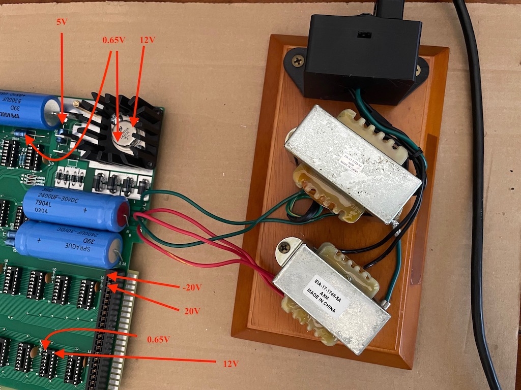
1) Most 5V connections read 0.65V across the board including on the ACR cnnector, but per example the LM320 or the video connector (1) reads the correct 5V. So, I replaced the LM323 since it came in pack of two from China, but that was even worst and read 0.25V instead of 5V. I think the problem may still be LM323 related, but I am not sure. (see attached photo)
2) The voltage is too high on PIN Y read 20V & Z read -20V from ACR connector (should be 12V and -12V), could this also be related to a bad LM323K or am I missing something here? (see attached photo)
Note: I've ordered a 3rd LM323K, this time from a US seller. (Fingers crossed)
Any advise or help on the subject is very much appreciated, Thank you in advance.
You never state what point you used as a ground reference (black probe). One place you can clip onto for ground is the (-) side of the 5300 uF cap. I mention this particularly because you say "The LM320 reads the correct 5V" but neither of the LM320-MP5 or the LM320-MP12 should have a positive voltage on either input or output; they are negative voltage regulators. A voltage of +5V on either of the LM320's is not correct.
How do you think this "correct" voltage gets to J2 from the faulty +5V regulator? The observations you gave are not consistent, or at least, your deductions from them are not.
The LM323 is a +5 regulator. It has no connection whatsoever to the +12 or -12 rails. I think you are missing a lot!
Thank you for your reply. You are correct and I should have been more detailed in my original post.
Using ground reference (-) from 5300 uF cap:
Board
J2(1) reads +0.65V ( but should be +5.0V)
J2(4) reads +12.02V √
ML320-5 reads -4.93V √
ML320-12 reads -12.14V √
LM340-12 Left leg reads +21.1V, right leg reads +12.02V (maybe there is a problem here)
(D13 horizontal) 22mf blue caps reads +0.65V
(D14 horizontal) 22mf blue caps reads +0.65V
(D15 vertical) 22mf blue caps reads -4.93V √
(C15 horizontal) top 22mf blue caps read -12.1V √
(C15 horizontal) bottom 22mf blue caps read +12.1V √
LM323
Pin towards the top reads +13.83V
Pin towards the botton reads +0.65V
(When using the botton pin as ground the top as (+) it reads +13.16V)
ACI Connector
Y reads +21.1V (???)
Z reads -21.1V (???)
22 read +0.65V
Hope this helps
... and measured the resistance between all power rails before you put the regulators in ?
(In this case, the +5V rail is suspect of a low ohmic short)
You can do the following: disconnect the transformers from J1.
Feed the input voltage for the LM323K at the 5300uF capacitor (observe the polarity !) from a laboratory power supply.
Set it to a current limit of 100mA at a 8V output voltage before you connect it to the DUT (Device under test = Apple-1).
Then observe the current, and the voltages at the 5300uF capacitor and on the +5V rail.
This should tell you a lot.
I don't know how well equipped your lab is. But if you have a laboratory power supply you can do a lot of tests.
If the empty socket Apple-1 draws more than a few 10mA from the +5V rail, you have a short somewhere.
Measuring the current is the key to the solution !
Thank you UncleBernie for the tips. I took a some shortcuts while building as I didn't have all the parts and didn't mesure the resistance between all power rails first. :-(
I don't have access to a lab power supply etc. I am a software engineer with a soldering iron and a volt meter (I know, I wouldn't trust most of them either with any tools). But, I sucessufully repaired and revived a few of my C64, Amiga, Apple IIc motherboards and built a working IMSAI-8080 replica , so I should be able to figure this out.
Looks like I have some work to do and hopefully in the end I will have more than a expensive paperweight and then can continue onto finding all the still missing IC's.
" I don't have access to a lab power supply etc. I am a software engineer with a soldering iron and a volt meter."
Uncle Bernie answers:
They don't make many pure voltmeters anymore, they now use to make digital multimeters, and if so, it should have a "current" measurement setting, too.
You could hook it up such that you can measure the current which flows from the transformer into either pin 1 or pin 2 of the J1 connector. Use the 2A /AC setting of the multimeter (if it can measure AC currents). What you will measure there is no AC so the measured value is bogus but you should be able to see if the measured value is small (in the 10's) or larger.
If it's small the LM323K is the most likely culprit.
If it's large you have a low ohmic short somewhere on the +5V rail.
If your multimeter setting has a "DIODE" setting you can try to use this to measure between the +5V rail and GND (pins 14 and 7 of any DIL-14 IC), when transformers are disconnected from the mains (not powered up and the 5300uF capacitor is discharged / shorted (this is important). As there is a 22uF electrolytic capacitor on the +5V rail you may need to wait a while until the reading stabilizes. But if the reading is low (below 500) in any of the two possibly polarities of the instrument and stays there you have a short.
Which could be in the LM323K if it is a Chinese counterfeit, such as a re-stamped BJT.
They love to do this.
They also sell fake Signetics 2504 shift registers which are re-stamped 555 timers.
Anyways, a catastrophic fault like you have right now is easy to find and fix.
Once you have found and fixed it and all the regulated supplies are in spec, you can populate the IC sockets. And then the fun really begins ... unless you are really lucky it won't work. And then, what ? Do you have an oscilloscope ? Do have have a logic analyzer ? Do you know how the Apple-1 circuitry is supposed to work to be able to diagnose the problem ?
This is why I sell 100% tested and burned-in IC kits to Apple-1 builders. Unless you have already wasted your time and money to buy these ICs from here and there, I'd recommend you to get one of my kits. Not from Ebay, of course, I also sell them directly, just send me a personal message here on Applefritter if you are interested. You will get a much better deal if buying directly and my kits come with some "secret sauce" which greatly increase your chances of success. And you get a "coaching" email contact to address and solve any problems you may encounter. So far every builder using my kits (and contacting me) ended up with a 100% functional and robustly working Apple-1. But I could tell you stories of desperate builders from all over the world which tried it the hard way, without using my system: I'm "The guy who fixed the Apple-1" (tm) for a reason.
About 1/3 of the build attempts not using my system fail.
Truth ! Sad Truth ! (if not even worse !)
Draw your own conclusions. (No, I don't sell Snake Oil).
P.S.: flat six racer implies you either have a 911 or a Corvair.
P.P.S.: you mentioned you have 2 of the LM323K, so why don't you test one outside of the Apple-1 ? Just load it with some 200 Ohms or so resistor on the output side, and feed its GND and input voltage with short wires (< 4") from the 5300uF capacitor (solder the wires on the solder side for keeping good cosmetics). No lab supply needed. If the LM323K is good, it makes +5V on the 200 Ohms resistor. Not exactly the full load current capability of the LM323K, but still a good test.
P.P.P.S.: the +/- 20V on the 44-pin bus are OK. It's "+/-12V unregulated" ... HarHarHar ... how this came about is another story.
P.S.: flat six racer implies you either have a 911 or a Corvair.
Or a 914-6 or some other Porsce maybe.
Or possibly a B-9 Tribeca, although those aren't very racy at all.
Maybe even a Subaru SVX, but those are super rare, as they didn't sell all that well.
Or if two wheeled a Gold Wing.
"Or if two wheeled a Gold Wing. "
Racing a Gold Wing ? Seriously ? Remember the lawsuits about the lethal high speed instability of this monstrosity ?
(But let's stop with this off topic posts, do we ?)
Thank you UncleBernie this is a huge help. I will PM you after I do more testing to purchase your kit, it just makes the most sense.
Tonight, I will try to do the testing you recommended using my Actron Digital Mutlitester CP7672.
Note: The ACI is completed and I have the PROMs, IC's for it, but it's not yet tested was worried plugin it in the Apple-1 due to voltage issues.
List of IC I purchased so far:
From US sellers:PROM 1-4, DRAM MK4027N, NE555, SN74LS02N, SN74LS74AN, DM74LS10N, LM311N, Spectrol video pod
From China (who knows if there will be more surprises with these):MOS6502, SYS6520/SYS6820, J1 power and J2 video connectors.
Note: The set of 2 LM323K I've tried are both from China $5 incl. shipping, not sure what I was thinking. Everything so far is pointing to the LM323.
I've already ordered 1 additional LM323K last night from a US seller, but maybe it's safer to get one from you which was tested.
Oh that's great news about the +20V and -20V, as this would have been a real head scratcher, even after the +5V issue is resolved. So I don't have to be too worried pluging in the ACI to mesure the voltages.
Good guess, about my other hobby. I've owned and raced air-cooled 911, but then moved onto the dark side of water-cooled Porsches. :-)
5-LM323K-LM323-TO-3-3A-5.jpg
Yes those are the exact same I got with the blue inside. If I tested them correctly as per OncleBernie's instructions above, then both LM3232K are faulty and/or fake. Lucky me, I am learning the hard way :-) good thing I have not purchased too many parts from China yet.
The replacment on order from eBay says "M25AG LM323L Steel" on it and the metal is not as shiny 5V 3A (Nation Semiconductor) was about $10 incl. shipping.
Thank you for sharing your experience, I am so glad I joined AppleFritter.
Next I will send a PM to OncleBernie and order his IC kit incl. his tested LM323K.
And this does not match the official schematic, either. The Apple I Registry says that the prototype board supplied regulated +12/-12 to the expansion connector, but the production boards supplied unregulated power. I suppose there was an issue with some expansion boards drawing more current than the regulators could handle. (How many expansion boards existed in the summer of 1976?)
In post #12, "robespierre" wrote:
"I suppose there was an issue with some expansion boards drawing more current than the regulators could handle. (How many expansion boards existed in the summer of 1976?)"
Uncle Bernie answers:
The ugly truth is that the +12V regulator runs far below its current limit but close to its thermal limit even with no further load. You can see this if you measure its temperature. It's the hottest IC in the Apple-1. So despite the transformer is only loaded to ~10% of its power, you could not use the +12V supply on the 44-pin bus, if it was regulated, for any meaningful purpose. Woz must have caught this mistake too late (perhaps when doing measurements on the prototype PCB , the one in their ad ?) and so a last minute change was done to the PCB layout to bypass the +12V regulator (and the -12V regulator, too). If you look at the final layout of the traces carrying the unregulated voltages you can see it's problematic and far from being clean, which supports this conjecture.
Let's call it another lovely quirk of the Apple-1 !
UPDATE: I received the LM323K today which I had ordered from a US Seller and now after mesuring/triple checking for about 30min, all voltages are correct. :-D Finally
Lesson learned: The counterfit LM323K was the problem ! Don't try to save a few dollars by ordering from China, buy from a trusted source.
Next will be swapping out a few wrong parts and install UncleBernie's kit.
It's alive !!! I couldn't believe my eyes when I flipped the power on and saw the flashing characters on the screen. Finally ! I tested using the "gimmick" switch to 'clear screen' and 'reset' , as I have to make sure my Apple-1 to keyboard daughterboard wiring is correct first. I am trying the Replacment 'Encoder II Plus" daughterboard first, as it has very convientent features, then maybe I'll try to modify "the keyboard company" and wiring. We'll see how it goes.
Anyway, a big thank you to the AppleFritter community and especially to UncleBernie for your 'tricks and tips', the fully tested IC kit with reliability mods. Your IC kit rocks, it was easy to follow and a HUGE time saver to get my Apple-1 working.
IMG_3536.jpeg
The keyboard cable issue using the very nice replacement "Encoder II Plus" daughterboard from puerto06 is resolved.
I ran the PROM diagnostic page for about 30min without issues. Loaded BASIC and a small FOR loop and the LunarLander ASCII program without issues. The ACI doesn't always load BASIC correclty from TAPE or iPod and I think the A1 + A2 PROMs may be getting too hot. So I think there is a little more fine tuning to do.
IMG_3543.jpeg
In post #16, flatsixracer wrote:
"I think the A1 + A2 PROMs may be getting too hot. So I think there is a little more fine tuning to do."
Uncle Bernie answers:
Don't worry. Bipolar PROMs are known to run hot. The larger (in bit count) they get, the hotter they get. Since the PROMs I furnish with my famous IC kits are 512x4 types which is twice the normal bit capacity, they inevitably run somewhat hotter than the smaller 256x4 PROMs. Using the larger PROMs is cheaper (really ! Usurious prices for 256x4, they cost more than the 512x4 !) and enables me to add some bonus software like the 'diagnostic page' in the A1, A2 PROMs and the 'extended format' page in the ACI PROMs. The original pages written by Woz back in 1975/76 of course are still there, untouched, unmodified. I would consider it to be desecration if I would mess with his code. Which made the implementation of the 'extended format' page very, very difficult for me, as I need to call his ACI routines as subroutines, but they ain't no subroutines. I used some real programming magic to pull this off. More about these extended ACI PROMs here:
https://www.applefritter.com/content/uncle-bernies-improved-apple-1-cassette-interface
So far for the motivation why I must use the 512x4 PROMs. I do not want to increase the price of my kits just to feed greedy IC brokers and so I bought the cheaper ones, which happened to have an extra page. And as I hate to waste opportunities, I could not resist the temptation to squeeze extra goodies into this extra page. Which you can use, or ignore. Your choice. Woz' code is always there.
A final hint for the temperature: my rule based on 40+ years professional experience in the field is this: as long as you can touch an IC with your fingers and you don't get a blister, all is OK. More experienced professionals use a far more sophisticated and refined method: they wet their finger with spit before they touch the IC, very briefly (as fast as you can touch and retract). If it sizzles, there likely is a problem. But no blister is drawn if you are quick enough and there was enough saliva on the finger. There are far more super sophisticated techniques for lab work such as the "magic touch" to "heal" electronics that don't work, but explaining this would go too far. I learned the "magic touch" from a service technician working for DEC. He was able to identify many bad PCBs in the PDP computers by just touching them in certain ways. Much quicker than setting up instrumentation.
Some people used more scientific ways to assess the thermal health of their ICs, see here:
https://www.applefritter.com/content/apple-1-clone-ic-temperatures
But I think the finger method is good enough for me. But heed this warning: don't use it if the Apple-1 does not work or has ceased to work ! Any IC that actually dies (or was put in backwards, turned 180 degrees) can be heinously hot and cause severe injury if touched, meaning 2nd degree burns or worse. There are some techniques to prevent this (hover your hand over the suspect IC and you can feel the heat without touching it) but in this case, use of a contactless IR thermometer is probably the safer way than using a finger, spat upon or not.
Otherwise, dear "flatsixracer", congratulations for your "firstborn" Apple-1. I have some feeling it won't be the last one. I have ten !