I have a //c serial to parallel/centronics converter box from when I was a kid. I still have the matching parallel printer, but sadly it doesn't look like the ribbons are available any more. I have since acquired an ImageWriter II (which does have ribbons available), so I don't need to use this. But I recently picked up some Epson FX compatible Commodore printers that have both the Commodore serial and centronics ports on them (and have ribbons available). I was thinking about testing out printing from my //c to one of them.
Problem is, I don't recall exactly how this converter worked. Mainly, does it require power? It has a 3.5mm jack on the side that presumably is for power. But there is no regulator inside it, so I'm guessing if it did need power, it would need to be 5v. But as I understand it, some of these converters didn't need external power. I'm guessing they siphoned off the 5v form the printer side of the interface. I don't recall if I had to power this when I was a kid or not. I don't think so, but I can't be sure after so long. I can't locate any instructions for it in my pile of old Apple manuals. Its a Kameleon by Intronics, model 110. Goggling that leads to pretty much nothing.
Is there any way to tell if this does need power? I can trace out some of the pinouts if it would help. Here is a picture of the innards.
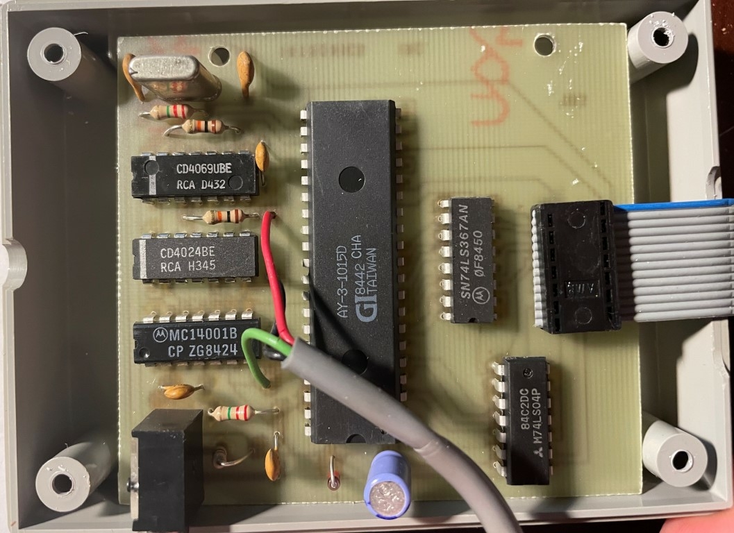
Check out the electrolytic cap at the bottom of the board. See where its positive side goes.
Funny story. Eons ago I designed a circuit to add a CR for every LF on a parallel interface. The circuit was built on a powered breadboard unit, and once while I was testing it I forgot to turn on the power. BUT THE CIRCUIT STILL WORKED! Blew me away at first until I realized that the circuit was getting power from the Data lines through the input clamping diodes of the CMOS IC's. Made for a really compact converter.
Is that a Grappler IIc box or similar?
I thought the Grappler IIc had a dip switch for settings...
If so, I think it is 9VDC power input.
I have a Hotlink (also Orange Micro) parallel interface box for the IIc and it is a similar form factor, however it gets its power from either the printer's centronics port or the serial port itself (there is 12V there on the signal lines) and has no power port.
It's not a Grappler, I mentioned in the first post it is a Kameleon by what appears to be a defunct company called Intronics out of Kansas. May have been a mom and pop type of operation considering whatever address Google thought they had at sometime is showing up as someone's house. There are no settings or dip switches
I traced out the positive side of the electrolytic cap, and it goes to several places, but namely pin 18 of the centronic connector . Which is a +5v/50ma pull up from what I found. So it does look like it can self power from the printer port. The ground seems to go to pins 16 and 29, which are logic ground and signal busy ground. The power Jack connects to the +5v line through a 220 ohm resistor.
I dug through some of my other Apple II stuff, and found the instructions for this in the back of my 5.25 disk caddy of all places (not sure why I didn't keep it with all my other manuals). And it does confirm that most printers will self power the converter, but some like Epsons may not. In those cases, you should use the included power adaptor (no power specs are given in the manual). Which since I did not see a wall wart in the box with this, I can only assume my old C.Itoh Prowriter Jr did power it. So I know it uses +5v. But I wonder if that 220 ohm resistor is there to drop what would have at the time been a much more common +9v wall wart?
But now the manual raises some questions about printing from ProDOS basic. A little while ago I noticed I was having trouble printing from ProDOS 2.4.2 with my IW2 and just doing a PR#1 and doing a list or whatever. I found that I had to override the bit setting to 8 using the ctrl-I commands after issuing a PR#1. If I used the last official version 2.0.3, I didn't have to. I could print directly without changing anything.
This manual indicates that the //c default ProDOS printer port settings were 9600 7n1. But I know the IW2 wants 9600 8n1. And I printed fine with 2.0.3 basic. So now I'm wondering if Apple originally set the port to 9600 7n1 in early 1.x ProDOS versions, but then changed to 8n1 in later versions. Then when ProDOS 2.4 was worked on, it got reverted to the original behavior of setting 7n1?
I would be surprised if that 220 Ohm was being used to drop 9V down to 5V. It is pretty small and I'd think might get pretty hot if it were used for that and the resistor doesn't show any signs of having had that happen. 6V DC wall warts weren't that uncommon back in the day either, and using a resistor to trim 6V to 5V would generate a lot less heat I'd think.
If you take a look at the bottom left of your picture, I do believe that there is a Voltage regulator like a 7805 (black heatsink attached?).
It's just an assumption because the picture doesn't show to much details.
So if you could do some pics of the bottom of the PCB as far as a pic of the black heatsink ? and it's regulator... could be of some help.
Update: as far as I can see... there isn't any power jack installed (as long as it's not the mysterious black box ?), just the serial and the parallel cable. If this black box is a power jack, then I do believe that you have to power the unit with +5V DC, because the shown ICs are all powered by 5V DC.
Datasheet of the shown AY3-1015 attached:
https://www.applefritter.com/files/2021/09/29/datasheet.pdf
The black thing near the bottom is the 3.5mm jack used for an external PSU, if needed. I know the circuit needs +5v, but I just didn't recall many 5v wall warts back in the early 80's. Seemed like they were all 9v. But they may have been other voltages as well. It looks like they may have expected slightly more than 5v, as the positive connection on the jack goes through a 220 ohm resistor before connecting to the +5v rail. The interface card is swappable on these Commodore printers, so i confirmed that pin 18 has continuity to the sole electrolytic cap on the interface card. So it seems like this printer should be able to power the Kameleon converter without a PSU.
I can post the solder side of the Kameleon if anyone is really interested in it. I'm going to go out on a limb and guess its a fairly generic conversion circuit, probably almost identical to other devices from the era. The only other thing slightly unique about this converter is they also included a ProDOS disk with some utilities for printing graphics files. You can invert them, zoom in on them, or just print a section of the full picture. I don't think it actually requires the Kameleon interface though, so maybe the software would be of interest to others? You do have to select the printer you are sing though, and it only lists a handful - Epson MX/FX, Gemini 10(x), Okidata 80/90, C. Itoh Prowriter, and Seikosha 550a/700A.
I did confirm though that it all works. Hooked it up to my //c and one of my "new" Commodore 1250 printers set to parallel/Epson FX mode. I broke into basic form the check disk screen after booting, did a PR#1 and the printer responded with a line feed. typed in some garbage at the prompt and everything echoed through the printer. Then I fired up Print Shop, set it up for an Epson FX printer and made a test sign. I apologize for the blasphemy of using a Commodore printer with an Apple going on here. If it makes anyone feel beter, its technically a Citizen 120D printer that Commodore rebadged.
IIc MPS1250.jpg
The print quality isn't as nice as my IW2. And seems to be dragging some ink across each line. The print head carrier probably needs to be cleaned. I really bought this to work with my C64 though, so no big deal that its not up to the IW2 standards.
Great that it works.
Anyhow, if you are requestet to use a PSU, the 220 Ohm resistor will not be stressed by this.
So my mother in law ran a ti-99/4a store back in the day and I found this kameleon parallel printer interface stuffed in the box. Since it was 5 pin, I always assumed it was some sort of screen grabber since on the 99, video and audio are 5 pin like the apple iic's serial port. I only recently got an apple ii of any kind. I found out that my wife had an apple iic around the same time their house was filled with amigas and ti-99s. I'm excited the mystery has been solved. I don't have any disks or the manual. Do you still have them?
Also not sure how to embed a picture but the power supply is in fact 9v with positive on the inside.
Here is the disk image that I made a couple years ago. I'll try and get the manual scanned in the next day or two. I thought I had scanned it back when I started this thread, but can't seem to find it if I did. I think I know where it is in my basement, just a matter of finding the time to scan it. As for the power supply, interesting that it only relied on a 220ohm resistor to drop from 9v to 5v. Given that linear power supplies drop differently depending on the amperage rating and actual load, I'm guessing the rating must have been small - maybe 250mA? Most parallel printers supplied a small amperage 5v signal on the interface, so a dedicated PSU was not required most of the time. I know my old Prowriter Jr did, we never used a PSU with our interface. Shame I can't get ribbons for that any more.
Glad to know this thread actually helped someone.
Actually it's 500mA. It is surprising though
I for the life of me can't lay my hands on the manual now. I had put all my Apple II related manuals in a single box a while back, and it isn't in there. Its also not in the box with the Kamelon. Nor is it with the disk. I spent over an hour looking for the thing tonight and can't find it. I just don't know where else I would have put it. I'll keep looking as time permits, but I'm not sure where it wound up. When I find it I'll be sure to send you a PM, so you'll get an email alert.
Thank you for tryin hopefully it will turn up
I was cleaning up my office over the long weekend, and lo and behold the manual was found mixed in a stack of non-Apple related papers. The scan is attached. I will send you a PM so it hopefully triggers an email alert to you, as it doesn't look like you are frequenting here.
https://www.applefritter.com/files/2025/05/30/Kameleon%20Apple%20IIc%20Parallel%20Interface.pdf
In post#10, 'nick3092' wrote:
" Shame I can't get ribbons for that any more. "
Uncle Bernie comments:
all you need is a depleted or 'dried out' ribbon cartridge for that printer, if it is a fabric ribbon.
These can be refurbished by using the same ink refill fluid they use for rubber stamps, but it must be applied sparingly. Back in the day (1980s) they sold little plastic gadgets with a hand crank - these would snap onto the printer cartridge and they had a small ink transfer roller (or a pair of them) and a built-in fluid tank you would fill, and then place the ribbon between the rollers and start cranking until the whole length of ribbon had new ink.
This was the 1980s version of the 1990's and 2000's DIY inkjet printer cartridge refills.
And these plastic gadgets were so cheaply made (same 'quality' as a kid's toy water pistol) that they produced an incredible mess. You had to wear disposable gloves and old rags and work on a place where the spilled ink would not matter (such as on the backyard lawn). But it worked - after a few printouts of black stripes the new ink had equalized and the printout had the same quality as with a factory fresh ribbons.
I think that such a refill device could be improvised with a few parts made from wood, nails and wine corks. The trick is not winding the ribbon but the dosage of the ink, but this could be done manually with a brush held against the transfer roller, and some patience.
- Uncle Bernie
Everything I've read about re-inking ribbons is mixed results at best. Not to mention eventually the ribbon will wear out from the pins striking it. And I thought most of these had some kind of foam pad inside that reinked the ribbon during its lifespan. If that sponge starts to wear out and tranfers to the ribbon, I could see that being a problem if it gets into the print head.
Funny you mention a board with some nails in it... I used a contraption based on that for re-inking DECWriter ribbons back in the day. Those weren't even a cartridge, they were just ribbon on two spools. I used if I remember right a mixtire of some of the cheapest pen ink from the university book store and some kind of light machine oil. Never had a problem with it because those ribbons were thick and those printers were absolutely built like tanks. Slow, noisy and huge, but I got them cheap from the university surplus store and they were wide carriage. I used to get boxfulls of massive printouts of wide carriage paper for free from where my Dad worked. They were printed on one side, usually with COBOL or FORTRAN program listings or data dumps or reports, etc. But the back side was clean.
In post16, 'nick3092' wrote:
" Everything I've read about re-inking ribbons is mixed results at best. "
" Not to mention eventually the ribbon will wear out from the pins striking it. "
Uncle Bernie comments:
What you can read in the internet about re-inking ribbons is irrelevant - you should try it yourself. There are plenty of morons out there who never read manuals (which came with these re-inking contraptions). And if you improvise a re-inker, well, then you need to experiment a bit and start with very little ink added.
True, the ribbon will wear out, but back in the day, I found that a fabric ribbon for a needle printer typically could be re-inked half a dozen times, and a ribbon for a typewheel printer could be re-inked maybe a dozen times before they were worn out.So these were substantial savings.
We should also keep in mind that this re-inking suggestion was meant to bring vintage printers back to life, so occasionally they could be demonstrated how it was (the noise, the oily smell, how the printout looked). It makes NO sense to have a vintage printer in the collection which does not work and cannot print anything. You would not use such a printer for daily printing in the home office, though. Use a modern laser printer instead.
On sponge pads in the cartridge:
If there is such a sponge pad in the cartridge, it may need replacement. But I never encountered a ribbon based printer cartridge which had an internal re-inking mechanism. Would make no sense (the manufacturer wants to sell you more of those expensive cartridges) and it probably would also leak and make a mess in too many cases, and customers would complain and sue for damages, like ruined office attire, ink stained office furniture, etc.But of course I can't rule out that such cartridges existed - there were countless models of printers and each had different cartridges, of course to rip off the buyers of these printers.
General advice on printer cartridges of any kind
Same foul game with the inkjet cartridges and now the laser cartridges - but at least for my laser printer, some company found out how to make clones of the proprietary chip inside these cartridges, so they can sell new cartridges at a reasonable price. With the moon prices for the original laser cartridges, it was probably cheaper to throw away the whole printer when run empty. The same bizarre situation occasionally existed with some inkjet printers - these were sold at a lower (discounted) price with a set of ink cartridges in the box, and a new set of ink cartridges did cost more than the whole printer with its initial cartridge set. So to the landfill it went. I'm very pragmatic about such ripoff schemes. Any "money sucking black hole" in my possession gets ruthlessly dumped into the trash can or sent to the junk yard.
- Uncle Bernie
It's a little off-topic but the printer to get these days if you can't afford the scratch for a color laser is the Epson Ecotank. Instead of ink cartridges it just uses ink from a bottle. And the ink is waaaaaay cheaper than the cartidges for other popular brands of printers like Canon, HP, Brother, etc. I was a fan of Canon for inkjets and Brother for lasers in the past but I got an Epson Ecotank a while back and I'm totally impressed. It was also the absolute easiest printer installation I've ever done. I plugged it into an Ubuntu Linux box, went to the printer control and it was detected and just worked including color printing, double sided printing and even scanning. I've never had anything go so smoothly on any platform before, possibly excepting a Mac with an Apple branded printer (go figure).