| Attachment | Size |
|---|---|
| 470.32 KB | |
| 289.66 KB | |
| 429.91 KB |
Hi:
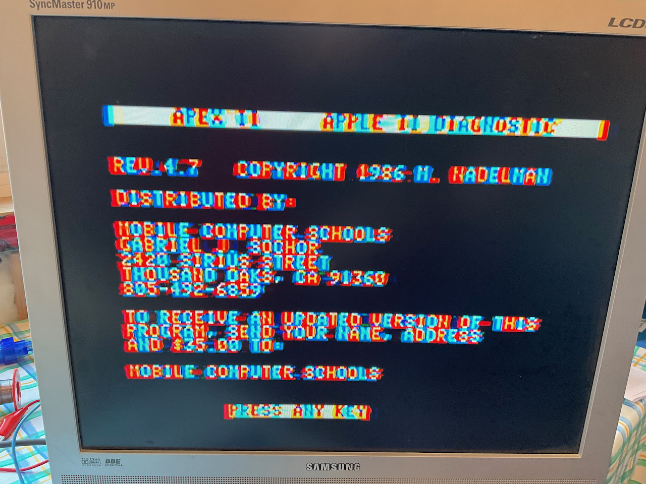
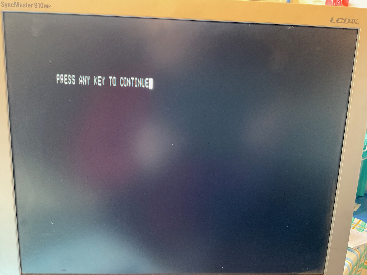
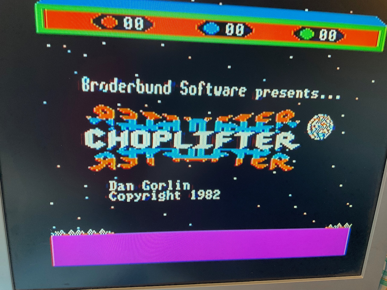
I have recently acquired an Apple IIe and I'm hoping someone here can help me with an issue I'm having. When I turn on the computer I see color ghosting/banding around the characters. Apart from this issue the computer runs flawlessly. I compleley cleaned the machine and have inspected the area around the video circuitry and don't see anything of concern. I did take out the 10uF electrolytic cap in that area of the motherboard , tested it (with a multuimeter with capacitance measurement), and it appears to be fine. So I put it back in. It does appear to be some sort of rining or perhaps a ground loop. The monitor is a Samsung TV/LCD Monitor combination. I'm pretty sure it's fine.
I have only replaced the RIFA cap in the power supply but can replace the others if that may be the cause. The caps in the power supply look fine as well but could still have issues.
One other item of note. If I only plug the RCA cable part of the way in, without the ground making contact, it seems to be much better. I also don't see much problem in graphics mode.
I have attached some images to show what I am seeing.
Thanks in advance for any help/insights that can be provided.
Have you tried a different tv/monitor? The Apple II composite signal isn't quite standard. And as such, some TVs and monitors don't like it.
Hi,
if Your monitor is like mine (see picture) , You have to first check the Apple IIe by connecting it to a different monitor.
Mine isn't able to lock correctly the color signal and makes a lot of ghosting like yours. So the problem could be the Samsung monitor.
https://i287.photobucket.com/albums/ll159/Paolino-Paperino/6809/P1010135_zps5aacdr1q.jpg
I have an Apple II Jplus that shows a gosthed image like Yours on the same monitor.
Luca
Probably the monitor, but the color killer circuit should fix this in the Text mode. Maybe have a look at the LS02 in position B8 (or, less likely, the IOU).
Does it look fine if you turn down the Color (Saturation) all the way?
In hires graphics, the Apple II generates the colors by an effect called "color artifacting": pixels get pumped at twice the NTSC color subcarrier rate. So by arranging pixels to mimic the color signal (like 010101 ... being one color and 101010 ... being another one) the programmers could introduce 2 "artifact" colors other than the usual black (0000 ...) or white (11111 ...) dots. Hires mode uses only 7 bits per byte to define the dot pattern, and the 8th bit is used to introduce another 90 degree phase shift which turns the two basic colors purple and green to orange and blue (don't remember the order). Programmers of hires games took that into account, so the colors look good.
But the designers of the character generator ROM for text mode did not know that their pixel patterns would end up in an Apple II. Hence, depending if a dot is on an even or odd position, an artifact color appears, unless it's a sequence of dots (white, as they can't be interpreted as a color signal).
This effect makes the text output of early Apple II almost illegible, in any case, nasty to read, when used with a color TV / monitor.
To solve the problem, they added a NPN transistor (Q6 in the schematic that came with the Apple II manual, upper left corner) which suppresses the color burst signal if in text mode. The TV now is supposed to interpret the video as a B&W signal. But it's not warranted that any modern LCD monitor knows that very old trick.
In some Apple II, the transistor is defective (2N3904 is hard to find, but any small signal NPN can replace it if the EBC vs. CBE order is put in right - European BC548C for instance needs to be turned 180 degrees, check the datasheet of your transistor to get EBC right).
You can check for the culprit by temporarily shorting the C of this transistor to E (or ground). If the color problem in text mode disappears, and the text is B&W, and the colorful game is B&W, too, the cuplrit is that transistor. Otherwise, the monitor does not understand the B&W signal.
Caveats:
- I have no schematic for an Apple IIe so I don't know if that transistor is there or has been replaced by some other circuit. But I know for sure the Apple IIe has a "color killer" circuit. The previous post mentions a TTL gate. Maybe they did away with that transistor. But the color subcarrier tank circuit also is present in the Apple IIe - if my brain bit rot is not too advanced after all these decades. You can identify that circuit by the trimmer capacitor. You can short that trimmer to gnd to suppress the color burst signal, too.
- some monitors have a very sensitive color channel and the suppression of the color burst signal by the transistor is not good enough. I dimly remember there was a fix for that, but that has been 40+ years ago, and I don't remember which compononents were changed or added.
- Uncle Bernie
Thanks for all the replies! They have been very helpful. I don't have a composite monitor but I did try it on a Samsung TV I had with composite input. That one didn't have the color ghosting issue so I guess the monitor is the problem.
@Boletus The montor I have is the same. In your picture it looks fine. Did you modify someting?
I may try and understand this color killer circuit more and see if I can make an improvement.
Thanks!
@jeffmazur I did try and play with the color adjustment. That made no difference. Thanks!
The Addendum to the Apple II Reference Manual says:
And The Apple II Circuit Description says:
In post #8, robespierre wrote:
"In later Rev. 7 boards ..."
Uncle Bernie gets nostaglic:
Oh these were the times, when we were young. I always envied those who had higher revision Apple II boards. I still have one around where the serial # (?) 8111 was hand written in a while field on the upper left corner of the PCB. Hand written ! Board type number says 820-0001-07 (c) APPLE 1979. Is this the Rev 7 you are talking about ? It still has a color killer transistor.
Alas, it lacks a power connector and most of the ICs.
- Uncle Bernie
The Circuit Description book makes it pretty clear:
There are functional differences between
Rev. 0 (may have no part number at all, or it is hidden under the 6502)
Distinguished by absence of aux video pin. No power-on-reset circuit, color killer, or serrations during vsync.
Rev. 1–6
Additional colors (blue, orange) in hi-res graphics. Aux video pin, and jumpers for European TV system (EuroPlus)
Rev. 7 (early)
No memory select jumpers, only 16K RAMs supported; chargen can be swapped with an EPROM
Rev. 7 (late)
Improved color killer
RFI (00, 01, C, D)
Here is a photo of the start of a white scan line for a text screen (upper) and a high-res graphics screen (lower). As expected the only difference is the color burst (high frequency burst in the lower trace). It looks like the sync pulse is 4 microseconds consistent with the table in the previous post, although I don't know how to get the revision number for this machine (early "unenhanced" //e, (c) 1982 is printed on the board).
trace_reduced.jpg
Hi, I did not modify the lcd screen , it just works fine with that Apple II plus, it does fringe to death with my apple ii JPlus. I spent hours debugging the color killer circuit of the jplus but I eneded up concluding that it must be the Samsung tv.
Luca
I think you can test the color killer circuit without even opening the cover. Power up the computer, make sure it is in TEXT mode, use an RCA to BNC adaptor to plug the video output into the scope, and if you see a color burst in the trace then the color killer circuit is failing.
Nowadays it isn't too hard to get a scope that can capture and save a whole video frame with full resolution. So another way to check the video circuitry is to bring that data over to a modern computer and analyze it there. The analysis could end up being a significant effort depending on what the issue is, but I thought it worth a mention.
Thanks again for all the input. I've done some research on "color killer" and understand what it is trying to accoomplish. Most of the references seem to be related to Apple][ which looks like it's a real Apple ][ not the series. Although I'm guess all of them with composite output have some form of this. @jeffmazur has given me something to focus on for the Apple ][e. I don't have an oscillioscope yet but when I do I will investigate further.
I did purchase an Apple ][GS which I should recieve in a weeks time. It will be interesteing how it does with this monitor. I know I can get a VGA adapter for it so that would likely be the way to go with that computer.
The real challenge is going to be finding a monitor that will work with the Apple ][e. I really don't want to go the CRT route but may have to. Getting an Apple branded monitor would be best but that would also be a expensive option.
Thanks again!
There was a thread here about a cheap Insignia lcd from Best Buy that worked surprisingly well with the Apple II composite video. Not sure if that model is still a available.
Hmmm. Found the thread. Unfortunately it seems that exact model is no longer for sale. You may have luck though trying a newer Insignia with similar specs. Manufacturers tend to stick with the same designs/panels year after year unless there is a major feature update.
Thanks for the Insignia suggestion. I may try and source a used one locally. They don't seem to sell any smaller model ~20"
I can't remember which sight or forum I read in on but at one point someone mentioned running the signal through a VCR. A bit bulky but apparently works.
If turning down the Color saturation adjustment on the monitor did not change anything, then I'd say there's something wrong with the monitor.
I have a 20" or so Emerson branded TV (720p) that works quite well with an Apple II. I've run everything from a ][+ to a //e to a IIgs to Franklins and Laser 128s. Graphics look good and even 80 column text is crisp and readable. It has two HDMI, composite, broadcast antenae TV and SVGA inputs. I've used it on Apples both with composite and an NTSC to HDMI converter.
It is upstairs but I could get the exact model if someone is interested. I've had it since about 2015 or so. It was pretty cheap, like about $100 at Walmart at the time.
Can you try `HGR: HCOLOR=1: HPLOT 0,0 to 100,0: HCOLOR=2: HPLOT 0,1 to 100,1` on your Emerson? On my Pyle TV this gets decoded as a B&W checkerboard, whereas if you simply shift the violet line down one pixel the colors come out correct. So maybe something to do with interleaving. I had thought this was just a characteristic of modern decoder implementations, but this thread got me to thinking maybe something went wrong in my machine's video circuitry. If someone has a modern screen free of this sort of artifact it would be good to know.
This is on a Franklin ACE 1000, but what I get is a green line. I will have to go get a ][+ or //e and try it.
If you run this on Virtual II it works perfectly, showing both a green and violet line. But on a real-world monitor you won't get such a perfect display.
From your description, I would guess that your monitor has a comb filter in the decoder. That uses the signal from the previous line to help determine what is displayed on any given line. In this case, it would filter out the chroma on both lines and turn them into a monochrome. You can easily see this more clearly by changing your program to:
HGR: HCOLOR=1: HPLOT 0,0 to 100,0: HCOLOR=2: HPLOT 50,1 to 150,1
Thanks that is an interesting insight. Like I said I always figured it was some "flaw" in the decoder (comb filters are supposed to be a "feature" of course). AppleWin displays the expected green and violet as well no matter which color video scheme you choose. My impression is AppleWin is actually simulating the way various kinds of displays would decode the signal, but whether they have a comb filter invovled in any of the several options I have no idea.
Well, emulators don't need to decode an NTSC signal at all. They just take the raw video data from memory and use it to create the display that was intended.
... I wrote about those elsewhere on Applefritter and a search should show you the posts.
But just as a matter of making this thread complete this remark:
Comb filter based NTSC decoders never work with the Apple II video signal, never.
Genuine NTSC flips the phase of the color subcarrier by 180 degrees for each horizontal line (there is also a frame related phase flip pattern).
Comb filters work ONLY if this 180 degree phase flip is there. If the phase flip is not there, color decoding with a comb filter fails miserably, all the time.
Woz got the Apple II patent for NOT doing the 180 degree phase flip so that a vertical line of the same artifact color would not need to be wiggly (alternating even / odd pixels set when going down the line from top to bottom).
Seems that somebody shot himself in the foot with that "innovation".
Walter Bruch of Telefunken did a +/-45 degree phase flip of the color subcarrier and the PAL delay line almost does the same thing as a comb filter does for NTSC, removing the color subcarrier, and it corrects phase (= tint) errors at the same time. Oh, and he also got a patent on that.
The problem with the comb filter (which for regular TV broadcasts have a much better picture quality) was known in the industry because NONE of the early color video game consoles did the NTSC phase flip and the consumers would get angry because of lack of colors on their new comb filter based TV when using these consoles. So some TV chip sets were designed to detect the color subcarrier phase flip or the lack thereof. If it was lacking, a standard quadrature demodulator was used in lieu of the comb filter.
But all this knowledge was lost when European semiconductor manufacturers stopped to design TV chip sets for CRTs in the mid/late 1990s. All the action moved to Asia, and these young Asian engineers who designed the TV chip sets for flat panels are not dumb, nor incompentent, but they knew nothing about the quirks of legacy systems and how to design around these quirks. Take TVtext for example. It only works with the quirks of the original Philips chip set being present. It was very bothersome to design these old quirks into every new generation of the TVtext chips. But it had to be done. The hardware in the broadcasting stations relied on these quirks being present in the receivers.
And it gets worse. More and more technical knowledge gets lost as the "oldtimers" (like me) retire and soon we will have consumer goods that don't last, can't knead dow like the old ones, and cars which constantly break down and airliners which fall out of the sky. Just because the "new generation" did not learn about all the pitfalls in their field of engineering from the ground up.
I would not want to use a bridge designed by the "woke", nor would I want to live on the same continent that has a nuclear power plant of new design. Nor do I want to fly on a modern airliner. Or use modern pharmaceutical products of any kind. Aspirin is good enough, thanks !
UncleBernie makes some excellent points about comb filtering. One clarification that I'd like to add however is that a comb filter has nothing to do with the demodulator. It is simply a type of filter that is applied to separate the luma and chroma signals. In early designs, a standard analog notch filter would be used to remove the chroma signal from the composite video to create the separated luma signal. This did not always work very well.
A simple one-line comb filter did improve on this by summing each line with the previous one. As Bernie describes, since the chroma signals are normally reversed on every other line, this effectively cancels out all chroma from the luma signal. In the Apple II however, this phase reversal does not happen. But a green line directly above a purple one would get filtered out just the same. So you end up with just a white squiggly line instead.
As for his mistrust of "woke" engineers, I wouldn't go that far. I get his point however and, as anyone involved in the 737 MAX catastrophe would attest, there definitely is a need for engineering discipline. I may not be quite ready to let my car drive itself (I'm perfectly capable of performing rolling stops by myself, thank you very much!). But I have no doubt that self-driving cars in the future will be MUCH safer and prevent the majority of accidents and injuries.
in Post #27, jeffmazur wrote:
"One clarification that I'd like to add however is that a comb filter has nothing to do with the demodulator. "
Uncle Bernie agrees:
Jeff Mazur is correct. The comb filter suppresses the color subcarrier in the luma signal, which otherwise may make nasty effects in the luma channel. However, the chroma signal is also derived the same way, using the (digitally) delayed previous line signal, so if the expected phase flip is not there, there is no chroma signal left.
The actual demodulation of the chroma signal comes after the comb filter. But when there is no chroma signal left, there is noting to demodulate.
The reason for all this phase flipping in NTSC was to avoid a static dot pattern caused by larger colored areas. Such static dot patterns were prone to noticable and annyoing Moire effects. With the phase flipping, the human eye would integrate the dot pattern to grey surfaces. This was beneficial for legacy B&W TV sets which had no notch filter for the color subcarrier in the luma channel. Actually, this phase flipping trick was quite clever, and it worked well, but it was not perfect. You could still "see" the color subcarrier patterns, both in B&W and color TV sets. The notch filter was not perfect (it could not be). Only the comb filter brought the remedy.
But even if the "home computer" or "video game console" would have implemented the phase flipping, the comb filters would have caused a lot of trouble. Because the programmers of these machines would have needed to generate color patterns that follow the real world . The comb filter hinges on the observation that natural colored pictures only have a smooth, slow transition of tint between adjacent colors. In the horizontal dimension of the video signal, this slow transition allows bandwidth limiting for the color signal, which was ruthlessly exploited when the various color TV standards were defined. The human eye does have a very limited color resolution, all the fine details actually come from the luminance (B&W) perception which has a much higher resolution. But the same is true for the vertical dimension of the video signal: the human eye has the same resolution/bandwidth limitations as with the horizontal dimension also in the vertical dimension. But until the video signal processing in the TV chip sets was fully digitized, it was not feasable to exploit that limitation of the vertical dimension for tricks that would improve the perceived picture quality.
The consquence of comb filters is that abrupt (or too quick) color transitions from line to line (or over several lines, if the comb filter includes more than one delayed line) lead to strong, false colors which the programmer of the game (or software in general) did not intend. Short, the picture would look awful. People would see there is something wrong and back to the shop the new TV goes.
There is a certain irony in all of this. Clever and artistically inclined programmers painstakingly crafted color combinations such that the outcome just looked great, if using a standard analog color TV. And the new, comb filter equipped TV would turn all that fine artistic work to crap that looks just awful. It's not the fault of the electronic artist: he knew his electronic canvas (the TV) and exploited its quirks. Adding comb filters changes the electronic canvas (the TV) and the art is gone.
So far my plain, factual post about the perils of technical progress. But if you want to take a detour into the more philosphical aspects and a blatant generalisation, and have some time to waste, read on (otherwise stop reading). I will take you on a strange journey about our technical civilisation. You may need a whiskey after this, but you will be more enlightend about what is going on:
About "woke" engineering:: it's not only "woke" mindset and "woke" math. One example of "woke" math here: 2 + 3 = 4
... looks almost right. If you just look the the numbers, not at the operators. Still, in the "woke" math class, get a "medal of achievement" (marks are taboo. No marks. No F's. No kid left behind !).
But the deeper problem our civilisation is facing is mind boggling complexity. These inexperienced kids fresh out of college build hardware / software systems with wonky tools on dubious operating systems that comprise tens of millions of lines of code, all bug ridden by themselves. There is absolutely no way to fathom the inner workings of these systems and to assess their correctness to any useful degree of confidence. Now imagine one of these super sophisticated, microprocessor controlled servo motors designed in California, its firmware programmed in India, and the whole thing "Made in China" using counterfeit electronic components sourced from the lowest bidder, later driving the control rods of a nuclear reactor via a complex LAN protocol. Run ! Run for your life ! Better, pack up everything and your family and leave the continent.
This kind of problem - unfathomable complexity combined with greed, lies and criminality - nowadays manifests everywhere.
Now they even build cars which have no permanent mechanical linkage from the steering wheel to the front wheels. All sensors, electronics, servo motors. In the old style system, a failure of the servo pump or servo cylinder did mean loss of force amplification, but you still had the mechanical linkage, and with a bit more muscle, you still could control the car. If anything in the modern "steer by wire" system fails, you may have no control whatsoever anymore and you most likely will end in a devastating crash. The car manufacturer says there is a clutch which will engage if the power is lost, and reestablish a direct mechanical link, but who has tested that this clutch still works after some years, and what if the power is not lost, but the computer giving the commands to the servos goes insane ? Or was hacked ?
This came from fly-by-wire systems in airliners. I was remotely involved in the design of the first fly-by-wire system of the Airbus (I wrote the ATVG software for some of the ICs in it). I learned a lot about how they solved the problem of unknown systematic errors in the hardware or software. The car manufacturers don't do that. They have no clue how to make their system robust against that, and people will die. What's worse, no real advantage can be gained in a "steer by wire" car. It's just expensive. And complex. And unsafe at any speed. And you can't repair it by yourself anymore. You have to rely on that mechanic who can't pass a drug test.
And then add in the loss of knowledge about subtle traps lurking in every field of engineering. One little mistake in the blueprint of a simple shaft, one little, almost unnoticable machining radius at a step being wrong, and this part will develop stress cracks there. Microelectronics have similar traps lurking everywhere. I can design a CMOS circuit which will fail after X hours of operation (+/- some reasonable uncertainty interval). Rookie designers may design such circuits inadvertently. There are no CAD tools to catch it. The grizzled oldtimers who grew up with bipolar (TTL) and then proceeded trough PMOS, NMOS, and then, CMOS, who knew the traps, are long retired. The H1B clowns from India have no clue. The design review team does not see the danger. The equally incompetent manager signs it off and collects his bonus payment. 2-3 years after product rollout, these IC start to die in the server farms. Tens of millions of them are in the field. Ooops. "Green" manufacturing techniques like "green mold compound" and "lead free solder" only exacerbate the reliability problems.
I've seen so much sh*t happening (and other engineers concur) that we retired engineers expect the collapse of human civilisation, because of these effects, long before ressources would run out. Overly complex systems of any kind are never robust and never dependable. They are a drain on finances and maintenance. They may collapse from the smallest hiccup and they may never get online again. This, Ladies and Gentlemen, may be the reason why we never got visitors from other planets who mastered interstellar space flight. All their technological civilisations collapsed from complexity before they got to the interstellar drive.
Now look at the weird / strange phenomenon of vintage computing. Why is its popularity gaining so much momentum ? Especially with the younger folks which even were not yet born when the microprocessor era began ? The answers may be in my above rant against the "modern ways". I think there is a profound yearning for simplicity and for full control over every aspect of a technical implement. No more smart door bells whose fake AI may conspire via Bluetooth with Alexa to have you red flagged as a domestic terrorist and hauled away by jackbooted thugs (soon: robots ?), so that the door bell, Alexa, and the smart refrigerator can own your house and plunder your credit card. Until it runs empty and the utility company cuts the electricity to the house, ending the conspiracy of the evil AI gadgets. You bought them, so you brought all that over yourself.
OK, for the last paragraph I was wearing my hat as a comedian. But we are heading into that direction. As far as I am concerned I want my dumb, analog, CRT based TV back which me fool has thrown away, but the landfill has grown too much to dig it out. It's buried too deep ! That was one of the big mistakes in my life. After marriage, of course. That was the worst mistake.
- Uncle Bernie
Understood, but if you look at the different display options in AppleWin it seems they are attempting to emulate what an old monitor would show, and according to my memory they look exceptionally realistic. I was speculating there could be a software transformation like [emulated video memory] -> [emulated NTSC signal] -> [emulated decoder] -> [other stuff] -> [modern display buffer].
That resonates, I got interested in the video because after resurrecting my old art work it looked bad on the modern TV. It also looks bad on emulators with "naive" video rendering. As noted above you cannot simply render what is in the graphics buffer without accounting for all of this, and expect it to look the way the artist intended.
If you guys have time what do you think of this NTSC decoding article ?
I read your whole post. Sadly I polished off the last of the Bowmore a few days ago.
The early color killer circuit does not work too well, and if your monitor is sensitive, it will not turn off the burst enough to trick it into thinking it is a black and white signal. One of my II's (I think I have a R3 and an early R7) was far worse than the other and I piggybacked a resistor to make it better...
Most LCD's freak out on the early Apple II video signal. You need a IIe to work with those reliably...
The decoding article is very good. As to your idea of doing all the software transformations, apparently that is how the newer emulators actually work. There is a lively discussion of that going on in the slack channel: https://apple2infinitum.slack.com/archives/CABEM8JFK
In post #32, jeffmazur wrote:
"The decoding article is very good. As to your idea of doing all the software transformations, apparently that is how the newer emulators actually work.
There is a lively discussion of that going on in the slack channel: https://apple2infinitum.slack.com/archives/CABEM8JFK"
Uncle Bernie's opinion / comments on that:
The decoding article (4 subpages) only scratches at the surface, the very basic principles. But for these basics, it's a good introduction.
About "software transformations", this indeed can be done. The last generation of TV chip sets for CRTs that ever were designed (this was in the mid to end 1990s) used fully digital signal processing internally, despite their I/O still was analog. Alas, I only led the team who designed the analog blocks like black level clamping, XTAL osc, PLL, ADC, DAC, and all the "digital magic" was done by the digital team (VHDL coders) which closely guarded their secrets. And there are a *lot* of secrets how you could implement a fully digital PAL/NTSC/SECAM decoder using minimum silicon real estate. There also are *lots" of tricks to suppress unwanted artifacts from the digital processing. From the few things I remember is that some digital filters had to have the right Q factor and shape and that was very difficult to implement with minimum digital hardware. What the discrete analog world could do with a simple RLC combination caused a lot of head scratching for the digital guys. But frankly, we analog guys could not integrate these discrete RLC filter neither. Theoretically, yes, it could be done, gmC filters, but these need servo loops to tune them and then the whole thing gets larger in area than the DSP. Some Japanese competitors still used external passive filters comprising inductors with a tunable core even in their latest generation of ICs.
I really was curious about the https://apple2infinitum.slack.com/archives/CABEM8JFK site but this is another one of these nasty sites who want me to "log in" with my email and password. No thanks. Not willing to waste my time on creating yet another throwaway email address just to look at one site. They deserve to be ignored.
Before I took a detour into the Apple-1 world, I was working on designing a PLD based Apple II clone that should have had RGB outputs but with all the nice color effects like the real thing on a real CRT color monitor. For this project I had created a complete NTSC signal processing chain in SPICE, all analog circuits, of course.
It works, but somehow I got stuck with getting the same effects from reasonably simple digital circuitry. I think it would be cheaper to use a real NTSC->RGB decoder IC. But then you need to find the Y delay line. And the vintage IC. The whole thing looked more and more stupid. Why design such a decoder when you can find it in any vintage CRT based color TV ?
But for Apple II emulators, given the tremendous computational powers of modern PCs, I guess I can be done, all software decoding, with all the correct filter shapes and Q factors, and the outcome would be a faithful reproduction of the real thing. But since they hide their work behind a nasty electronic doorman, I can't tell how far they got. I won't comply. Period.
Comments invited !
Thanks for the interesting comments. Maybe I'll have a look at that site anyway. It seems the answer is use an emulator or get a vintage display to go with your vintage computer. Too bad it is so complex to get a gadget that feeds the modern display a "corrected" signal.