
Hello everyone,
So, since I started this project. I have been also thinking about doing another Apple-1 project. I still really want to make the most accurate Apple-1 Replica possible, and I have been looking at all the replicas that have already been done. There's currently the Mimeo-1, Newton-1, Newton-NTI, my version of the Russian Apple-1 Replica, the Justin McDermid version of the Russian Apple-1, & the original Misha Russian Apple-1 Replica. But after looking very closely at each of these replicas, I noticed that there are only (2) Replica boards that look remotely CLOSE to the original Apple-1, (At least cosmetically), those boards are, the Newton-1, & the Newton-NTI.
Now, after looking very up close at all the boards, I noticed something about the dimensions of the boards and the mounting holes. Here are the dimensions of each of the replicas:
Mimeo-1: 9x15.5 Inches
Newton-1: 9 & 3/16th inches X 15 & 9/16th inches
Newton-NTI: 9 & 3/16th inches X 15 & 9/16th inches
Misha Russian Apple-1: 9x15.5 Inches
My version of the Russian Apple-1: 9x15.5 Inches
Justin Mcdermids version of the Russian Apple-1: 9x15.5 Inches
So, I'm wondering what the ACTUAL official dimensions are of the REAL Apple-1 board, if there are any REAL Apple-1 owners out there that are willing to share the dimensions of their boards, that would sincerely help us out. Also, I am wondering why the Newton boards have different dimensions than all the other boards on the market. I tried to get in touch with Mike about why his boards are a different dimension, but he never really got back to me. Maybe someone knows why? Anyways, my point being that I am thinking about doing modifications to the Newton replicas because I think, using the Newton boards would make a GREAT use as a base blueprint. I am fully convinced that the Newton boards would allow me to make a highly better Apple-1 replica.
Comments invited!
Best,
Logan
In post #1, Logan wrote:
"So, I'm wondering what the ACTUAL official dimensions are of the REAL Apple-1 board ... ?"
Uncle Bernie answers:
I've noticed the discrepancies with the PCB board sizes from the different purveyors since the beginning of my strange journey into the Apple-1 world , but nobody seemed to care (the difference is too small to see with the naked eye, you need a ruler to find out). The whole thing became an issue only when Armin of Germany started to sell his pre-drilled plexiglass panels.
Since I have good connections to owners of Apple-1 originals, I can confirm that 9" x 15.5" is what the originals apparently had, on the left and top edge (A-1 in the lower left corner) but there are small differences in the order of 0.1" or less between different specimen. If these differences are due to measurement errors by the owners or due to manufacturing tolerances back in the 1970s, or shrinkage of the PCBs due to age, I don't know. But my money is on 9" x 15.5" because PCB layouters back in the day would have preferred to work with 0.25" increments unless some other criteria would have dictated to use some crooked numbers. The famous Eurocards according to DIN 41494 for instance are 100 mm x 160 mm and this has lured some American companies into making 4" x 6.25" PCBs which is not quite right and won't fit properly into an Eurocard card cage. The correct size would be 3.94" x 6.3" and here you have an example what can happen when converting between metric and imperial measurement systems. Oh, early steam boilers and engines used "stones per square foot" as a measure of pressure. Funny fact !
Comments invited !
Bernie,
Thanks for sharing that info about your experiences with the Replicas. I don't think your measurements of the REAL Apple-1 are inaccurate, but I would also like to confirm those dimensions with another Applefritter Apple-1 enthusiast as well. Maybe @macnoyd might know?
Best,
Logan
So, I have a little update here:
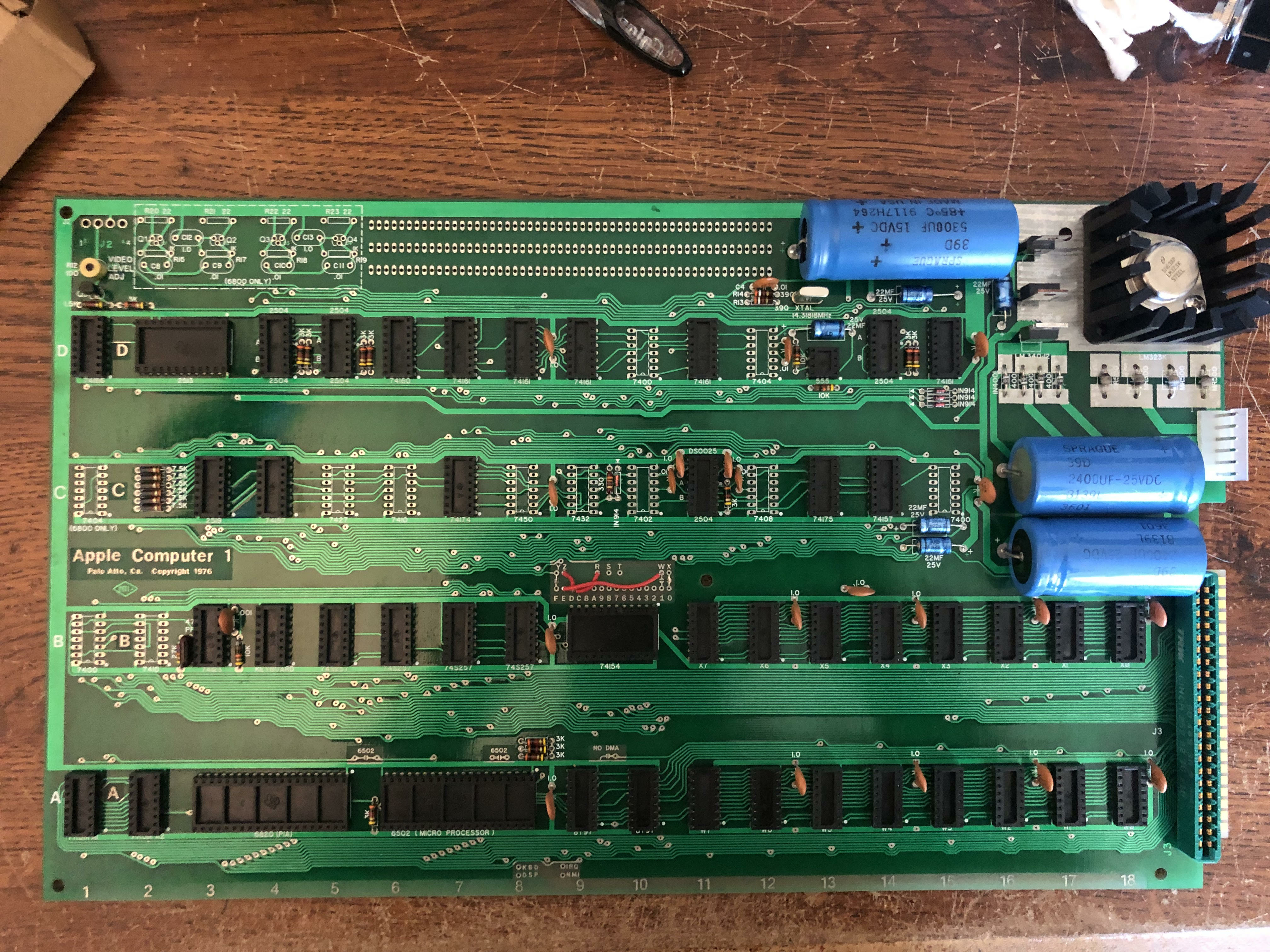
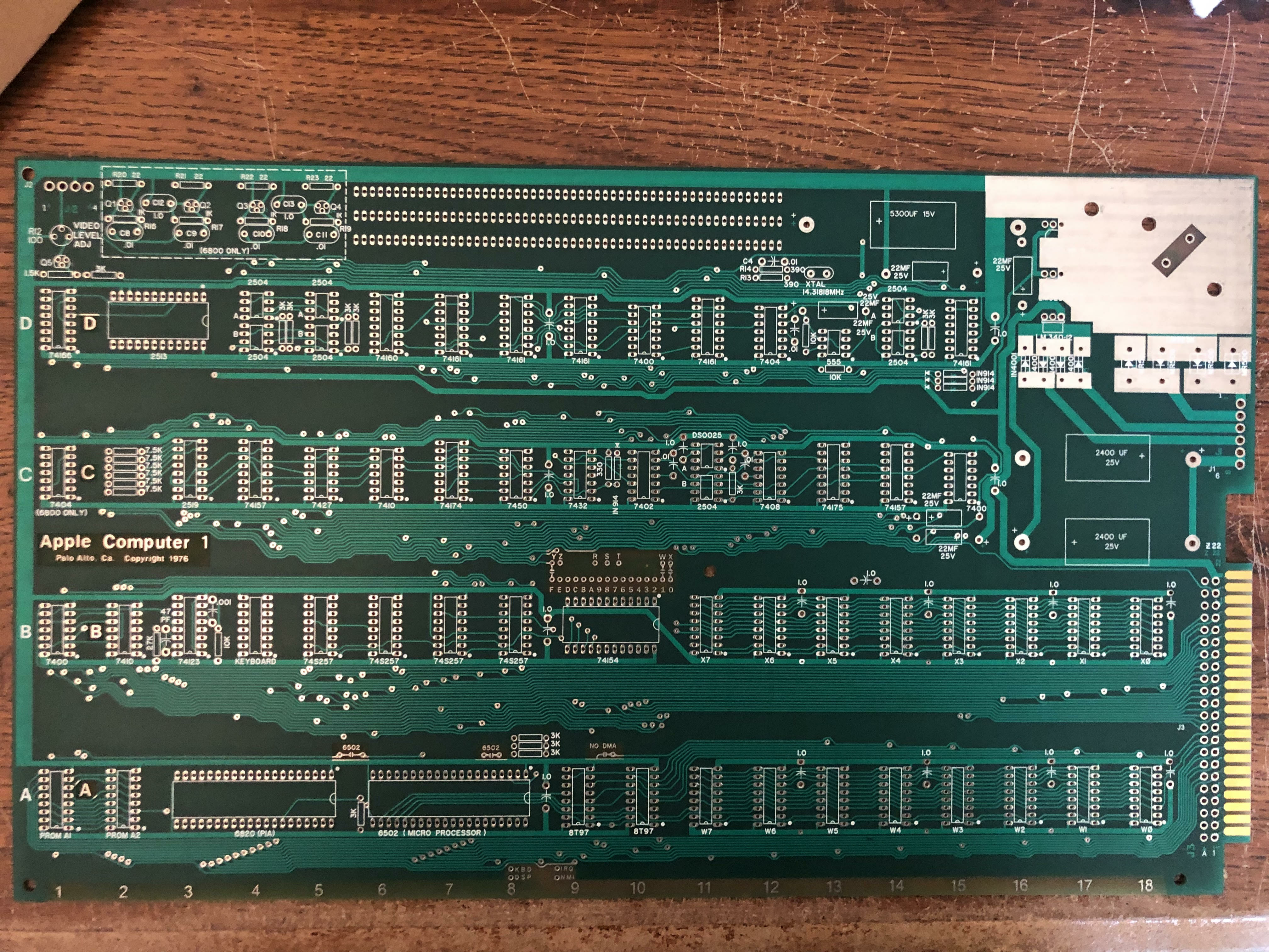
I’ve been working on making a PROPER Apple-1 replica for about a month, and it has been going VERY well. I found a 98% dang near perfect, top and bottom scan of a REAL Apple-1, and then I’ve been working in Photoshop and Microsoft paint to make all the little traces and adjustments…
The white photo is how it’s looking right now, the second photo is the original.
Here’s also a google drive Link:
https://drive.google.com/drive/folders/1-I96eYH3d1EjUZC3bmfCOlpTNxTng1Tr
Personally, I think I did fantastic work making the traces underneath the 74154 and the Sprague caps. It was really luck and guesswork that made that happen. All of this fantastic work is literally from reference photos, schematics, luck, and head banging. Seriously, it’s for sure a PITA, but it’s a PITA with love. LOL
P.S, The photo still needs some more editing, but it’s VERY close to being finished, as far as the top copper layer goes…
There was also an old documentary I was watching, it was from 1969 and from Techtronix, and they were discussing how PCBs were made back then, and it was so COOL seeing the literal traces each being hand down with graphical tape being applied to a grid paper. They happened to state that when this graphic process is initiated, the size of the completed artwork is 4x the actual expected board size. Then they resize it down to the actual size.
I had this idea for the Apple-1 too. Because if I also made a really large version of the board, it would allow me to make it in great detail, and I could probably resize it too, and possibly make positives and negatives and then maybe one day scan them digitally, or maybe even etch a board by hand. This is exciting!!
Comments invited!
Best,
Logan
In post #4, Logan wrote:
"traces each being hand down with graphical tape being applied to a grid paper. "
"I could probably resize it too, and possibly make positives and negatives and then maybe one day scan them digitally, or maybe even etch a board by hand."
Uncle Bernie's comment:
As a retired electronics engineer who has been there when the old "hand layout" process still was used, let me give you some advice, Logan:
- the "grid paper" was no "paper", it was a matte mylar foil which kept true the size and did not shrink or expand like paper does when the air humidity changes. This mylar foil was available with a raster corresponding to scale 1:1, 1:2, 1:4 and it was the exact same grid as the IC pins would have. There were self adhesive stickers with IC footprints and you could choose the form and size of the pads. Traces were done with self adhesive tape of different widths which came off spools. You could bend them as needed - this explains the irregularities of the bends in the traces. Larger copper areas were difficult to make. You had to cut them out from a special opaque foil using a small x-acto knife and then they were glued to the mylar foil.
- to save money you could make three foils: the foil with the pads, and then two foils for top and bottom traces / copper area. The traces were done on a mylar foil that was glued over the pads foil.
- when the layout was done, the mylar foils were put on the light table of a repro camera which was used to take the composite picture of pad foil / top foil and pad foil / bottom foil. These were not reduced in scale at first. Because they had to close all "holes" in the pads using black ink. There were special pens for that - not unlike the car paint touchup pens of today. When it was done, the photographic reduction to 1:1 was done. Reason is, there cannot be a "hole" in a pad of any film used in the process. The through holes connection happens because of the holes drilled, and not because of a "hole" in a film.
- The solder mask film was created by using the "pads" foil and setting the focus of the repro camera to be slightly out of focus, blurring here hereby expanding the pads but keeping their shape. This solder mask film was used to make a silk screen for both the bottom and top sides of the PCB to print the solder mask. On the Apple-1, two masks would be needed because of the cutouts, but this is easily done with retouching the master films, or you could even put black electrical tape on it (cutouts don't need high precision).
- The drill data tape (a real punched paper tape) was done with taking the "pads" foil to a X Y digitizer table. Each hole had to be targeted in crosshairs and then clicked. The layouter had to specify which diameter to use for every drill. This data tape was the only "digital" data ever used in the process.
Hope you see the problem now. You first need to find a local PCB company which still has the ancient equipment (repro camera, the dark room to develop the films, the manual digitizer) in good functional condition. And they still need the old guys who knew how to operate these and how to work around the quirks of the equipment. These people now all are retired or 6 feet under.
Oh, and the process is very time consuming, and hence, expensive. Making the exposure films and the drill tape for a PCB like the Apple-1 motherboard could cost thousands of dollars. Early 1970's dollars, mind you, not the nearly worthless GTP (green toilet paper) we have today. For the two Steves, the costs for making the first batch of PCBs was the main obstacle.
In the end, the problem you will run into is that nobody has the ancient equipment anymore, and the know-how is lost.
Nowadays, half a century later, everything is done with CAD and all the production machinery takes Gerbers.
So here is my opinion: trying to do your project in the "old way" is practically infeasable. But what you could do is to take one of the open source PCB layout programs and teach it how to use free form traces in a convenient way. The modern Gerber formats support all strokes and curves to make arbitrary shapes of everything. So you could mimic the "hand gluing process" of the past in the CAD program. I have experimented a bit with that myself and found it very tedius because the tool always tries to "help you" and makes your wiggly traces neat, straight, and clean, and on a raster. This is a feature that has been coded into the software. Remove that feature, use a super fine raster, and you should be able to draw crooked and wiggly traces with ease. Since you still have a valid CAD database, you can easily export Gerbers and have the PCB manufactured cheaply. And it sure would be awesome and people would think you found a stash of original, unpopulated Apple-1 PCBs in some warehouse. Oh, and let go any hopes to make plated through-hole PCBs in your garage. I am aware that some companies sell the process chemicals to unsuspecting hobbyists but unless it's a very simple, small PCBs the attempt will most likely fail (don't ask how I know ... these scams were around even 20, 30, 40 years ago. "Make your own double sided plated-through PCBs at home. Complete chemicals kit only $50". Yeah, sure. Sounds better than to pay $500 to a local PCB company to make you the one prototype you need. But it never worked in any satisfactory way.)
Just my 10 cent of advice ("use the right tools for the job at hand").
- Uncle Bernie
Uncle Bernie,
Been super busy with VCF East stuff, but finally getting caught up on AppleFritter.
You post is great but you missed one big thing. Back in the day the traces on the boards were also completely silvered over and then the green coat was hand screened onto the board. Today only the exposed traces are silvered and the green coat is applied completely different. Hand screened green coat was an art not a science. Using a binocular/trinocular microscope, I can tell you which Apple-1 boards were created by the same guy at NTI based simply on where his hand moved in the screening process.
Mike Ng "Newton", tried to reproduce the process where the PCB traces are completely silvered over before applying the greencoat so that he can reproduce the bubbling effect that wave soldering causes on the back of the PCB. It was a complete failure and the green coat peeled off in a non-authentic way. He sent me pictures of the attempts. The chemicals they used back then just aren't available and the magic formulas to match what was done back then are as you say 6 feet under.
Cheers,
Corey
In post #6, Corey986 wrote:
"Back in the day the traces on the boards were also completely silvered over and then the green coat was hand screened onto the board. Today only the exposed traces are silvered and the green coat is applied completely different."
Uncle Bernie answers:
Oh, I did not "miss" this small detail, as I've been there and had my PCB production runs made by those outfits back in the day. I glued my own layouts together on that mylar foil because there were no CAD tools. So I even know the tricks they used with the repro camera to produce the different exposure masks. Oh, and I saw how they silk screened the solder mask goop on. Not only this step was an art done manually but the drying process afterwards also was tricky. If something was done wrong the solder mask would wrinkle or crack (or fall off) as in Mike Ng's failed attempts. This art is lost. And also a reason why you don't need to fear "perfectly fake" Apple-1 forgeries. Unless somebody finds the mythical stash of original, unpopulated Apple-1 circuit boards under the cobwebs in some dusty warehouse owned by Apple (the Corporation) ;-)
I just did not mention this detail in this thread because I don't deem it necessary to make good, museum grade, replications of the original Apple-1. The straight, perfect traces and all the bends in the traces all being alike is a dead giveaway everybody who is willing to see it can see, even if the old museum trick of using dim lights is used. The modern vector fonts for all the lettering also are wrong as they are not the same thing as the rub-on letter sets we had back in the day to put text on these mylar foils.
As for the solder mask, Mike Ng had very good success with what is known as the "Newton non-NTI" PCBs: they looked duller (not glossy), and were of a darker tint of green. I've built one Apple-1 clone for my own collection using one of my early kits with the fat dark brown disc bypass capacitors and so far everybody who has seen it thinks it's an original. The 1404/2513/2519 PMOS chip set is from Signetics in the grey package and these have 1975 or 1976 date codes. Most of the TTL also are right vintage and manufacturer, but not a perfect match. But that is not necessary for the "first impression". Like any professional forger (or museum curator) you need to have a profound understanding on how human perception works and then tailor your piece of forgery to trigger the right reaction in that perceptron neural network between the ears of the victims. Bingo, everybody thinks it's an original. Stage magicians use similar tricks based on even deeper understanding of human perception. As long as it's not used for crime it's a really welcome craft of illusions. Our lives would be very dull and boring without these skilled artisans ...
A bit more about human perception and the greed / reward mechanisms which drive "clones" / "replicas" and "forgeries":
There are several Apple-1 clones built with my early kits in museums around the world and so far the visitors did not complain, I was told by the proud builders. My mission is to give builders the means to build illusions which are close enough to the priceless originals to fool the typical visitor, but no attempt is made to fool the experts like you, Corey. As I have explained in several posts in several threads here, it's impossible to build a 100% perfectly forged Apple-1 clone which would pass closer scrutiny of experts. Which has to be properly paid for to do a pre-buy inspection. Those buyers who skimp on that do so at their own peril. And, of course, the greedy gold-digger type bastards who fall for hoaxes also deserve to get fooled / scammed.
There was this viral video with the cardboard box in the warehouse and in the box there was an Apple II motherboard (in ESD bag) and another one ... an Apple I ... also in an ESD bag and only briefly pulled out and put back as "worthless". A lot of people fell for that hoax and called in from all over the world, harmlessly asking if that box with its "worthless" contents still was there ... they would fly in and buy it for cheap ... at least this is what I was told. Greed ! Plain greed !
The Apple-1 clone in that video was built with one of my kits, BTW. So the kits are good enough, I think.
I'm just waiting for little old ladies on Silicon Valley electronic flea markets to sell dusty and artificially aged Apple-1 clones (presented among other 1970s electronic junk) to greedy buyers. "Yes, Sir, my late husband had that stored in the attic ... I don't know what it is ... but he told me he paid $666.66 for that thing here, 1970s dollars, mind you, so if you give me a grand, it's yours ..." HarHarHar !
I saw this type of shenanigans a lot in flea markets where they sold "antiques" and similar stuff. The "antiques" of course had been pulled out of dumpsters in wealthy neighborhoods or were sourced from the mafia style "estate cleaners" who prey on widows and the heirs of deceased people who hoarded stuff all their life and now the house needs to get cleaned out ASAP to be sold ... the heirs see the quick $$$$ in the sale of the house and not the - sometimes immense - values in the antiques within. Most are worthless, of course. Those end up on the flea markets, waiting for greedy, gold-digger type buyers. The reason is that most of the desirable objects (artisan glassware, designer furniture, designer lamps, ...) were prohibitively expensive even when still being sold new, so a whole cottage industry sprang up to make ... clones / forgeries ! ... of these desirable objects for those who could not afford the Bauhaus originals or the like. The quality of these forgeries / clones of course varies greatly.
All these shenanigans and swindles are quite common and existed for ages. Why should "vintage electronics" be different ? As long as the object is rare enough and desirable enough for enough people, there will be scams. And the greedy will get scammed. The smart ones will consult the experts and pay for their authentication work. Same as it ever was, with every sort of collectible artifact ever devised by human civilisations.
Comments invited !
Can I ask to see a picture of your best Mewton non-NTI assembly? I managed to assemble almost all the components for my "dream replica" except for 2 open ic sockets TI 40 pin and small green capacitors, but now everything has changed, American stores are closed for me for a long time...
In post #8, macintosh_nik wrote:
"Can I ask to see a picture of your best Newton non-NTI assembly ?"
Uncle Bernie answers:
yes, I can send you one in a PM. Will take a few days, I'm very busy. But you probably will be disappointed: I use the modern machined sockets and not the "original" TI sockets which were used in the originals but are unreliable junk. For me, reliability is more important than the "right" sockets. The rest is as close as it gets and whenever I can find a TTL that is closer to the originals I do the swap, so my build gets better over time. No ceramic 6820 and 6502 yet, though. I do not want to pay usurious prices for them and rather wait for an opportunity where I can produce a few myself (transfer of die to salvaged white ceramic packages). We have a company here in Colorado Springs which does this transfer regularily. The trick is finding the "donor" ICs with the right vintage ceramic packages.
The point I want to make here with telling you about the "wrong" sockets in this open forum is to amplify my above statements about human perception: nobody ever noticed the "wrong" sockets. Nobody. Not one person. The fat dark brown capacitors, the vintage carbon composition resistors, the dull / dark green PCB, and the vintage ICs (not all of them !) trigger the perceptron between the ears and once the neural net recognizes the general pattern for an "original Apple-1" the observer is willing to accept this as a fact and it would require a lot of effort to convince him/her otherwise. This is the same psychological mechanism why most people, once they have swallowed a propaganda lie and "accepted" it as the "truth", will fiercely defend the lie against any evidence to the contrary. The human brain / perception is far from being perfect (and these quirks can be exploited both for fun, and for entertainment, and for fraud and crime, up to industrial scale mass murder).
I prefer to use my (limited) understanding of human perception and how it can be deceived to make nice kits for Apple-1 using just the necessary set of vintage components to make them look close enough like the originals so builders can have fun with them, at a still reasonable price. No way to fool experts, though. For a lot of money more I probably could make 99% perfect clones with all re-stamped ICs and the "real wiggly trace" PCB but for what purpose ? My current kits are good enough for museum grade builds. Furthermore, the missing 1% of clues I cannot possibly replicate are enough for an expert to reveal the forgery.
Getting "closer" to the originals is a pursuit which some builders spend a lot of time and money on, but IMHO it's not worth the added expense nor the added efforts, i.e. the 6820 and 6502 with the right ceramic packages alone will set you back by $600-$1000. If you can find them.
But maybe treating the Apple-1 build as a sort of "stamp collecting album" with the ICs being the "postage stamps" is a new hobby. Many a heir of a huge stamp collection allegedly worth six figures or more have found out nobody buys them and the stamp dealers only offer a pittance. Beanie Babies anyone ?
So my best advice for Apple-1 builders is to not over spend on expensive and rare parts. Other than buying my kits, which I think are a good compromise in terms of "correct" looks for the price, make sure that you at least get carbon composition resistors. I have found that their 1960's "looks" contribute greatly to the success of the illusion. Use modern resistors and - poof ! - the illusion vanishes. A few further "weird" looking parts like the glass bead rectifier diodes also can contribute to the right effect. Using the right PCB also is important. Logan's work "massaging" the Open Source Gerbers towards more authentic looks is promising, but so far I can't comment on them as my sample is still in the mail.
Comments invited !