
Hello,
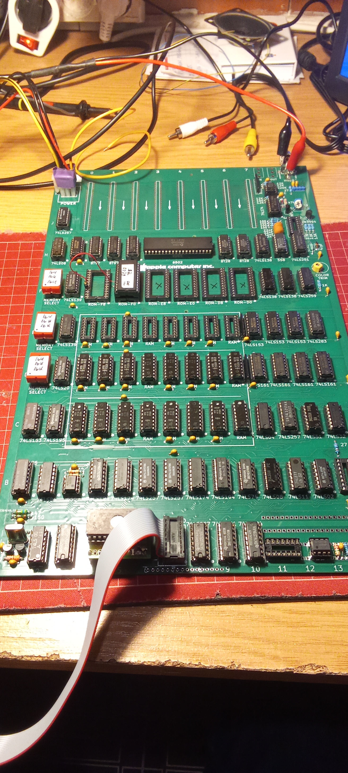
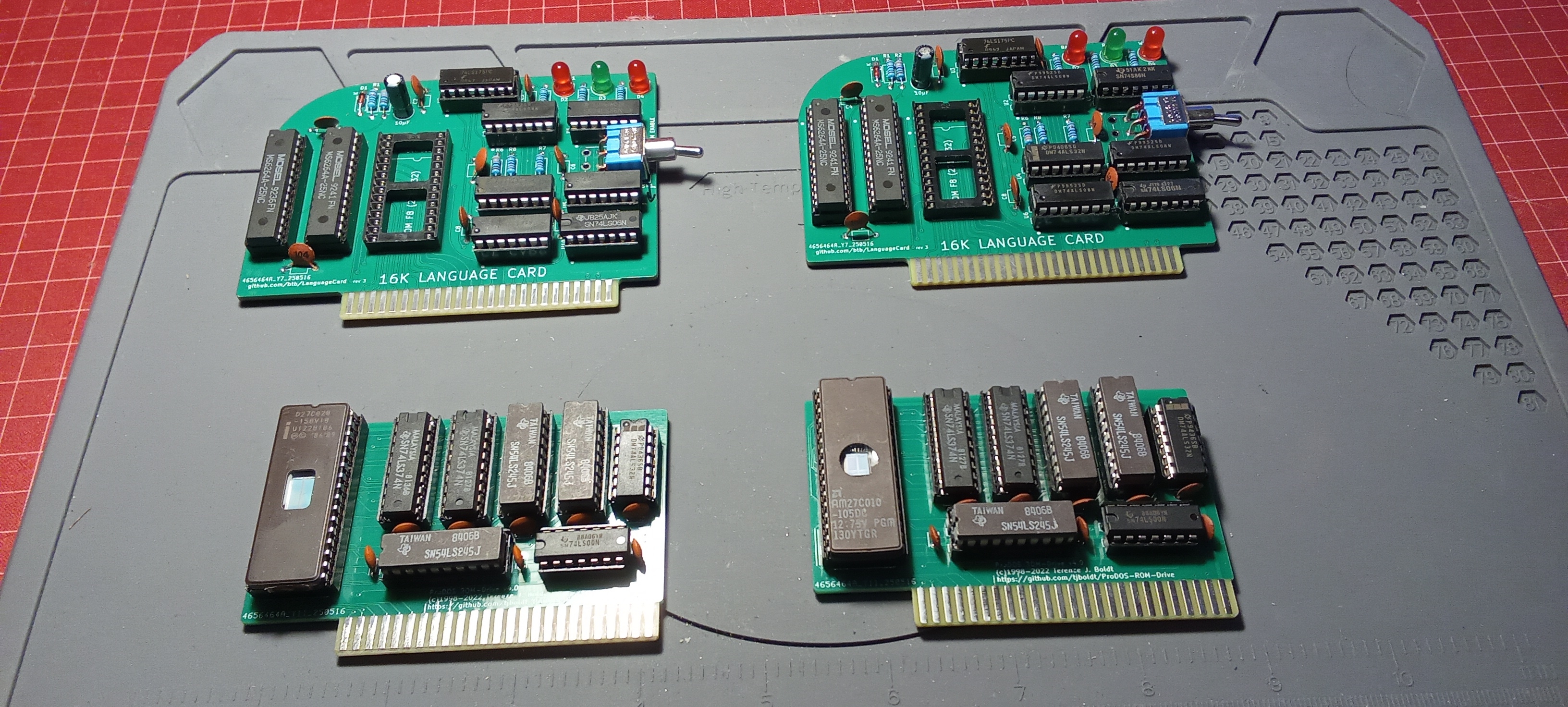
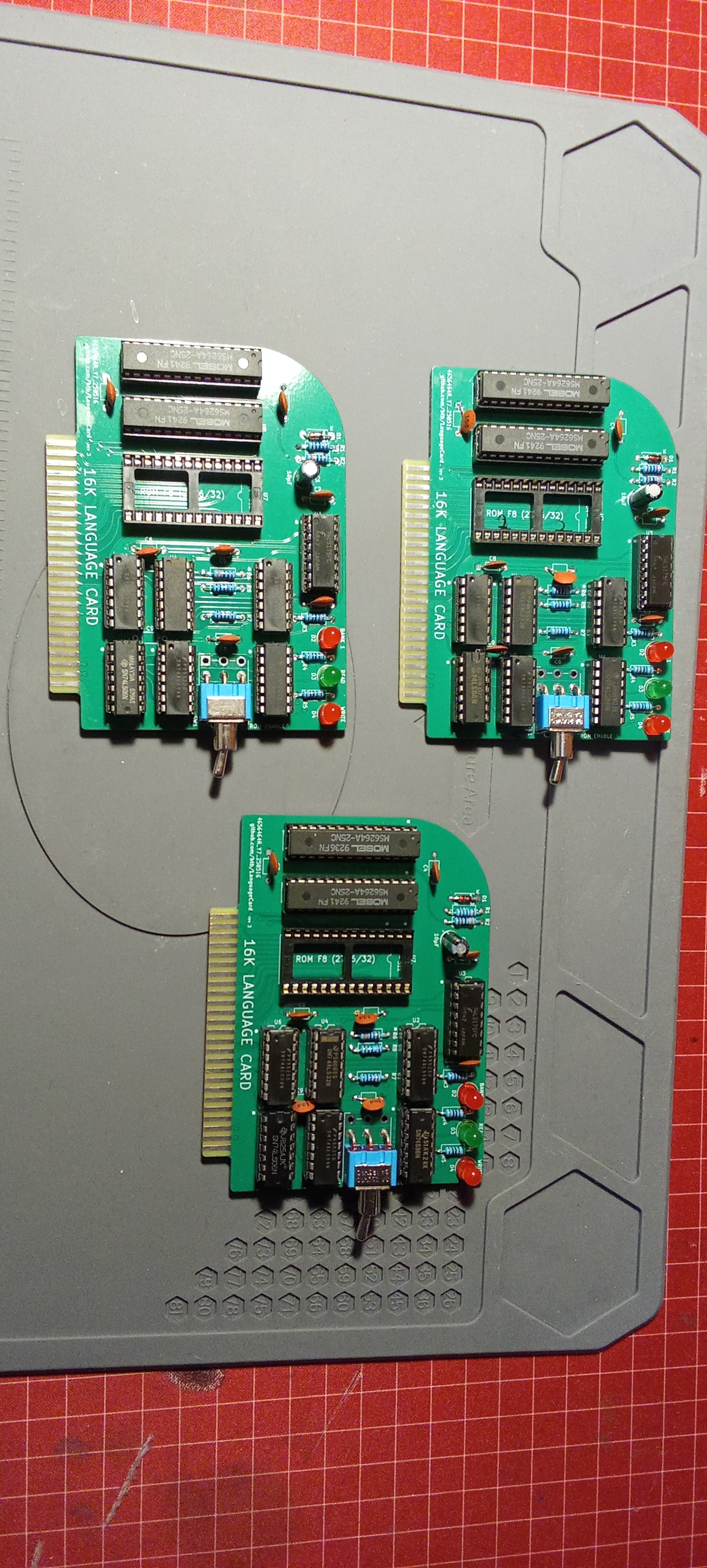
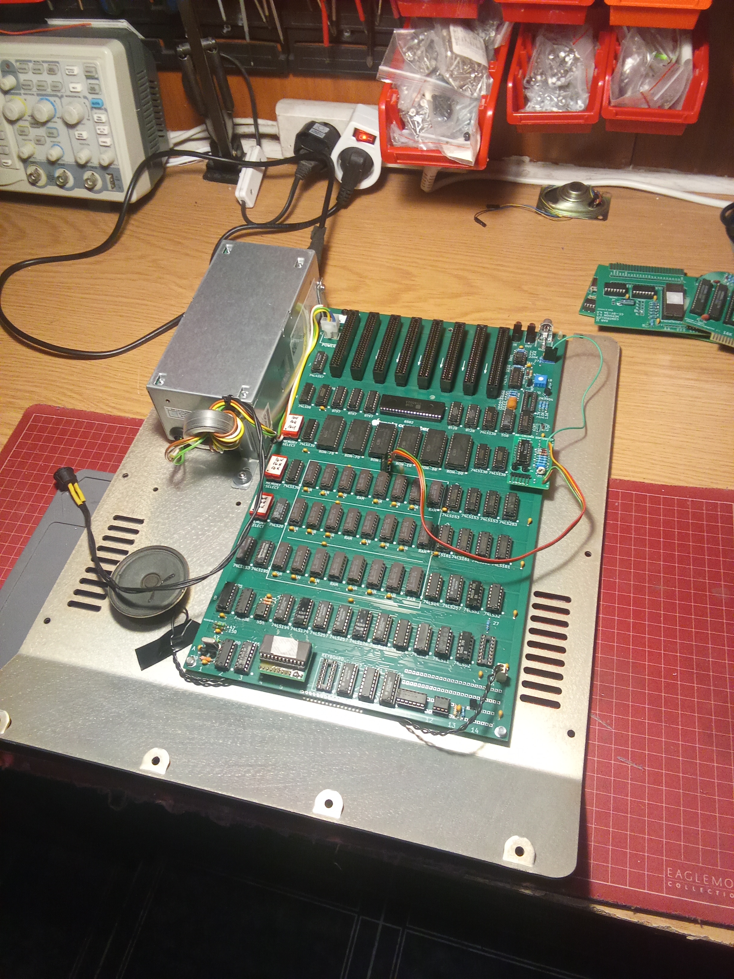
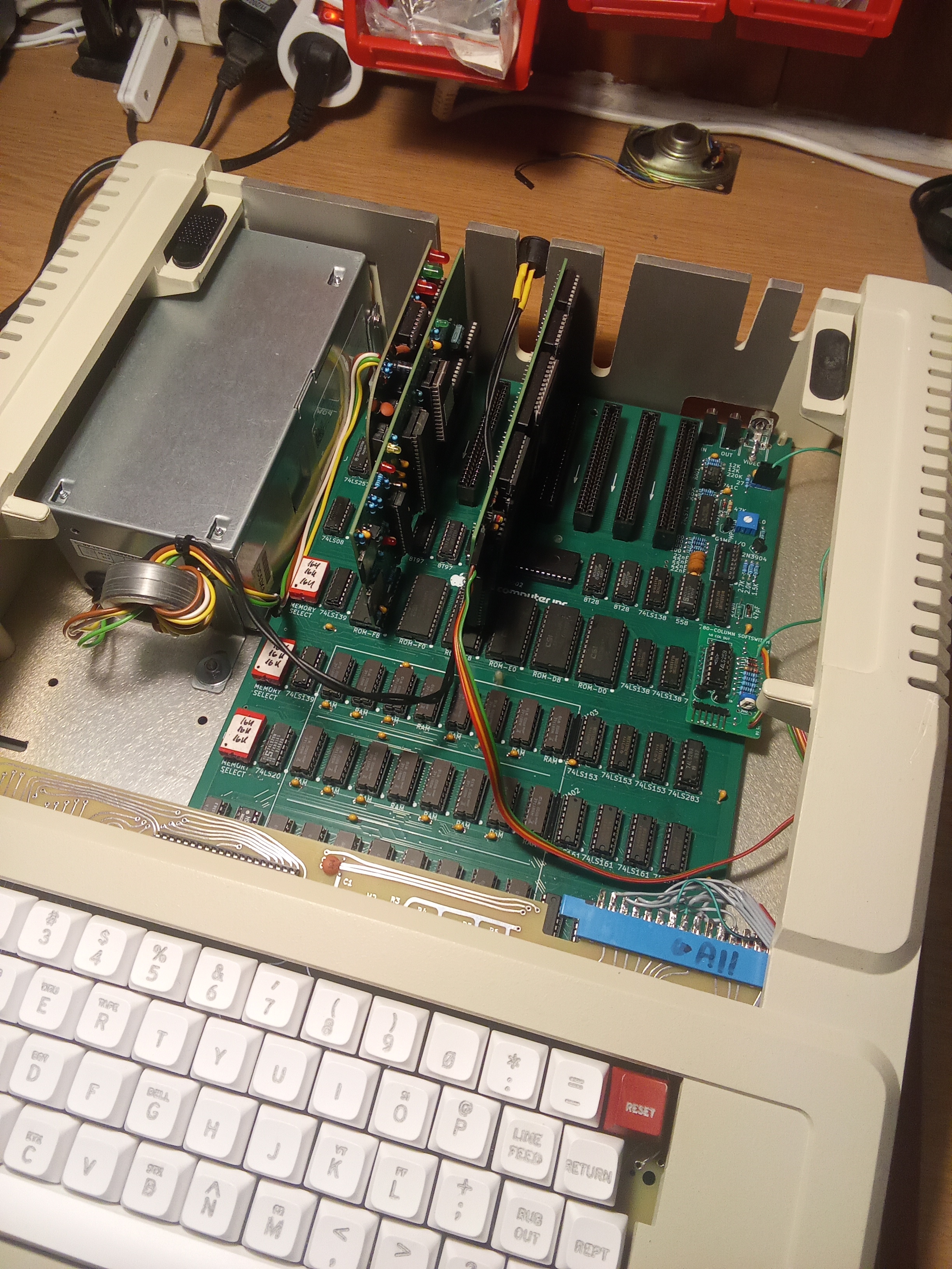
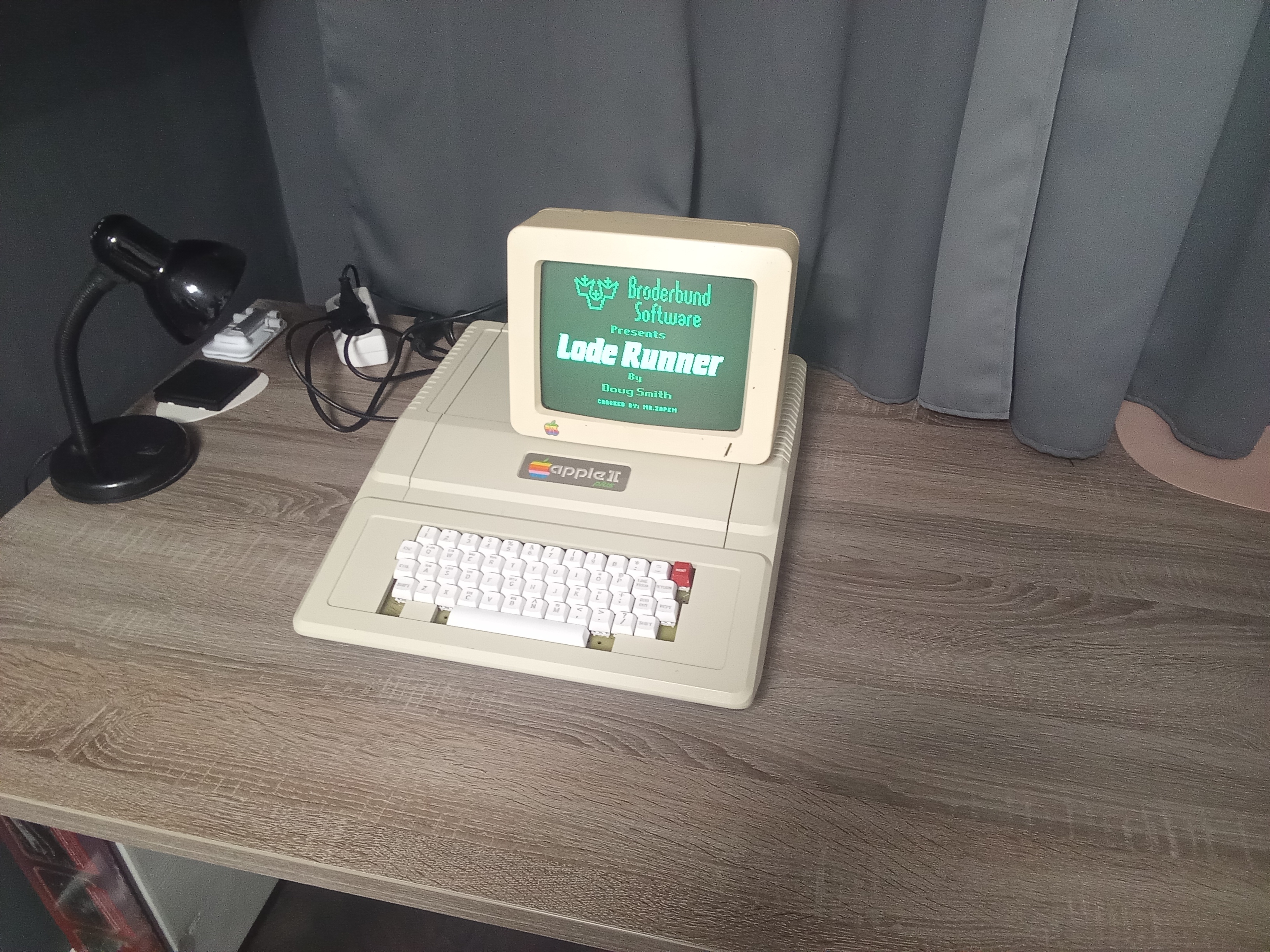
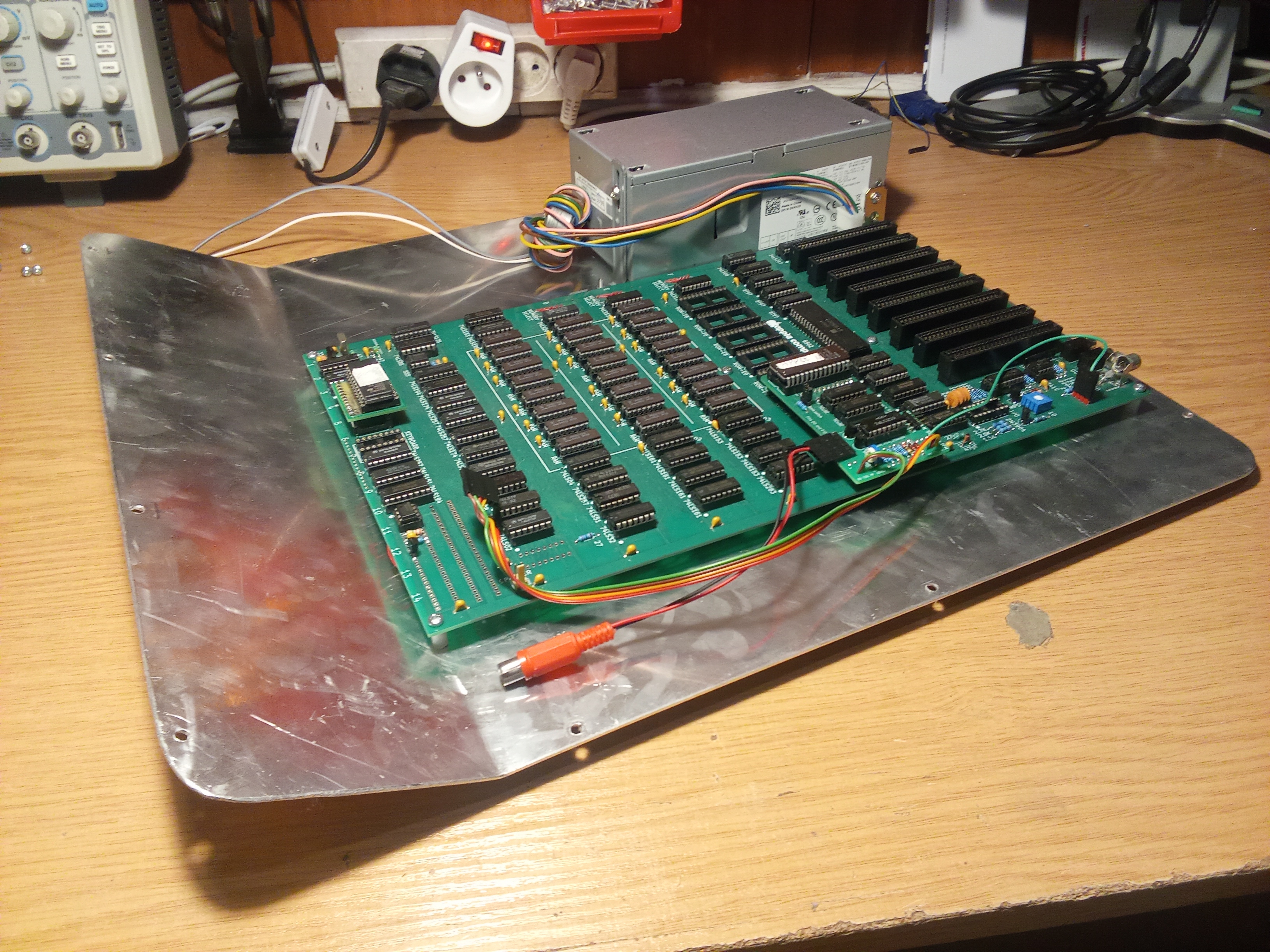
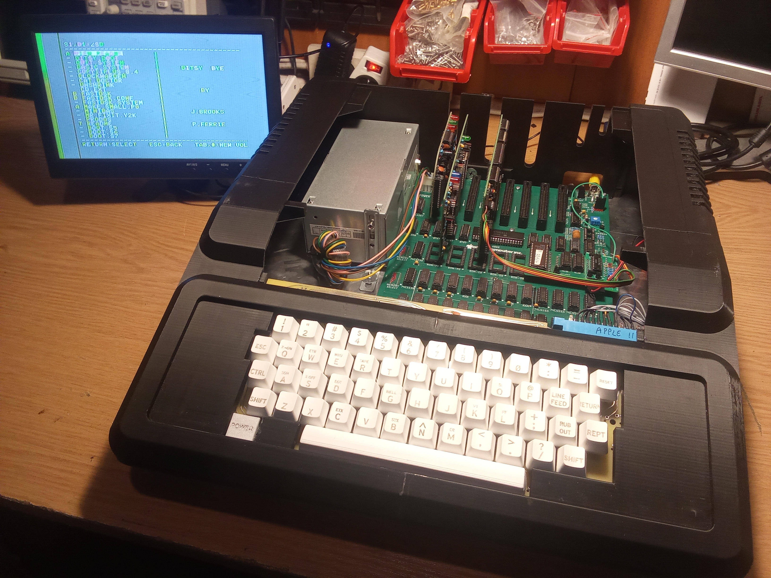
Some time ago, I received a Polish Apple II clone PCB (it was called Lidia) for repair – it's the gray PCB without soldermask. It was manufactured in Poland in 1984. I decided to build myself a modern Apple II rev. 0 clone using available Gerber files. One is mounted in the original Apple II Plus case, the other in a 3D-printed case. The power supplies are modified Dell ATX boards. It also includes a language card, an 80-column card, and a Disk II card. Keyboard's are a Datanetics replica with blank MX keycaps. The letters are laser-engraved.
I've attached a few photos.
Best regards,Mateusz SQ9PXB


Very nice, I have a few of the add on cards you show here but not gone as far as building a replica yet.
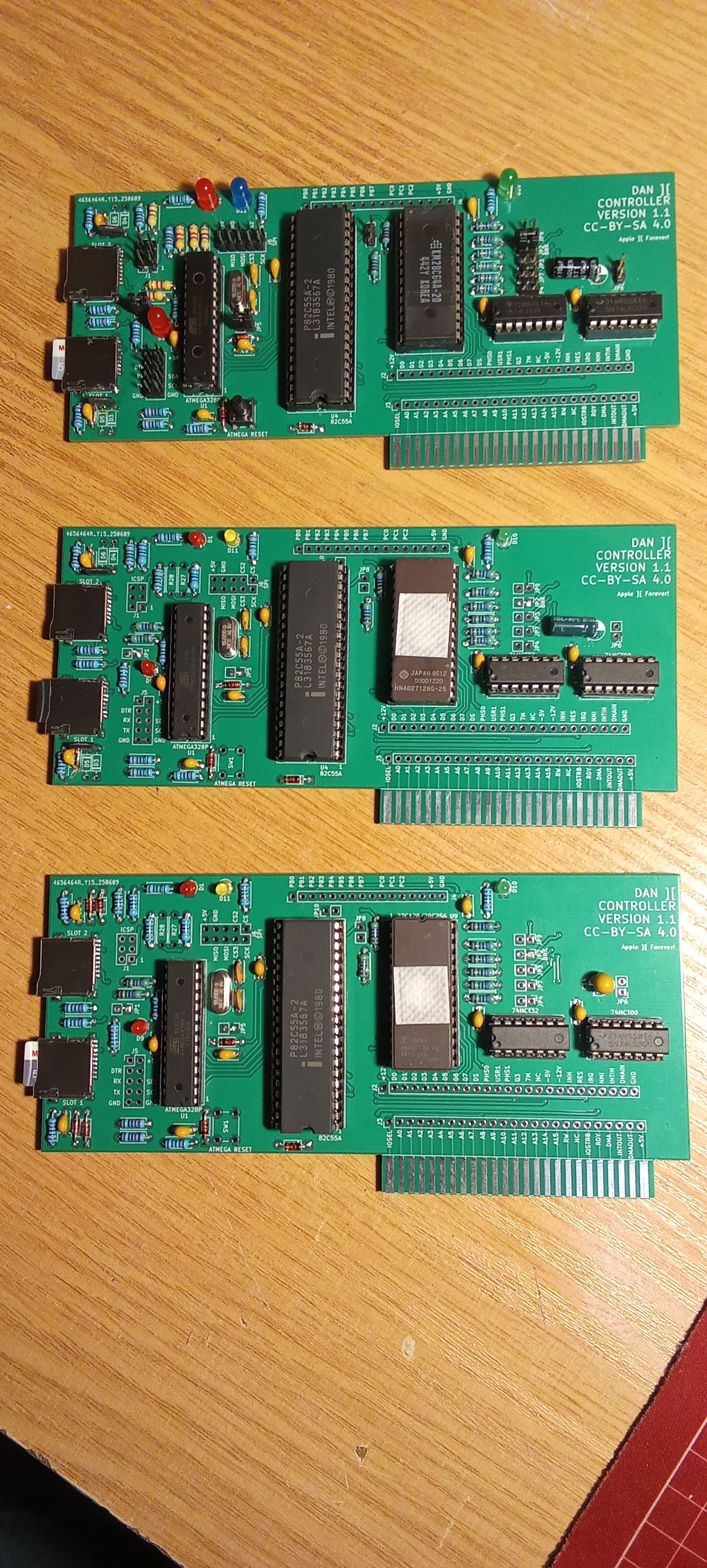
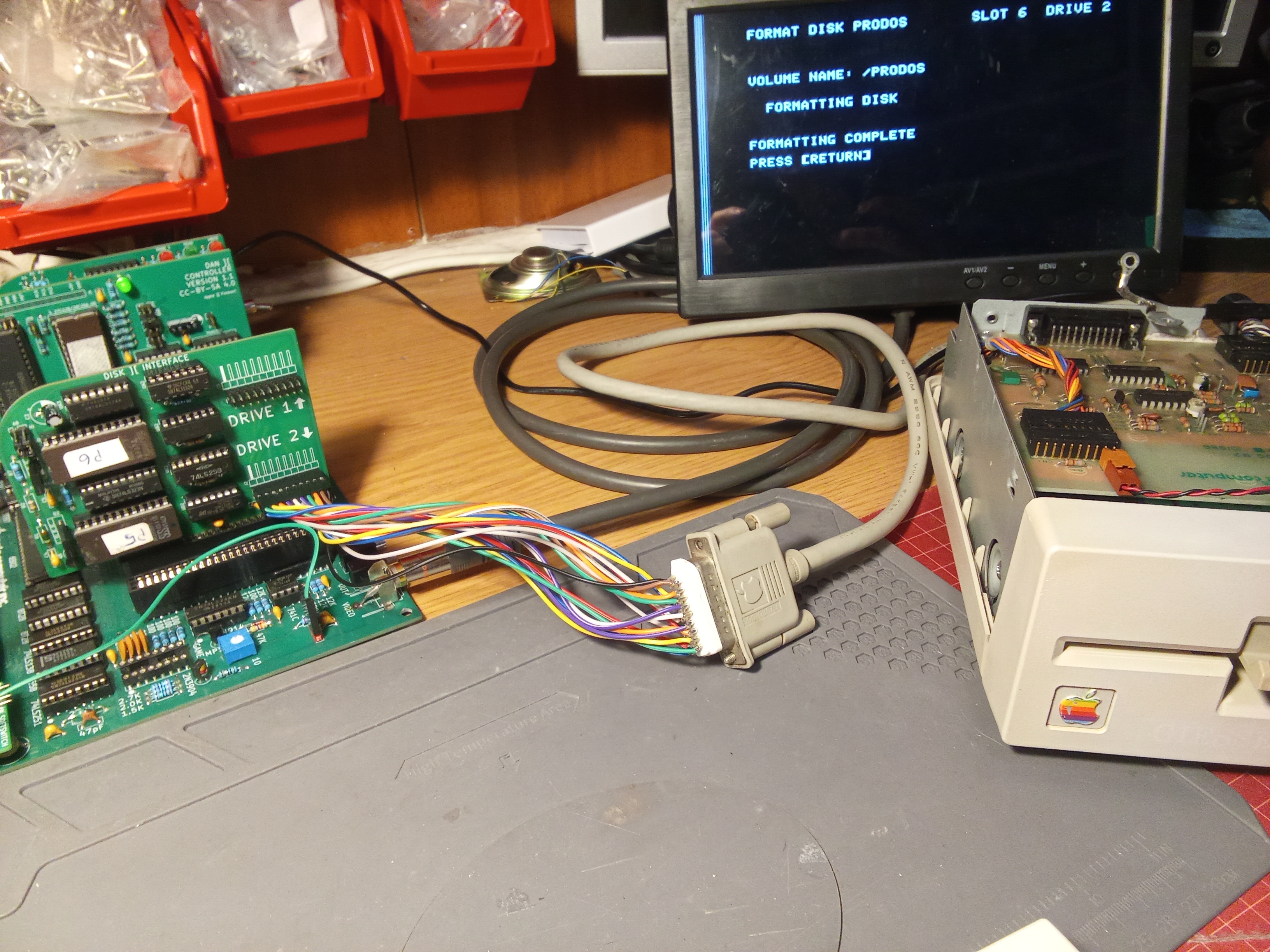
I notice on one of you dan II cards you are using a regulator instead of the diodes. What type of regulator is it that fits the footprint like that?
Derek
I noticed some modification on rev.0 on the right in the bottom row A. Could you tell me a little bit about it? Thank you!
IMG_20250515_173421_edit_363395650364811.jpg
This is for the experiment. I used an AMS1117-3.3V regulator to power microSD cards. But the original solution with two diodes (giving a voltage drop of about 1.4V, which with a 5V power supply gives about 3.6V for the microSD card) also works well with most microSD cards.
DIP8 is an NE555 timer for CPU autoreset (rev 0 must be always manually reset after power-up).
DIP14 is a 74LS74 flip-flop from original position A11 of rev 7 or II+. It improves the display when switching video modes.
Both modifications are derived from the Apple II+ schematic.
Regards,
Mateusz SQ9PXB