
I was having a bit of fun with my Apple III connecting it to a FloppyEmu (and to a normal Disk II drive). My Apple III only had the single internal drive so far. It really needed an extension...
Since I wanted a convenient and safe solution for the connection, I made a simple adapter. It's basically the Apple III equivalent of the D-SUB to 20pin IDC adapter for Apple II, which BMOW sells with every FloppyEmu. Sure, Apple III with FloppyEmu is certainly a niche application, but hey, so is any retrocomputing anyway. Maybe someone else is interested after all. :)
Some background (what you may or may not know...)
The Apple III has two 26pin box headers as ports for internal and external drives. Their lower 20pins are identical to the Apple II's Disk II connector. The upper 6pins are Apple III specific. The Apple III needed more pins, since it supports up to four 5,25" drives.
And it added a signal for a hardware feature to detect disk swaps: they changed the logic of the write-protect signal, so it became sticky. Removing a disk from a drive inevitably toggles the write protect switch (no matter whether the disks were protected or not). The Apple III drives used this to keep any new disk write protected (even if the disk itself wasn't), until the OS recognized and acknowledged the disk swap. A nice safety feature to prevent accidentally overwriting a disk, when the user swapped disks while the OS wasn't expecting it.
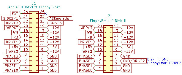
But then the Apple engineers needed to add yet another signal to the connector: to disable the new disk swap protection feature. The Apple III had to be able to emulate an Apple II. And since Apple II software doesn't know how to handle the "sticky write-protect" feature, the drives had to revert back to the original Disk II behaviour in Apple II emulation mode.
I guess, that's a well-known story. But I always found this detail about adding logic for a corner-case, and then requiring even more logic, just to disable the extra feature again, was quite telling about how the Apple III project worked as a whole (and it reminds me of so many futile feature discussions I had with product managers in my own day job...).
Anyway, back to FloppyEmu
Steve (BMOW) has a blog post on connecting his FloppyEmu to an Apple III. He doesn't sell Apple III adapters though, and doesn't officially support it - since he doesn't have an Apple III - and there are too few machines out there, so it's not worth it.
However, it will still work and all you really need is a 26pin ribbon cable, a 26pin IDC connector at one end, at a 20pin IDC connector at the other (stripping 6 wires). Just connecting the 20 identical signals is enough (only if you do it right, that is! :) ). That will work, since the extra pins are not strictly needed by the Apple III to work with a drive. The disk electronics, mechanics and low-level sector format are otherwise unchanged.
However, swapping cables was not a convenient solution for me. It would require me to disassemble my FloppyEmu enclosure every time I wanted it to switch between Apple II and Apple III. Same issue with the Disk II: I don't want to disassemble a drive, just to swap cables, so I can more conveniently copy disks on the Apple III. Also, the simple cable wouldn't be able to support FloppyEmu's "dual drive" feature - where it is emulating two drives...
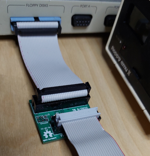
Well, and making a proper adapter is more fun anyway. :) Long story short, I made this simple PCB:
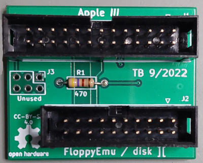
It can be connected to the Apple III's external disk port, using a simple 26pin ribbon cable. And it provides a 20pin connector for the original disk II or FloppyEmu ribbon cable. No disassembly or swapping cables required. It can also be used to connect to the Apple III's internal disk connector. That, however, requires to open the Apple III machine, of course...
Well, but does it really work?
Of course it does.
I have tested the combinations - using the FloppyEmu as internal or dual external drives. And using a Disk II as an external Apple III drive. When FloppyEmu is connected externally, the Apple III now even has 3 disk drives (Wohoo!).
Configuring a three-drive Apple III: SOS, SOS, ...
Two-drive configuration (one internal + one external drive) worked out of the box. But I was briefly struggling to make the third drive work (FloppyEmu as an external drive in dual-drive emulation mode). Until I found out, that the Apple III will not autodetect the number of its drives, like the Apple II does: no, you have to reconfigure the "Sophisticated Operating System (SOS)": load the "system utilties" disk, enter the "system configuration program (SCP)", select "read driver file", load your ".D1/sos.driver" configuration, select "change system parameters", "change the number of drives" to 3 (it was set to 2 on mine), then select "generate new system", write the configuration to ".D1/sos.driver". Finally reboot. Done! Now all three drives do work...
Oh, and as recommended, don't forget to make a backup of your boot disk before reconfiguring anything. Since, if that goes wrong - you're otherwise stuck with no boot disk. For example, if you forget to "read the driver file" before "generating the new system", then the new configuration will not contain a character set. The Apple III has no video ROM, but a character memory, which is loaded by software. So writing a new configuration with an empty character set really sucks (ask me how I know! :) )

Anyway. It all works now. And admittedly all this hassle with "SCP" was only necessary to make a third drive work. In any case, having the FloppyEmu option makes testing new stuff with the Apple III much more convenient...
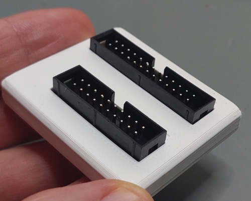
And, btw, I also made a simple 3D-printed box which completely covers the PCB (just to be safe):
If anyone else was interested in connecting an Apple III to FloppyEmu - the project and Gerber files, and some even more detailed descriptions are in my github project:
https://github.com/ThorstenBr/AppleIII_diskII
Also, I also have 2 or 3 PCBs left, if anyone else had an Apple III + FloppyEmu and was interested. I do live in Germany though, so mailing these anywhere is really economical for EU destinations only (nowadays, the minimum postage of sending anything overseas is more than the total cost of ordering a complete custom batch of PCBs directly from China. Crazy, but true...).
Apple (I)II forever!
Cheers! :)
That's dedication.
I don't have an Apple ///, but I applaud your love of the platform.
More versitile and affordable drive options might spark more interest in the III. Great Work.
Thanks. Always good to see something Apple /// related. Nice work. I will probably order a few boards myself, they will be a useful addtion for connecting other devices.
And great info, the disk switch thing was quite a complicated implementation in the end. One other interesting fact for that is the Duodisk includes the diskswitch circuitry on its analog board.
/Rob
I have an Apple ///. I'd love to make one of those adapters. I actually made a real simple one with just cable and crimp style IDC connectors, but that one looks better.
Well, I just ordered some PCBs from JLCPCB... So I will try making one.
Thanks for the kind words. And good to see others interested in the same niche stuff... :)
@rjustice: Wow, I had never noticed that the DuoDisk contained the extra logic. But you are absolutely right. There it is - the flipflop (LS74) for the disk-swap detection, which Disk II's don't have:
DuoDisk_FlipFlop.jpg
I was never able to find schematics for the DuoDisk. It's extremely similar to the Disk II, of course. But now it's obvious, it's even closer to the Disk III.
A while ago I also made an adapter for the DuoDisk, so I could switch between DuoDisk and FloppyEmu at my Apple IIe without swapping cables. Looking at the design again: indeed there is one pin at the DuoDisk, which I then believed to be a ground pin. The DuoDisk cable to the IIe has it hard-wired to ground. However, looking at the DuoDisk PCB again shows that pin 21 of its D-SUB connector is actually routed to the "reset" input of one of the LS74 flipflops. And that exactly is what the Disk III schematics show for the "A II emulation" pin. So the DuoDisk really contains the Disk III logic - which is always forced to "Apple II emulation mode", since the relevant control signal is hard-wired to ground when connected to the II.
That is really interesting. Was the DuoDisk also used as an external drive for the Apple III or other machines than the II? Otherwise seems to make no sense that they included the extra logic, just to have it always disabled through the fixed cable harness...
And since I just had another closer look at the Disk III schematics again, I need to correct on detail from my first post. The disk swap detection of the Disk III (and the DuoDisk... :) ) does not cause the write-protect signal to be sticky. It's more clever than that. It forces the drive's "read data" output to be sticky (always high), until the disk swap is acknowledged. That still prevents the OS from writing to a disk, when that was unexpectedly swapped (since the 6502 always reads first, to find the exact timing to hit a specific disk sector for writing). But it also provides the same protection when reading a disk: the first read after a disk swap always behaves as if no disk was present. Pretty clever!
I believe the duodisk 25 pin connector has the same pinouts as the Apple///+ external drive connector. On the ///+ they changed it to a DB25 connector. This means you can connect a Duodisk directly to the disk port on the ///+ with a straight thought 25 pin cable and get external drives 2 & 3. I have not tried that myself, but I have read that someone has done this successfuly, I think that might have been on FB.
Info is really scattered around the internet, you can grab the schematics for the Duodisk analog board here at Bitsavers:
http://www.bitsavers.org/pdf/apple/disk/5_inch/
/Rob
I wonder how well a Unidisk 5.25 would work with this Apple /// adapter and this cable from IEC:
http://www.iec-usa.com/cgi-bin/iec/fullpic?ezV2CFGH;L1565;8
Rob, thanks a lot for the link to DuoDisk schematics. I have actually been looking for those a while ago - and was unable to find them. They do not seem to be on asimov. But bitsavers indeed has a nice collection of those.
And now the logic of DuoDisk is pretty clear. It does have the Disk III's disk swap detection logic. However, ... it's complicated... Obviously they were trying to save chips after all. The disk swap logic normally requires two flipflops - so a full LS74. It would need that for each drive. But on the DuoDisk they just used one LS74 - for both drives. The schematics show the DuoDisk simply uses a logical-OR to combine the two write-protect signals of both drives - and uses this for the disk swap detection logic. So the DuoDisk cannot distinguish disk swaps of its drives. It would trigger as soon as any of the two disks was swapped. And, interestingly enough: if a write-protected disk was present in any of the two drives, then a disk swap could not be detected on the other drive. Seems to be a weird limitation - but it's pretty clear when looking at the schematics. I think I will make a test on my bench at some point to verify. Seems interesting. :)
@sj: The Unidisk will probably work - in the same way as my Disk II did work with the adapter. However, there also seems to be quite a variety of 5,25" UniDisks out there. The bitsavers site shows PCBs and schematics of a 5,25" Unidisk with a DB25 connector (two DB25s actually, so you could daisy chain them):
Unidisk_PCB_1.jpg
These would not work with the IEC adapter - since the adapter has a DB19 connector. Those Unidisks also have the disk-swap detection logic.
But apparently the 5,25" Unidisk variant with DB19 connectors is also very common - like this one:
Unidisk_PCB_2.jpg
This Unidisk would fit the IEC adapter from the link above. However, as this photo shows: this PCB does not have the LS74 flipflop, so no disk swap detection. Seems to have the same drive logic as the original Disk IIs.
D25? On a Duodisk... yes on the drive itself but DB19 on the end of the cable that plugs into the controller.. but all the Unidisk 5.25 and Apple 5.25 Drives I have are DB19 on the cable end and the pass-through out the back for daisy chain.
I don't think I've ever actually seen a Unidisk 5.25 or Apple 5.25 Drive with DB25s on it. Anyone actually have one like that? I've got at least 5 or 6 of the ones with DB19s.
Here is one of my drives, this one is an "Apple 5.25 Drive":
apple_5.25_drive.jpeg
Indeed an image search does not show a single Unidisk with DB25s - except for the PCB design photos on bitsavers. The DB25 Unidisk and DuoDisk schematics on bitsavers have dates: they were both drawn in December 1982, and checked & approved in Feburary 1983. So these were early designs.
My take on this: The engineer who made the original design did the obvious thing: he based the design on the Disk III, so included the extra logic and extra signals which the Apple III had. This required the DB25 connector - which would also fit the Apple III+. The extra signals wouldn't fit on a DB19.
Then they quickly realized the Apple /// wasn't selling. But the Apple II(e) was, which had no use of the extra signals and logic. So they were just wasting money for nothing: extra logic, wider connectors, and even cables with extra leads. So they redesigned the Unidisk, dropped all the extra stuff the Apple II didn't need, which also allowed them use DB19s on the device end and required cables with fewer wires. And they also dropped the expensive second connector for the pass-through, and replaced it with a cheap pin header. Probably saved them a few bucks on each UniDisk drive. And the image search showed a lot of UniDisk PCBs which have a "copyright 1986" on them.
I cannot find any photos of DuoDisks with DB19s, so apparently they never redesigned it. The extra cost probably hurt a bit less on the more expensive DuoDisk.
I think you are right on all of that MacFly. I think the UniDisk designs with the DB25s were probably very early and probably never reached production. They might have made a few prototypes which may or may not still exist. The cost reduction at the time makes sense. At that time the way Apple was buying parts like DB19 in huge volume they were probably cheaper for them than DB25. Not so today however, because basically only Apple (and products made to work with Apple) ever used DB19 in any major way, they are no longer being produced in volume and are thus expensive. A lot of people use interesting workarounds like male connectors made with pins soldered to a bit of PCB or cut down DB25 connectors. Female DB19 are more of an issue. We should be happy they aren't as rare or expensive as DB13 -- Atari used those on their 8 bit systems... and they are basically near unobtanium.
I'm also guessing that it is also correct that the DuoDisk just didn't get redesigned. The cable for it probably only had 19 conductors in it because of the DB19 end at the controller and the difference in cost for the DB25 on the drive side probably only a few cents a unit. The DuoDisk was probably projected to sell fewer units, and as noted it was more expensive so it probably didn't merit the extra work.
When the //e came out it really was the final nail in the coffin of the ///. It took away most of the reasons why someone would pick a /// over an Apple ][+. Standard full upper and lower case keyboard and 80 column display. The original //e didn't have a numeric keypad, but it was easy to add. And the memory on a //e was easily expandable past even 128k with 3rd party cards like the RAMWorks. Pretty quickly it was expandable to more memory than the /// even. The /// still ran at 2MHz which was faster than a //e, but there were accellerator cards from AE, Titan, McT, etc., which were even faster (3.5 to 4MHz). The /// was enough more expensive that you could probably buy a //e and add a RAMWorks and an accellerator card and be about the same price or maybe even less. The /// might have had a chance if software developers had really built a lot of /// specific software that took advantage of its features. And while there really was quite a bit (compared to what existed for a lot of other 8 bit systems at the time, the Apple II excepted), it also wasn't long before a lot of those apps were adapted to run on the //e, like //e specific versions of apps like Visicalc, 3 EZ Pieces became AppleWorks, and WordJuggler //e came out, etc. If the Apple ///'s emulation wasn't limited to basically a bog stock 48K ][+, it would have helped the /// a lot also. Apple intentionally limited it early on to try to encourage more /// specific development. That may have worked at first but in the llong run it hurt the ///'s sales. The Titan ///+//e helped that, but it was kind of too little too late, and it wasn't cheap.
Here's a longer update on Apple III drive logic and adapters... I do no longer recommend the simple adapter cables ("just strip the top 6 wires") to connect a Disk II or FloppyEmu to an Apple III. The same is true for my original design of the adapter PCB. Those simple adapters are fine - but only if you attach a single drive to the Apple III only. There are issues when you connect more than one drive. The Apple III has another twist, a special feature, which Apple IIs do not have. And that requires a bit of extra logic to be handled properly – otherwise disks may get corrupted or reading may fail...
I have made an improved version of my adapter PCB for the Apple III, which now properly considers the Apple III-specific drive control signals. You can find the updated schematics and PCB in my GitHub repository.
Adapter_pcb.jpg
Maybe this Apple III “special feature” isn’t really new to some of you experts. But since I saw a couple of other posts “on the internet”, suggesting to use simple “Apple III to Disk II/FloppyEmu – just strip the top 6 wires” cables – and since I initially also overlooked this detail and stepped into the same trap, it’s maybe still worth a more detailed explanation.
Those interested in an “Uncle Bernie-like deep dive” into Apple II(I) disk control signals, can read on (only comparable in blog post length, but in no way matching Bernie’s famous level of sophistication, of course… ;-) ).
Brief recap
As discussed previously, the Apple III has the same drive signals as the Apple II (though a few extra wires). The common signals directly control the stepper motor, a read and a write data bit, enable the write head and return the status of the disk protection sensor. The general concept of the Apple II/III drive interface is that all the signals are shared between all drives. All drives are connected to each signal concurrently – nothing is switched – except for the “drive enable” signals. These signals are the only signals which are specific to a drive. And there is one “drive enable” signal per 5,25” drive (let’s just ignore 3,5” drive select logic for now...). And this is the only pin which differs between the two connectors of a Disk II interface controller.
How Apple II 5,25” drive control works
On the Apple II, the "drive enable" signal actually does two separate things:
Hence, on the Apple II there is a simple rule for the controller card - like the disk II interface: only one drive may be enabled at a time. Never more than one – this would otherwise cause conflicts: multiple drives trying to transmit data over the same wires, multiple drives reading/writing the same data to their disks etc.
So, what's the "magic" Apple III extra?
The Apple III has the same signals as the Apple II as described above. It has a few extra signals to detect disk swaps and prevent writing on a swapped disk (we had discussed these earlier). When running in “Apple II emulation mode”, it will actually control the "disk enable" signals in exactly the same way as an Apple II. Sure makes sense to be completely compatible…
However, when the Apple III runs in native mode (rather than in “Apple II emulation”), the logic is slightly different:
But why? Why did they do that?
The idea becomes obvious as soon as you start using multiple drives attached to an Apple III concurrently. The Apple III is able to keep the motors of multiple (at most two) drives spinning at the same time, while still being able to communicate with exactly one of them. The Apple III does so by keeping the "drive enable" signal of the internal drive active, while also enabling one of the "drive enable" signals of an external drive. And it then uses the extra signal "INT/EXT" to toggle communication between its internal or external ports. This only works with the internal and one external drives. It’s not possible to keep multiple external drives spinning...
The obvious advantage is to speed up disk access when switching between internal/external drives. When the drives keep spinning, the Apple III is able to switch between drives with no delay. Unlike the Apple II, which always needs to briefly wait whenever access is switched, until the selected disk has spun up. The feature becomes most obvious when you start a volume copy, for example with Apple III SOS disk utilities. Both drives keep spinning, the machine just reads & writes back to back from the drives – with no gaps. The feature is also occasionally visible with other software, when you quickly switch between drives (apparently SOS has a brief timeout, so keeps a recently used drive spinning briefly, in case it would be accessed again).
Adapters and FloppyEmu
I have updated my adapter with a simple logic gate. This makes sure the connected drive (FloppyEmu or Disk II) is only enabled when both conditions are met: the "drive enable" signal is active and the INT/EXT signal also enables the drive accordingly. For FloppyEmu this is a perfect fix. FloppyEmu’s emulation instantly "spins" at the correct speed whenever it is selected anway. Keeping a virtual disk spinning would not result in any advantage anyway...
Adapters and Disk II
With a real Disk II drive the updated adapter is still not perfect. It fixes all serious issues like corrupted disks – or communication conflicts. It also works perfectly as long as you only access a single drive or read from the Disk II. However, when drives are used concurrently, the adapter now disables the Disk II when the INT/EXT signal selects the other drive for communication – so it stops spinning. And this is not what the Apple III expects: unlike FloppyEmu, a real Disk II is inert and its motor will need time to accelerate...
Luckily the Apple III is forgiving when reading: even though the drive needs unexpected extra time to speed up to normal speed, SOS doesn’t complain and just accepts the brief delay. So a Disk II connected via the adapter still works for reading – though it will be slightly slower than a real Disk III.
However, SOS notices that something is up when writing: it does not accept any delay whatsoever. If the selected disk isn’t instantly ready after switching drives, SOS complains with an I/O error. To fix this issue, a more “complex” adapter would be required: one which isolates all drive control signals from the drive, so the Disk II could remain enabled (spinning), without interfering with, or getting confused by the drive control signals (stepper motor etc). That could be done. It would require much more components though – and wasn’t really worth it for me (indeed, I really only wanted a perfect adapter for FloppyEmu anyway, the option to connect a real Disk II to Apple III was just a nice gimmick for me – and it still “mostly works”...).
So, how good is the “superior Apple III technology”? :)
It’s clear that the Apple engineers spend quite a few logic gates on this feature. In fact, the Apple III mainboard has separate logic gates for drive selection in native and Apple II emulation mode – and they even added an entire IC (mulitplexer) just to switch between the two slightly differing register sets of the Apple II/III drive select logic.
I did a few “benchmarks” with volume copies:
So, the benchmark suggests the Apple II loses a bit less than a second whenever it needs to switch between drives. This matches a comment in the SOS sources I saw, mentioning a one second delay/timeout when spinning up an idle drive.
So, Apple III was better – right? Right??
Well, it did have an advantage. But using multiple disk drives concurrently probably wasn’t really a killer feature even back then. After all, they had started introducing the ProFile harddisk with the Apple III – providing a completely different level of performance.
And, fun fact, even if you were interested in volume copies: “Copy // Plus” actually does a volume copy of the same disks in lightning fast 36 seconds – and that’s on the Apple II (only switching between drives twice, so making use of my Apple II’s 128KB of RAM). So, slightly smarter software actually easily beats the stock Apple OS utilities, even with all the special Apple III “keep drives spinning” logic.
So, was it worth it - all the extra logic and wires? I guess the answer for Apple back then was: probably not. And that’s why they dropped all the extra Apple III drive logic stuff when they made the Apple IIe, the DuoDisk etc – and they reverted to plain Apple II drive control signals...
Dang it... I built a few of the simple version... Now I'll have to make some more of the new design. Thankfully I think I still have a few of the IDC box connectors...
Thanks for the detailed explanation MacFly, that was an interesting read. And not somthing that I had come across before, always good to understand something new and unique on the Apple III.
/Rob
@macfly, I've been trying to get the Fujinet floppy emulation working with the Apple/// and bumped into something I thought I would share with you.
I was just using a direct cable (20pin to 26pin) connected to the internal drive port, as I have not built any of your adapters yet. What I noticed is that the A3 is using a 74LS257 to switch the enable1 for the internal and external drives. When this LS257 is not enabled, ie the drive motor is off, it goes into a high impedance state rather than a specific high or low. I had to put a pullup on the enable1 line to get the Fujinet to work. It seems you have not noticed any issues with the adapter, perhaps a pullup on this signal might be worth considering.
/Rob
Good point. I didn't see any issues with my adapters so far - but it's also using an LS-TTL logic IC, where unused (not actively driven) inputs are high anyway. But pull-ups would certainly be required if CMOS logic was used (which is possibly the case with Fujinet).
Thanks for this detailed and clear analysis! I've owned an Apple /// since the (very) early 80's - although it has been in storage for a long time. Back then (!) I tried to learn everything I could about how the hardware worked, but never delved much into the emulation mode. I need to unbox it and see if I can get it working again.
-- rt --
Right now Joe's Computer Museum is re-issuing a clone of the Tital /// + //e card set. This realy makes the /// a much more formidable machine as far as emulation goes. The original /// Apple ][ emulation only does a 48k ][+. No 80 column support, not even a 16k RAM card for IntBASIC, etc. No lower case even. Really extremely limited. I personally think the /// would have been a lot more successful if Apple hadn't limited the Emulation mode so much. Their theory apparently was to try to encourage more native /// apps. That didn't appear to work out so well. Between 1980 and 1982 people seemed to prefer to buy a ][+ and then add the expansions they needed like RAM cards, 80 column cards, even accellerator cards. As expensive as the /// was you could add quite a bit to a ][+ and still spend less than a basic ///. And have access to a much larger software library. If the original /// Emulation was a 64k ][+ with 80 columns, even if not Videx compatible, then people might have been willing to spend the extra $$$ for a /// to be able to run a lot of the ][+ software library and a few of the really excellent native /// apps. In 1983 when the //e came out, a lot of the ///'s advantages disappeared since the //e had 80 columns, lower case, better support for more than 64k of RAM, etc... Of course by then the /// was pretty much already considered a flop and it was probably too late for it. Apple's failure to deliver things like higher capacity 5.25" drives which had been planned for the /// didn't help either. By the time 3.5" drives came out after the Mac introduction in 1984 the /// was already more or less considered dead and very quickly the whole Apple II line was just a cash cow for Apple to milk while they tried to launch the Mac. Of course hindsight is 20/20 but it is almost painful sometimes to look back and see Apple's mis-steps and what could have been if they'd executed as well in the 1980s as they did in the 1970s. Even then the Apple II had a great run... but the /// really should have been a much more worthy successor than it was.
Anyway... back to the /// + //e... It does emulation the way the /// should have to begin with... It will run most software that will run on a 128k //e. From what I've read if you upgrade it with a 65C02 and some changes to the software to support MouseText and the Enhanced ROMs it's even more versatile.
Anyway, I went ahead and ordered one of the board sets from Joe to put into my ///. I'm thinking it will be fun. I'd been thinking of selling my /// but this may make me keep it around.
If I hacked the A/// motherboard to add a wire from the external floppy connector to the internal floppy connector on pin 22 for the enable 2 signal, do you think I could use FloppyEmu as .d1 and .d2? (or is this going to fail because the int/ext signal will still be wrong for .d1?)
It wouldn't work for the very reason you already noticed. Originally I had the idea to add a jumper cable to connect the drive 4 signal to the unused secondary drive pin on the internal connector. So the internal connector would allow connect drives 1+4, while the external connector could still be used for drives 2+3 as normal. But the drives may only communicate when both signals are enabled - the INT/EXT signal and the particular drive signal. The logic of the INT/EXT pin is inverted between the internal and external connectors. And the machine assumes drives 2,3 and 4 to be connected to the external connector.
You could rig an adapter, of course, which again inverts the INT/EXT pin and uses that to decode the "drive enable" signal for the secondary drive, while the original INT/EXT signal was still used to decode drive 1. That would allow to connect something like a FloppyEmu to the internal connector and use its "dual drive" mode.
So with some modifications it's possible. But personally I'm happy with an installed FloppyEmu as the boot drive (.d1), a separate real disk drive as an external drive (.d2) - and a DAN II controller card as a Profile replacement.
Thanks for the notes. I looked more carefully at the schematics and noticed pins 14 and 26 are also subtly different between the internal and external floppy connectors so my simplistic approach wouldn't work without a least a few more gates. Need to get my A/// up and running again before I think about investing $100+ in the floppy emulator.
Pin 26 is the very "INT/EXT" signal we talked about. Pin 14 is the enable signal for the first drive. So on the internal connector it's connected to the "drive 1 enable" signal, while it's connected to the "drive 2 enable" signal on the external drive. That, of course, differs as expected. So if you wanted to add dual-drive support to the internal connector, you indeed only needed to handle the inverted logic of INT/EXT signal, as discussed above (and install a jumper wire, to connect one of the three external drive enable signals (pin 14, pin21 or pin 22) to the internal connector's pin 22.
Quoting from above: (MacFly) "I'm happy with an installed FloppyEmu as the boot drive (.d1), a separate real disk drive as an external drive (.d2) - and a DAN II controller card as a Profile replacement."
I've been thinking about this some more now that I have a Dan II controller card running in my A///. Where do you put the FloppyEmu (physically) when it's replacing the internal floppy? Did you snake the ribbon cable out one of the I/O slots on the back?
Yes, through the I/O slot, that's about the only option (not involving an angle grinder :)). Or just using the FloppyEmu as an external drive (#2 or 3 only), and use it as a source to copy volumes to a real disk.
I suppose one could remove the internal floppy altogether and 3-D print a new top cover with cutouts similar to your custom disk II enclosure. Wouldn't that be something! [edit: May not be that involved. The 1.3" OLED on the FloppyEmu is about 35.5mm wide, and the existing cutout for the internal floppy's mechanism lever is about 40mm. ]
Is there any interest for a kit of this adapter? I have the blank pcbs and complete parts kit for 10 adapters.