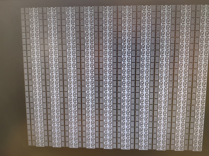
I am working on a Franklin Ace 1000 Apple ii+ clone that I picked up recently. While I have successfully repaired several other systems, I have never owned or worked on an Apple or clone system previously. Before booting it, I installed a new power supply from ReActiveMicro which seems to be working perfectly although 5v is a bit low at 4.77v. The system boots to a "garbage" screen. It generally displays a similar pattern to the first screen shot below but often there are random characters (sometimes blinking) scattered across the screen. There is no beep on boot. I will some list of the steps I have taken to try to figure out the issue after the screenshot and would greatly welcome any suggestions or wisdom.
1) Removed all ICs, put Deoxit in the sockets, and reinstalled the ICs. In the process, I found one ROM and two DRAM chips with legs bent up under the chip and not properly inserted into the socket. I fixed this plus cleaned the legs on many of the 4116 chips which appeared to be almost black although not visibly corroded in any way. I found the transister at G4 had been mashed down and a couple legs were shorted which I fixed. All of this resulted in no change.
2) Replaced all 4116 ships in the "C" row with NOS 4116 chips. No change. I had also swapped those from the "D" row into the "C" row and vice versa when I put the ICs back as a test and also no change there so I don't think bad ram in row "C" is the issue. I don't have a ram tester to be sure.
3) Tried a new 6502 processor. I did not think this was the problem but I had one so why not. No change.
4) I have a decent supply of 74LSxx(x) ICs that I tried. No change. I can supply details on this if that is helpful. I must have tried about 8 different types of 74LS ICs, some of which I tried in mutiple locations where they are used, with no change. Unfortunately, I have no way to verify the ICs I have are good although they are supposed to all be new so not sure how good a test this is. I certainly did not replace all 74LS ICs so if there are specific ones to try please let me know and I will purchase the ones I do not have.
5) I have a logic probe (but not a lot of experience using one) and I confirmed that the 6502 reset pin was high and only pulled low when I pressed the reset button with no change.
6) I removed each of the ROM chips one by one and booted replacing the last chip before pulling the next. No change except in one case that I will list below.
There are only two occassions that I noted any change to the general pattern of "garbage" I see on the screen on boot. The first was booting without any ICs in row "C" just as a test. In that case, the screen appeared very similar to the screenshot above but with only the "checkerboard" symbol in all places instead of alternating with the "@" symbol.
The other time that I noted a change was when I booted without the 2532 eeprom (maybe the character ROM? I cannot find much info on the Franklin system) that is located on the color daughterboard that fits onto the mainboard. When booting without that IC, the boot screen alternates between a completely white screen and one with alternating white and black vertical strips. It changes between the all white and the stripped screen at about one second intervals. I don't know if this indicates that the ROM is bad or whether that is just the normal behavior when it is pulled.
Thank you. All suggestions are appreciated!
From all of the testing you've done, I'd suspect the F8 Monitor ROM. Perhaps you can test it by reading in an EPROM programmer; or just buy or burn a new one.
I had that particular pattern on my Apple II+ when I first got it: click!
It turned out to be due to a defective RAM chip in position C3 (the very first chip of the lowest 16K row).
First, you are doing all the right things so far. For all practica purposes you can treat this machine as an Apple ][ Plus for troubleshooting this issue. Aside from some minor ROM changes thee boards are virtually identical. You will find a lot more info on the web for the ][ Plus than the Ace.
Screen text is stored in the lowest 16k ram bank so it must be populated and working or any results are unreliable. I would work that bank first. I have several 1000s and this has been a common problem.
second, I would never argue with Jeff Mazur He produces a FOM replacement tool called ROMX. Which is great as a ROM replacement and/or diagnostics tool. I would try a ROMX because I think it would be easier and more reliable than tracking down a good F8 chip.
Thanks for the plug 8bit, but it doesn't look like the ROMX would physically fit in the ACE 1000. Probably could be modified to work but too much trouble.
RAM is always the first thing to check, especially with these symptoms. But I trust that his replacement of the first row with all NOS chips as well as swapping with the second row has almost completely ruled this out. Not to say that one of the NOS chips could not be bad or a bad socket, trace, etc. could be the issue.
Thank you jeffmazur, CVT, and 8BitHeaven for your guidance and suggestions!
@jeffmazur - I looked up the F8 ROM and it is the one that I found had a bent up pin. It does not work with the pin properly connected but it suggests to me that someone tried to fix the system in the past and removed/replaced it. Clearly it is time to invest in an EEPROM programmer! I know that some models do not write older ROM chips due to higher voltage requirements so I will do the research to make sure I pick up a model (or an add on board) that will allow me to work with 2532, etc.
@8BitHeaven and @jeffmazur - The ROMX looks like a fantastic solution. If I am lucky enough to own an Apple II system in the future, I will likely invest in one.
@CVT - The screenshot from the RAM issue you fixed sure is close. While I did try other RAM on the "C" row, jeffmazur's comment about socket issues made me realize I did not look for bad solder joints or sockets. In fact, I didn't remove the motherboard completely from the metal baseplate. I will do so, do a close examination, and test out connectively on all traces to the RAM sockets at least in row "C".
So I am traveling right now and don't have access to any docs but here are my suggestions/random thoughts from memory.
1) Does the reset button under the front lip of the keyboard have any impact on the the display? Does the keyboard work after a reset?
2) The Ace 1000 actually used 2 different motherboards and the later Ace 1200 board sometimes got swapped into an Ace 1000 for repair purposes. You might have any one of 3 boards. Some (mostly early machines) used a large color killer board mounted on top the motherboard up near the keyboard, that could change things quite a bit. A picture of your board would be helpful.
3) I think the chargen was a 2716 and the 2532 was used in the color killer. I don't think these are pin compatible. That might have something to do with the bent pin as a bank selector, without access to docs, I dont' know. Adrian's Digital Basement on youtube had a video on fixing the Ace 1000 with some some of the best info on the Color Killer and associate topics I have seen. It was a muli part series and I think the part most interesting to you is in the part where he also fixed the keyboard. Or it might be that the chargen is simply bad or trashed because the it was the wrong one and got zapped.
4) The alternating block and inverse @ symbols indicate screen memory is a repeating pattern of 255, 255, 0, 0. It might be the RAM is fine ( although the occasional random different character might suggest some random failures) but the memore decoding is bad. I think row F' had the 74LS logic related to that decoding so you might start swapping chips there. Note row F contains the last 16K RAM bank normally found on the language/memory expansion card of the][ Plus. You can easily match relevent rows by matching chips of each row between the Ace and ][ Plus.
5) It might not wbe 'broken" at all. The 255, 255, 0, 0 pattern might not actually be stored in the RAM dedicated to screen memory (starting at $0400) , but the dot pattern displayed by the chargen only matches the 2 characters you are seeing, That is, the chargen always displays only dot pattern for the characters "block" or inverse @ for all the characters. This seems likely if the bent pin state is wrong and only the lower half of the chargen ROM was burned and not all banks were written with true charater bit patterns. This seems not very likely because the screen should be filled with spaces (ASCII 32 + 128) so all characters should be the same, not in alternating pairs. I'm thinking this might be a secondary problem, assuming we are not dealing with a single issue. This still points me more toward bad RAM or decoding as more likely.
When I get back I'm going to check into mods needed for ROMX in a Franklin Ace 1x00.
Good luck and keep us posted on your progress.
@8BitHeaven - Thanks for your additional suggestions. I had a chance to take over the kitchen table today to work on the computer and hopefully I am close - at least to solving the primary issue. For the sake of narrative, I'll provide some details and then get to what I discovered. In answer to some of your questions:
1) The reset button will pull the reset pin on the CPU low but there is no other apparent effect. I forgot to mention that I replaced the foam and foil disks in the keyboard before even replacing the power supply (I'm an optimist) so theoretially the keyboard should work. However, none of the keys have any detectable effect before or after a reset.
2) I have the motherboard with 64K of 4116 sdram and a color daughter board. I believe it's the same version as Adrian Black's which is fortunate which I will explain shortly. Like Adrian, I could not find schematics or other resources for this version online. I removed it from the base plate and found the reverse side to be extremely clean with no signs of cold or cracked joints, bodges, or any rework. I checked connections between chips in the first bank ("C") bank of RAM and found no issues. I'll paste a photo of the motherboard just below.
Ace1000_front.jpg
I added the blue tape on two of the 2716 EPROMs temporarily because their stickers had fallen off. I next decided to try yet another set of 4116 RAM in bank "C". The only effect that this had was to change the screen that appears on boot. Now, thecolumns of "checkerboard" characters that alternated with collumns of "@" symbols (see photo in my first post) have changed to all "W"s. I decided to leave the new RAM in place for now and readdress it later.
I next pulled out the T48 (TL866-3G) programmer that arrived yesterday to look into the ROMs and the other 74LS ICs I had not been able to test previously. To cut the story short, I figured out how to read the ROM chips and I compared their contents to the images that Adrian had posted to archive.org. This is where it is fortunate that I have the same motherboard as he. First, that he had them to read and post theimages and secondly that they are exactly the same version as mine. All of ROMs compared exactly except for the one marked "G2" in the photo. It contains "00" at every address. I was able to load Adrian's G2 image and attempt to program the chip - which completes as "successful" but the verification immediately fails. The 2716 is faulty. While I was at it, I went ahead and used the "Test IC" feature to confirm that the 74LS ICs I was not able to replace previously tested out fine.
So, the next step is to order a few 2716 EPROMs and see if I can create a good G2 ROM.
Just realized I made a mistake in my last posting. The ROM that was faulty was "G3" (second from the left on the photo) and not "G2".
Just saw this thread, apologies for not chiming in earlier.
Adrian usually does better research than that. Disappointing. Edit: the manuals I link to below were uploaded *by Adrian* to archive.org, apparently after he recorded the video you refer to :)
The SAMS ComputerFacts, at https://www.samswebsite.com/en/photofact/details/index/id/52853, has been available for years now. It has reverse-engineered schematics, which are useful for fault diagnosis, but ...
... a full set of schematics (including the color board) recently surfaced on archive.org at https://archive.org/details/franklin-service-1-of-2/. Official schematics, including how to convert a mono logic board to Apple-style color.
There is a known-good set of ROMs in "ace1000.zip" at https://www.disavowed.jp/hardware/ace1000/ (dumped and cross-checked between two different ACE1000s). This is the source for the MAME romset.
The Franklin User Reference Manual, available at https://archive.org/details/Franklin_ACE_1000_Users_Reference_Manual_1982_Franklin_Computer, details the differences between the various Franklin ROM revisions at the byte level.
@cyru - Thanks for posting links to those resources! They will be helpful for me and for others searching on the same topic. I had found all of them except for the second link to the document with the full set of schematics covering the motherboard I was looking for.
I emailed SAMS to ask whether all motherboard versions were included in the ComputerFacts but they did not address my question in their one line response and I saw no evidence they were from the pdf of the index that they included with their response. I didn't follow up with them again. If you or anyone can confirm that the ComputerFacts includes all versions of the motherboard I would be inclined to drop the $20 to purchase the pdf version.
*shrug* The schematics were accurate for both of my ACE1000s (one an early mono board, one a much-later color board).
(NB: there is actually only one version of the ACE1000 logic board -- the mono version. The "color version" is actually the mono version with about five chips removed, the color daughterboard plugged into the chargen ROM socket, and a couple of flying wires going between the daugherboard and logic board. It's pretty trivial to convert a color board to a mono board; I've written up the procedure at https://www.disavowed.jp/?p=288)
With the official schematics now being available, the SAMS manual is most valuable for the troubleshooting matrix ("symptom: garbage on the screen. Test the eight RAM chips at location ZDxx through ZDxx by substitution, check the waveform on pin 12 at location ZB10" etc). If you're reluctant to pay USD$20.00, there is a copy ("ace1000.pdf") buried somewhere in mirrors.apple2.org.za IIRC.
There is another version of the board with only 4 ROM chips on the "H" row and 8x 4164 dram rather than 32x 4116. The floppy controller is built in, some of the logic chips are different, and I believe the components for color are on the board rather than on a daughterboard. This is the version I found repeatedly via Google searches. It seems to be a later version that the document says was used in the ACE 1000, 1100, and 1200. I asked SAMS whether this and/or the other version were included in their book which they did not answer. From your comments, it sounds like maybe this later board is not in the SAMS ComputerFact book. I did use the troubleshooting information in this document as a guide.
Franklin Ace 1000 Technical Reference Manual : Franklin Computer Company : Free Download, Borrow, and Streaming : Internet Archive
franklin-ace1000-vA motherboard.pdf.jpg
That's the later-model 1200 board. The market differentiation between the 1200 and the 1000 was that the 1200 had two bundled drives.
The early-model 1200 was a 1000 logic board with bundled uSci floppy controller and two drives. That's covered by the SAMS manual, and based on the photos you posted in the thread, that's the model you have.
The later-model 1200 incorporated the uSci controller on the logic board (the VLSI chip at ZH10, the two floppy connectors betweeh ZH and ZJ, and the physically blocked slot 6). It also loaded ROM from floppy, having just enough on-board ROM to bootstrap. That was done to avoid further legal action from Apple. This board might have been sold at some point as a 1000; I never saw a 1000 with that board, but it's possible.
But, yeah, for completeness' sake, there was a later 1200 board that differed from the more-commonly-available 1000 that you have.
It seems he motherboard with the onboard floppy controller was mostly used in the later Ace 1200s. I have seen a few (10-12) Ace 1000 Plus branded machines with the onboard floppy motherboard from the later Ace 1200. They had a "Ace 1000 Plus" label, the 1200 lid with floppies , 80 column card and no Z80 card or multi I/o card. That is a large enough number to make me think it was more standard than a fluke. I have also seen haf a dozen or so 1200s with the standard Ace 1000 motherboard and the lid with floppies, and normal Z80 etc Ace 1200 config. These had lower serial numbers as I recall. I know of at least one Ace 1000 which had a onboard floppy motherboard installed as a dealer repair.
Thanks to everyone for the information.
Quick Update: The eeproms I ordered arrived. I burned the G3 ROM image to one and it verifyed perfectly. There is no change on boot. Same symptoms. This likely is no surprise to those who know more than I. G3 wasn't the ROM that jeffmazur and others pointed to as a potential cause but I thought it a good next step.
Speaking of next steps, it really seems like this is a RAM issue but I have effectively swapped out the "C" row three times - twice with (supposedly) NOS chips and once with another bank from the system so unless I just have bad luck there seems to be more to it. I have no more untried 4116 so swapping in the other two rows of existing dram might be another option. I am building up my tool set for this hobby so a RAM tester might be helpful.
Beyond that, the below screenshot is from the reference document for the Rev A Ace 100/1200 motherboard. I have swapped out and/or tested all of the 74LS chips, the 7404, the 6502, and the G2 ROM. I will try replacing the 8T97 and 8T28 ICs and the transistor and capacitor or their equivalents if they exist on my board. I am open to any other suggestions. Maybe (obtain and) learn how to use an oscilloscope? :)
Garbage_screen_symptom.jpg
Yes a scope would be helpful. But until then, have you buzzed out all the pins on the first row of RAM? Make sure there are no bad sockets or broken traces.
Assuming not all RAM is bad and the 74LS chips are good, which I think is reasonable give your process so far, I would start looking at sockets and RAM leg pins. Tedious and slow, but simple to check.
It's been a while because I took a step back before taking two forward. I bought an oscilloscope and started learning. It didn't take long to a bad 4116. It was one of the NOS ITT chips I had put in bank "C" after replacing the original RAM in that bank. If memory serves, the DOUT pin was stuck high and looked very different than the same pin on the rest of the RAM. However, replacing it didn't change anything.
I spent a couple more hours looking around when I somehow blew up the power supply. Not sure how it happened but there was a pop as I was probing the legs on the 2532 character ROM and the -5 volt rail stopped working. It is possible that the KA7905 died but for sure a SR5100 diode split in two right in the middle. So, off (virtually) to ReActiveMicro to purchase another power supply. I will fix the other one later. I also ordered 8T97 and 8T28 chips while I was at it. There actually had been a spark from the tip of the oscilloscope probe when the "pop" happened so I was concerned I had shorted/killed the 2532. I built a 2532 to 2732 adapter, downloaded the charactor ROM image, told my T48 it was dealing with a 2732 eprom, read the 2532 contents to a file, and confirmed that the two images matched exactly. I feel like I dodged a bullet there.
To make this long story short, I discovered the issue all along was a single bad 8T97. With that replaced, the system beeped (kind of an odd warbling beep) for the first time and I saw the normal Franklin Access screen - sort of. There were random character's scattered across the screen. More probing revealed another bad NOS ITT 4116. Replacing that cleared up most of the odd characters on the boot screen and the beep is now is clear as a bell. I will paste a screen shot of the current boot screen below. It's always the same left parenthesis character in exactly the same locations on the screen so it seems like it's one more 4116. I don't see anything obvious via the oscilloscope and I resorted piggybacking a (hopefully good) 4116 on all the others to find the problem. Nope. Since it is always the same character, perhaps someone could figure out exactly which bit/chip is bad. I might try swapping out RAM but would love to hear if there is any more elegant way to find the faulty chip. Apologies for the poor quality of the image.
FA1000_boot_screen.jpg
"(" differs from " " (space) by 0x28 to 0x20: in other words, the difference is in the bit with weight 0x08, which is 23.
This is stored in the RAM chip at C6.
You should never see a spark coming from the tip of an oscilloscope probe under any circumstances. The impedance of a standard ÷10 probe plus the scope is 10 MΩ parallelled by 10 pF, high enough that it would take many kV to allow a spark to form.
That doesn't rule out user error, though. Were the scope and the device under test grounded together at the time?
Thanks for your assistance! I will swap out the RAM chip at C6.
I think user error is a good assumption. I have no background or training in electronics and can be classified as an eager beginner. In answer to your question, I am not sure whether the scope and device were grounded together or even whether that is the correct or not correct thing to do.
Here is what I can say: The scope I purchased (my first) and had used for only a couple hours before the situation occurred is a Owon VDS 1022i. My interest is learning to repair computers from the 70's and 80's and I came to the conclusion that I would not need a scope with significantly more capabilities than required for that work. I picked the 1022i, the USB "isolation" model, vs the 1022 because I understood that it would be safer for the laptop and possibly safer for me and/or the system I was working on. I don't fully understand all the implications/considerations of this. The oscilloscope was connected to a laptop and the laptop charger was plugged into a powerstrip. The Ace 1000 was connected to the same powerstrip. I don't have a workspace and have to commandeer the dining room table when I want to work on a computer. The powerstrip was handy and made it easy to connect both devices to an outlet. The probe ground was connected to the ground plane on the motherboard.
There definitely was a spark from at the tip of the probe at the time that the power supply died. I figured I shorted something somehow. It did occur to me that maybe it was the other way around - the power supply failed "causing" the spark but that seemed extremely unlikely and I am not sure that would even happen. Happily, the scope is fine, the laptop is fine, to my surprise the 2532 appears to be fine and as far as I can tell nothing on the Ace 1000 other than the power supply I had installed seems to have to have been damaged. I count myself lucky as I think this is a great learning experience.
As a precaution always run your laptop on batteries when using your USB oscilloscope. This way you don’t have to worry about current flowing through the common ground.
Just to add my two cents .... I encountered the same screen as the original post. I checked all the 4315 RAM in C,D,E,and F with my handy 4116 RAM tester and they were all good. I did, however, take the advice and replaced all of Row C with 4116 DRAM. Problem solved. Boots without probs. Thanks!